Lavritech V7.1 Lite: programming ESP32 and Wirenboard modules
In the two previous articles, I gave a general description of the Lavritech V7.1 Lite controller and talked about its circuitry
7
Components
Hardware components
WIZnet - W5500
x 1

Project description
Lavritech V7.1 Lite: programming ESP32 and Wirenboard modules

In the two previous articles, I gave a general description of the Lavritech V7.1 Lite controller and talked about its circuitry, today I will try to highlight another important aspect - programming this controller.
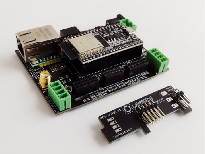
The entire contents of Lavritech V7.1 Lite can be divided into three parts: the core (ESP32 and everything on the motherboard), internal plug-ins and external docking blocks on a DIN rail.
In this article I will talk about programming the controller core and internal plug-ins, and a separate article will be devoted to working with external Wirenboard blocks on a DIN rail.
So, how to program this miracle of technology?
Ready firmware
Since the core of the Lavritech V7.1 Lite controller contains ESP32, you can program it as you like in any of the many programming environments that support it. Or, instead of programming, you can use one of the ready-made publicly available firmware for ESP32.
The developers themselves adhere to the second option, according to their idea, the necessary controller configuration is selected from standard blocks and modules, as in the Lego constructor, then the finished firmware is uploaded - and the controller is ready to work.
This method has many advantages: you don’t need to be a programmer, you don’t need to spend time writing software (as well as debugging it and other procedures), you don’t need to invent anything - you just uploaded the firmware and put the controller into operation. For many people who just need to quickly solve some of their applied automation tasks, this is a good solution.
There are many publicly available firmware for ESP32 and for every taste. In this article, I will not dwell on the description of working with ready-made firmware (there is more than enough information and instructions on them on the Internet). Next, we will talk about a much more interesting topic - self-programming Lavritech V7.1 Lite.
Self-programming
This option is not suitable for everyone, but only for those who have the time and desire to do programming. But on the other hand, by programming the microcontroller yourself, you get complete freedom and can realize all your “Wishlist” and the way you want it.
The second option has always been closer to me and I have always preferred not “fish”, but “fishing rod”, therefore I have never used (and do not plan to use) ready-made firmware.
In addition, by programming the microcontroller yourself, you can not only implement typical functions available in ready-made firmware, but also create your own IoT architecture with the unique functionality of individual controllers.
Explanation.The computing power of the ESP32 is such that (each) microcontroller in the IoT network can contain both hardware control and a developed web interface and top-level multi-layer logic, which makes it superfluous to use (expensive, power-hungry and often "leaky" in specific implementation) mini-computers on Linux (but no ready-made firmware for ESP32 provides such functionality).
In general, for me there is no question “use ready-made firmware or program Lavritech V7.1 Lite myself”, especially since we are talking about ESP32, which provides all the possibilities for this.
Getting Started Programming
As I noted above, ESP32 (Lavritech V7.1 Lite) can be programmed in any of the many programming environments. You can use your favorite IDE for this, but I will program and provide code examples for Arduino (version 1.8.5).
Programming the controllers on the ESP32 can be divided into several parts:
0 - programming the ESP32 itself
1 - programming the connected components
2 - programming the communication functions
3 - programming the application logic of different levels
4 - programming the web interface (if any)
In this article, we will talk about 0- m and 1st aspects, that is, about programming the ESP32 itself and the components connected to it.
In order to create any functional firmware, you first need to learn how to work with its individual parts. Next, I will sequentially analyze the "atomic" programming of individual components of Lavritech V7.1 Lite.
Pinout
Let's start with the pinout. The illustration below should tell you a lot about the Lavritech V7.1 Lite device. If something is not clear, then we will often return to this pinout and use it in our work (I will try to give the necessary explanations).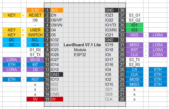
Here we see 2 SPI interfaces for a wireless LoRa module and a network board on the W5500, as well as multifunctional GPIOs (I36, S1_RX, S1_TX, S3_RX, S3_TX, S3_G1, S3_G2) output to various connectors on the motherboard.
Let's start with the analysis of programming the Lavritech V7.1 Lite Ethernet interface.
Ethernet interface on W5500

Using the Ethernet interface on the W5500 is somewhat atypical for ESP32 controllers. Usually, LAN8270A "physics" chips are used in this capacity. It cannot be said that the W5500 is definitely a bad option, the W5500 chip itself has 8 hardware sockets and works great in microcontrollers. Perhaps the LAN8270A is a more correct option, but the W5500, in my opinion, is quite acceptable.
In the case of Lavritech V7.1 Lite, the W5500 is “planted” on non-standard pins of the SPI interface MISO (15), MOSI (2), SCK (0) and CS (4), which is not fatal, but will require some additional gestures from us on their at a construction site.
Note. On the ESP32, SPI2 (HSPI) and SPI3 (VSPI) are available to us for custom programming with default pins, respectively 12.13, 14.15 and 5, 18.19, 23.
As an example, let's create a sketch to get the exact time from an NTP server on the Internet. To work, we need the Ethernet Library for Arduino library .
/*
  Ethernet test (Lavritech V7.1 Lite)
*/

#include <SPI.h>
#include <Ethernet.h>
#include <EthernetUdp.h>

#define ETH_MISO 15
#define ETH_MOSI 2
#define ETH_SCK 0
#define ETH_SS 4

byte mac[] = {0xDE, 0xAD, 0xBE, 0xEF, 0xFE, 0xED};
EthernetUDP Udp;

unsigned int localPort = 8888;
const char timeServer[] = "time.nist.gov";
const int NTP_PACKET_SIZE = 48;
byte packetBuffer[NTP_PACKET_SIZE];

void setup() {
  Serial.begin(115200);
  Serial.println(F("Start..."));

  SPI.begin(ETH_SCK, ETH_MISO, ETH_MOSI, ETH_SS);

  initEth();

  Serial.println(F("loop..."));
} // setup

void initEth() {
  Serial.println(F("initEth..."));
  Ethernet.init(ETH_SS);

  if (Ethernet.begin(mac) == 0) {
    Serial.println(F("Failed to configure Ethernet using DHCP"));
    delay(2000);

    if (Ethernet.hardwareStatus() == EthernetNoHardware) {
      Serial.println(F("Shield not found"));
    }

    if (Ethernet.linkStatus() == LinkOFF) {
      Serial.println("Cable not connected.");
    }
    while(true) {}
  } else {
    Serial.println(F("Start Eth & UDP"));
    Udp.begin(localPort);
  }
} // initEth()

void sendNTPpacket(const char * address) {
  memset(packetBuffer, 0, NTP_PACKET_SIZE);

  packetBuffer[0] = 0b11100011;
  packetBuffer[1] = 0;
  packetBuffer[2] = 6;
  packetBuffer[3] = 0xEC;
  packetBuffer[12]  = 49;
  packetBuffer[13]  = 0x4E;
  packetBuffer[14]  = 49;
  packetBuffer[15]  = 52;

  Udp.beginPacket(address, 123); // NTP requests are to port 123
  Udp.write(packetBuffer, NTP_PACKET_SIZE);
  Udp.endPacket();
}

void parse() {
  if (Udp.parsePacket()) {
    Udp.read(packetBuffer, NTP_PACKET_SIZE);

    unsigned long highWord = word(packetBuffer[40], packetBuffer[41]);
    unsigned long lowWord = word(packetBuffer[42], packetBuffer[43]);
    unsigned long secsSince1900 = highWord << 16 | lowWord;
    const unsigned long seventyYears = 2208988800UL;
    unsigned long epoch = secsSince1900 - seventyYears;

    Serial.print("UTC time is ");
    Serial.print((epoch % 86400L) / 3600); Serial.print(":");
    if (((epoch % 3600) / 60) < 10) {Serial.print('0');}
    Serial.print((epoch  % 3600) / 60); Serial.print(':');
    if ((epoch % 60) < 10) {Serial.print('0');}
    Serial.println(epoch % 60);
  }
}

void checkTime() {
  sendNTPpacket(timeServer);
  delay(2000);

  parse();
  Ethernet.maintain();
}

void loop() {
  checkTime();
  //displayTime();
  delay(5000);
}
Here, requests are periodically sent and responses are received with the exact time from the NTP server. I think it makes no sense to analyze the sketch itself - everything is obvious there. I will only note that our Ethernet module on the W5500 works fine in conjunction with the ESP32 on the Lavritech V7.1 Lite board.
Working with LoRa module

My revision of the Lavritech V7.1 Lite board provides for the installation of popular Chinese LoRa modules (on the back of the board). The board also contains an SMA connector for connecting a LoRa antenna. By itself, the usefulness of having a wireless LoRa connection in the controller is beyond doubt, it remains only to use this module in the firmware code.
In general, this is a simple and familiar task, a slight difficulty in this case lies in the fact that the basic VSPI is already occupied by the Ethernet interface, and the LoRa module is “planted” on non-standard pins 19 (MISO), 27 (MOSI), 5 (CLK).
As a result, we will have to apply some magic and reassign the default pins of the HSPI interface to non-standard pins of the connected LoRa module.
We also need to define and enable the other LoRa service GPIOs of the NSS (21), RST (18) and D0 (12) module.
/*
  LoRa Sender (Lavritech V7.1 Lite)
*/

#include <SPI.h>
#include <LoRa.h>

#define LORA_MISO 19
#define LORA_MOSI 27
#define LORA_CLK   5

#define LORA_NSS  21
#define LORA_RST  18
#define LORA_D0   12

SPIClass hhSPI(HSPI);

long count = 0;

void setup() {
  Serial.begin(115200);
  Serial.println(F("Start LoRa Sender..."));

  hhSPI.begin(LORA_CLK, LORA_MISO, LORA_MOSI, LORA_NSS);
  LoRa.setSPI(hhSPI);
  LoRa.setPins(LORA_NSS, LORA_RST, LORA_D0);

  if (!LoRa.begin(868E6)) {
    Serial.println(F("Starting LoRa failed"));
    while(true);
  }
}

void loop() {
  Serial.print(F("Sending packet: ")); Serial.println(count);

  LoRa.beginPacket();
    LoRa.print(F("Sending packet: ")); LoRa.print(count);
  LoRa.endPacket();

  count++;
  delay(5000);
}
This sketch generates and sends LoRa data packets to the air every 5 seconds. In other words, we were able to successfully enable the operation of two devices (Ethernet and LoRa) on two ESP32 SPI interfaces with connection to non-standard GPIO numbers.
And control of real sendings of LoRa packets to the air using the popular SDRSharp program. Everything works great and exactly as expected.
Buttons on the board
The Lavritech V7.1 Lite board has two buttons that the user can use for their own needs. These are the USER (SAFE) button on the GPIO34 and the SWTH button (switch) on the GPIO35. Programming them is trivial and does not require much explanation.
/*
  Keys test (Lavritech V7.1 Lite)
*/

#define KEY_USER 34
#define KEY_SWTH 35

void setup() {
  Serial.begin(115200);
  Serial.println(F("Keys test starting..."));

  pinMode(KEY_USER, INPUT);
  pinMode(KEY_SWTH, INPUT);
}

void loop() {
  Serial.print(F("USER: ")); Serial.println(digitalRead(KEY_USER));
  Serial.print(F("SWTH: ")); Serial.println(digitalRead(KEY_SWTH));
  Serial.println();
  delay(1000);
}
There is no SWITCH button on my board. The USER button in the initial state gives out "1", when pressed - "0".
Further, from the components soldered on the motherboard, we proceed to the analysis of the programming of plug-in (and, if necessary, disconnected) internal Wirenboard modules.
Wirenboard module WBE2-DI-DR-3

In general, there are a huge number of such modules in the assortment of Wirenboard and other manufacturers, for every taste and for any automation needs. I have several such modules at my disposal, one of which is WBE2-DI-DR-3 (3 “dry contact” inputs), we will begin to analyze their programming from this module.
As you remember from the previous article, the Wirenboard connectors on the Lavritech V7.1 Lite board can be configured as either I2C or UART (GPIO). In my case, one of the two Wirenboard connectors is configured as I2C (WB1.2), and the second as UART (WB1.1).
Since the WBE2-DI-DR-3 module is designed to work with conventional GPIO lines (not I2C), it is obvious that you need to connect it to WB1.1. The diagram of the WBE2-DI-DR-3 module itself would not interfere here, but, unfortunately, Wirenboard does not disclose the diagrams of its modules, so we will limit ourselves to the public pinout of the connector.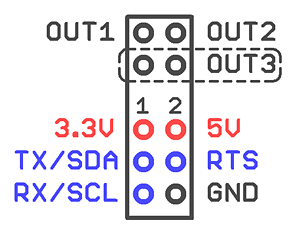
In the context of programming, we are interested in pins TX, RX and RTS highlighted in blue. This is nothing but the GPIO lines we need (input from the ESP32 side). You can ignore the slightly strange names in this case, TX, RX and RTS are just designations for some of the possible roles of these GPIO lines.
To determine which specific GPIO lines the TX, RX and RTS pins in the WB1.1 connector are connected to, go to the manufacturer's website and see the following pinout:
And we set that RX is GPIO25, TX is GPIO26, and RTS is GPIO22. Next, it’s a matter of technology, we create an appropriate sketch and work with input digital signals in any way through the WBE2-DI-DR-3 module.
Note. R19, R20 and R26 marked in green are configuration resistors (jumpers) that connect GPIO25, GPIO26 and GPIO22 to the pins of the WB1.1 connector (seen in the photo above).
/*
  DI test (Wirenboard WBE2-DI-DR-3)
*/

#define DI1 25 // S1_RX
#define DI2 26 // S1_TX
#define DI3 22 // S3_G2

void setup() {
  Serial.begin (115200);
  Serial.println(F("Start DI test..."));

  pinMode(DI1, INPUT);
  pinMode(DI2, INPUT);
  pinMode(DI3, INPUT);
}

void loop() {
  Serial.print(F("DI1: ")); Serial.println(digitalRead(DI1));
  Serial.print(F("DI2: ")); Serial.println(digitalRead(DI2));
  Serial.print(F("DI3: ")); Serial.println(digitalRead(DI3));
  Serial.println();
  delay(2000);
}
In general, if you once understand the logic of organizing the internal connectors of Lavritech V7.1 Lite, then connecting and programming the internal Wirenboard and EUHP modules becomes simple and understandable.
Wirenboard module WBE2-DO-OC-2

Wirenboard module WBE2-DO-OC-2 is 2 open collector outputs. According to the information from the manufacturer's website, switching is carried out by an N-channel field-effect transistor (as part of the assembly), the maximum switching voltage is 40 V DC, the maximum switching current is 1 A (for each channel).
Connecting WBE2-DO-OC-2 to Lavritech V7.1 Lite is also no problem - since we are talking about simple control using GPIO, you need to install this module in the same WB1.1 connector.
Since there is only one such connector on the Lavritech V7.1 Lite board, we can use either the WBE2-DI-DR-3 or WBE2-DO-OC-2 module, but not both at the same time, for this we need to work with the full version of the controller Lavritech V7.1 (without Lite prefix), where more connectors are available.
Or we need to solder the resistors R21-R24 and reconfigure the WB1.2 (I2C / UART) connector accordingly.
Scheme of connecting the load to the outputs of the WBE2-DO-OC-2 module from the Wirenboard website.
Output control sketch. The already familiar GPIO25 and GPIO26 are involved here (GPIO22 is “resting”). The module outputs are connected to the block to contacts Q1.1 (DO2) and Q2.1 (DO1).
/*
  DO test (Wirenboard WBE2-DO-OC-2)
*/

#define DO1 25 // S1_RX
#define DO2 26 // S1_TX

#define PERIOD 5000

void setup() {
  Serial.begin (115200);
  Serial.println(F("Start DO test..."));

  pinMode(DO1, OUTPUT);
  pinMode(DO2, OUTPUT);
}

void loop() {
  Serial.println(F("HIGH"));
  digitalWrite(DO1, HIGH); // Q2
  digitalWrite(DO2, HIGH); // Q1

  delay(PERIOD);
  digitalWrite(DO1, LOW);
  digitalWrite(DO2, LOW);
  delay(PERIOD);
}
This sketch once every 5 seconds (synchronously) turns on and off the open collector outputs of the WBE2-DO-OC-2 module connected to the WB1.1 connector (region/socket S1). Further, with these outputs, you can do whatever you want, in accordance with the logic of the automation task you are solving.
I have two more RS485 interface modules manufactured by Wirenboard (WBE2-I-RS485-ISO) and Lavritech (RS485 V1), but this is a vast topic and I will leave the analysis of their connection and programming for a separate article.
Conclusion
In this article, we have analyzed the programming of the internal modules of the Lavritech V7.1 Lite controller, in the next article I will introduce you to the programming of external plug-in Wirenboard blocks on a DIN rail, the assortment of which is amazing in its diversity (and allows you to solve almost any automation task) .

