How Does the Boutronic JGA2060 Share SDI-12 Sensor Data over W5500 Ethernet?
Boutronic’s JGA2060 lets a PLC and a web client read the same SDI-12 sensor over Ethernet. Firmware v1.0c also reports the age of each measurement.
0
Components
Hardware components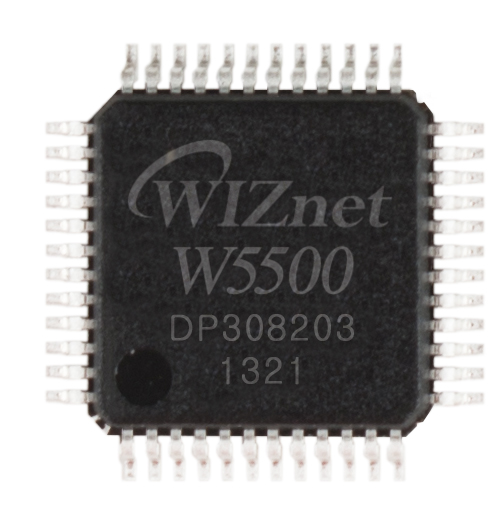
WIZnet - W5500
x 1

Ethernet interface named in JGA2060 diagnostics, manual page 15.
Project description
One field sensor, two ways to read it
The Boutronic JGA2060 polls SDI-12 sensors and makes their readings available over W5500 Ethernet. A programmable logic controller (PLC) can read Modbus TCP registers, while a web application can request JSON over HTTP. This matters when the same soil or environmental probe supplies a control system and a dashboard. Each client gets a familiar interface, and just one device on the sensor bus is responsible for asking the probe for a measurement.
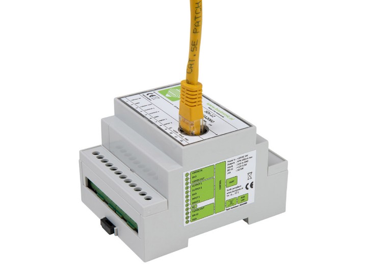
Boutronic B.V., based in ’s-Gravenzande in the Netherlands, designs and manufactures the DIN-rail gateway. The hardware predates the web interface. Boutronic says units shipped from November 1, 2026 carry firmware v1.0c, which adds an HTTP API and a way to tell how old a measurement is. The company accepts price requests under the model number JGA2060. Its enclosure and terminals are visible in the manufacturer’s product photographs.
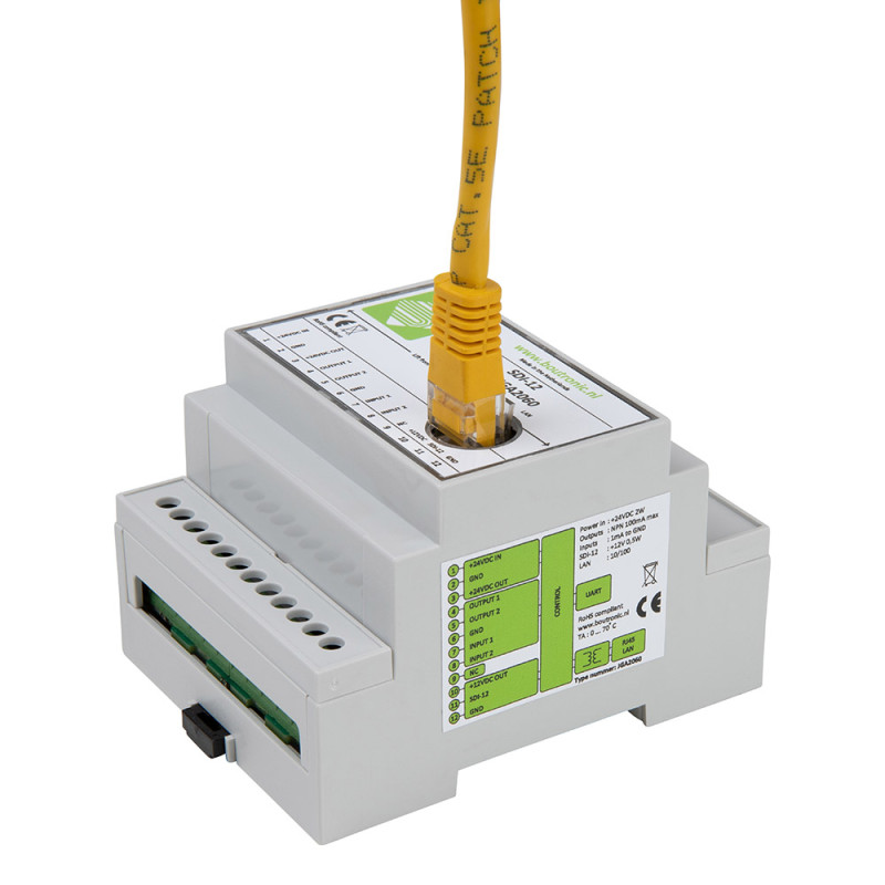
The Ethernet jack and labeled sensor terminals on the JGA2060. Product photograph from Boutronic.
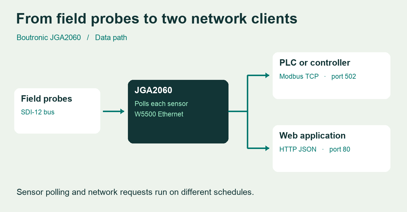
The JGA2060 polls the sensor bus. Network clients read the resulting measurements through two application interfaces.
Where the W5500 sits
SDI-12 is a three-wire serial interface used by environmental instruments. The gateway is powered from 24 V DC and provides a 12 V sensor supply rated at 200 mA in total. The ten supported sensor addresses run from 0 through 9, and each sensor can provide up to 100 values. An installer therefore has two separate checks to make when adding a probe: whether an address is free and whether the combined current fits the supply.
The W5500 handles the wired Ethernet connection on the network side. Boutronic identifies the chip in diagnostic code 8 on page 15 of its model-specific manual. The gateway firmware decides when to query the sensor and how to present the result. A faster Ethernet polling loop can retrieve the same value several times between measurements.
How fresh is the number on screen?
A successful network request tells you that the gateway answered. The age field tells you when the sensor last supplied that value. A client can request /api/v1/sensor/2 for sensor 2. The JSON response identifies the vendor and model, then returns values with an index, a reading and its age in seconds. In the manual’s example, an age of 3 means the gateway received that value three seconds earlier. Its counter returns to zero when a fresh reading arrives.
This helps with a fault that is easy to miss on a dashboard. A steady reading might mean the measured condition is stable, or it might mean the probe stopped supplying fresh data. An application can compare the reported age with the configured measurement interval before presenting that reading as current. The appropriate threshold depends on the sensor and its purpose.
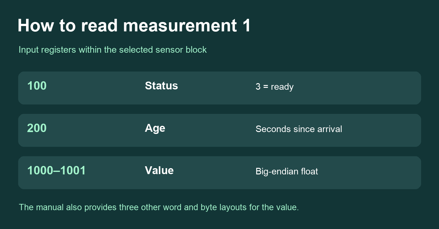
Three separate fields describe measurement 1. The register numbers are the manual’s addresses within the sensor block.
Getting the same result into a PLC
The SDI-12 sensor address is also its Modbus unit ID. For the first measurement in that sensor’s block, Boutronic lists status at input register 100 and age at 200. A status value of 3 means a result is ready. The big-endian representation of that result begins at 1000 and occupies two registers. The gateway also provides three other byte and word orderings. A plausible-looking number can still be wrong if a PLC assembles those two words in a different order.
Boutronic provides a convenient value for sorting that out before connecting process logic. Device uptime appears in four float layouts beginning at 6010, 6012, 6014 and 6016. Comparing the decoded values with the gateway’s reported uptime helps establish the correct layout. For an integrator quoting a monitoring cabinet, a useful first test is to connect one representative probe, compare its value and age in both interfaces, and repeat after unplugging it. Record the required probe current and polling interval alongside the model and firmware version when requesting a quote.
Choosing a polling interval for a real probe
A panel builder evaluating a soil-monitoring cabinet can start with one question for the instrumentation team: how often does the application need a new reading? The JGA2060 accepts per-sensor intervals from zero to 3,600 seconds. Zero tells the gateway to collect values as quickly as the instrument allows. Each probe still needs time to make its measurements and return them over the 1,200-baud serial bus. A dashboard which refreshes once per second and a probe which measures once per minute can coexist, provided the dashboard shows the age alongside the value.
The number of connected probes matters as well. A physical switch selects single-sensor or multiple-sensor operation. In single-sensor mode the gateway stops searching other addresses once it finds the instrument, giving it more opportunities to revisit that probe. In multiple-sensor mode the gateway continues looking through the supported addresses. When expanding a one-probe cabinet, commissioning therefore includes changing this setting as well as allocating the new probe a unique address. A successful read from the original probe alone would miss that configuration issue.
There is another compatibility check for older instruments. The gateway can request and verify a cyclic redundancy check, a short check value used to detect a corrupted message. Boutronic documents this option for SDI-12 version 1.3 and later. Its manual also records cases of probes calculating the check incorrectly and the gateway rejecting their readings. If Ethernet communication works but a particular probe supplies no usable values, the sensor’s reported SDI version and the checksum setting are two concrete things to compare.
Bringing the PLC and dashboard online
A commissioning technician can start at the gateway’s local web page before building either client. The page lists the gateway model, firmware version, serial number and uptime, plus the vendor, model and address of each detected sensor. For an existing cabinet this is a quick way to establish whether the installed unit has the v1.0c web API. The page also shows the addresses of connected Modbus clients, useful when several controllers share a cabinet network.
A dashboard can make the same initial checks through the published API. Reading /api/v1/device supplies the installed software version and device identity. Reading /api/v1/sensor supplies the number of detected instruments and their addresses. The application can then request each identified sensor instead of assuming that the installer used consecutive addresses. If the gateway reports only address 2, there is no reason for that client to query addresses 0 and 1 for measurement data.
Finally, label the channels using the probe’s own documentation. The JGA2060 describes an indexed list of values, and the manual’s example identifies a sensor manufacturer and model. The sample JSON does not attach a measurement unit to each list item. An integrator who sees a decimal number in position 1 still needs the probe’s channel definitions to label it correctly. Record the probe model, channel index, expected units and normal reporting interval together. That makes the same measurement recognizable in the PLC program and on the dashboard.
The same cabinet can also incorporate discrete signals. The JGA2060 includes two digital inputs and two NPN outputs that can be configured for access through Modbus. A project with a small number of local signals can check those electrical ratings while choosing the gateway. The separate output-supply terminal is directly coupled to the incoming supply, whereas the sensor terminals provide 12 V. Distinguishing those terminal groups during panel design matters even when all the data will ultimately appear in one PLC.
A team designing a gateway for a different sensor bus can use the W5500 reference schematic to evaluate its own Ethernet interface. The Boutronic register map is the place to start for a PLC connecting to this finished gateway. W5500 reference schematic and driver
FAQ
Q. Can an existing Modbus client keep reading the gateway? Yes. The manual lists Modbus TCP on port 502. The v1.0c HTTP API is an additional interface on port 80.
Q. Does each sensor value carry its own age? Yes. The JSON response includes an age for each item in the values array, and the Modbus map has separate age registers for the individual measurements.
Q. What if the probes together draw more than 200 mA? The quoted 200 mA is the shared sensor supply rating. Check the probes’ combined current against the manual and discuss the supply arrangement with Boutronic before specifying the cabinet.
Q. What can I check without writing a client? Boutronic Studio 3 displays measurements, provides a terminal for direct sensor communication and can back up settings. The gateway web page lists sensor identity and connection status.
Q. Can two identical probes share one address? Each connected instrument needs a unique address between 0 and 9. Its address also selects the corresponding Modbus unit, regardless of whether the probes are the same model.
For a different field bus with a similar PLC integration problem, see the Wittelb RS485-to-Modbus TCP gateway on WIZnet Maker.
Documents
-
JGA2060 product page and photographs
Manufacturer specifications, firmware shipping date and price request.
-
SDI-12 to LAN converter manual v1.0c
W5500 diagnostics, Modbus map, sensor power budget and HTTP/JSON examples.
-
Boutronic manufacturer profile
Dutch engineering and manufacturing company.
-
Boutronic contact
Product inquiry and manufacturer contact details.


