How Does W5500 Connect Camera-Based Underfloor Heating Flow Readings to a Browser?
Tomas McGuinness uses an ESP32-S3 camera to read heating flow indicators and a W5500 Ethernet link to serve calibrated readings and local history.
0
Components
Hardware components
WIZnet - W5500
x 1

On the Waveshare ESP32-S3-ETH board; SPI Ethernet through ESP-IDF.
Project description
Reading a heating manifold without opening the pipes
UFH Manifold Monitor turns three mechanical underfloor-heating flow indicators into browser-readable measurements. Tomas McGuinness, a developer based in Solihull, uses an ESP32-S3 camera board to locate the indicators' red floats, calculate litres per minute, and deliver the results over W5500 Ethernet. The code reviewed here includes the November 6, 2026 update that added flow history and improved float detection.
A heating manifold distributes warm water into separate floor loops. Its transparent indicators show how much water each loop receives, but reading them normally means looking inside the manifold cupboard. McGuinness has documented a three-loop installation in his own heating renovation, giving this project a specific household problem: recording the existing indicators without adding sensors to the water circuit.
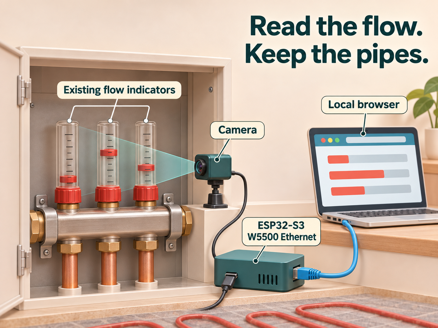
AI-generated installation concept: the camera reads existing indicators without adding sensors to the pipes.
The hardware combines a Waveshare ESP32-S3-ETH board, an OV5640 camera, USB-C power, and an Ethernet cable. The board provides 16 MB of flash and 8 MB of PSRAM, extra memory used for camera-related work and recent flow history. The camera connects through the board's digital video port rather than sending its pictures over a separate network.
How does a red float become a number?
The ESP32-S3 captures a 2560 × 1920 JPEG once every 60 seconds. The current algorithm concentrates on the horizontal image band containing the indicators, accumulating rows 80 through 419 instead of processing the whole frame into a full-size colour buffer. Within that band, each tube has a predefined horizontal search strip.
The firmware first finds the red cap below each indicator, then looks for the float ring above it. This relative measurement matters because a camera can move slightly after installation. During development, a roughly 15-pixel camera shift made a fixed search window confuse a cap edge with the float; the November 6 revision anchors the ring search to the cap position.
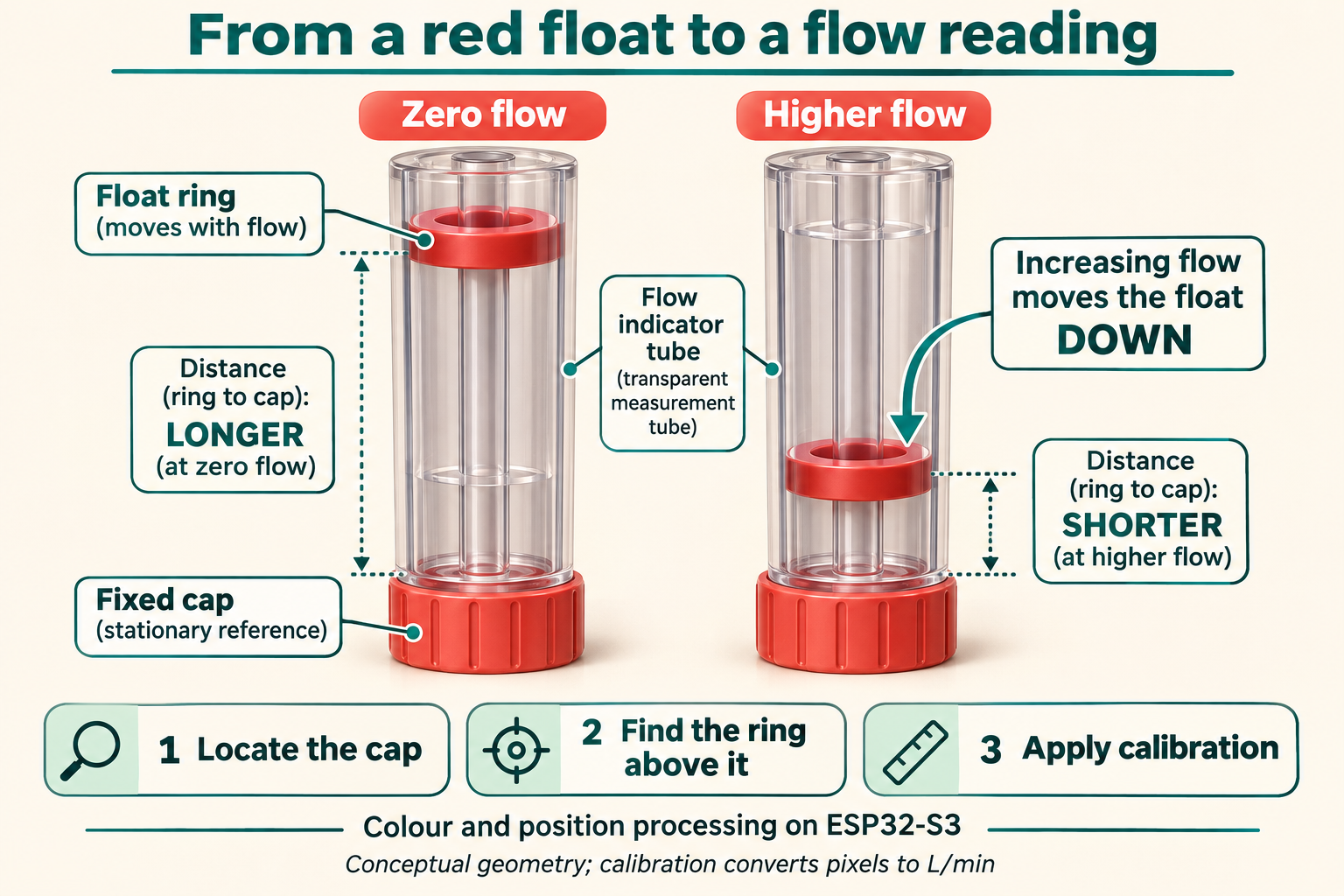
Generated optical explainer: higher flow lowers the ring toward the fixed cap. Calibration converts the observed position into L/min.
Each loop has a stored zero position and a pixels-per-litre-per-minute scale. Calibration uses a zero-flow reference followed by a known reading taken from the physical indicator; the repository's default values come from the author's November 6 reference frames. This is colour and position processing on the microcontroller, with no trained recognition model or cloud image service in the measurement path.
The cap-relative search tolerates small shifts, but the tube strips and decoded row band remain fixed in code. A larger movement requires adjusting those regions. Consistent lighting is also part of the installation: in a dark cupboard, image noise can weaken the detected ring until the firmware reports no reading, so a fixed camera position and soft, even illumination are useful before calibration.
What does the local dashboard provide?
The dashboard shows a drawing of the three indicators, the current flow for each loop, total flow, and the balance between loops. A camera tab exposes the captured view for alignment, while loop names can be changed and retained in nonvolatile storage. The JSON endpoint /api/flows also supplies values, measurement state, and the age of the last reading for another local application to consume.
The November 6 history implementation stores one sample per minute in a seven-day ring buffer. A request for between one and 168 hours returns at most 720 averaged points, keeping the browser response manageable. History lives in PSRAM and disappears after a restart, so this feature provides a recent local view rather than a permanent heating record.
The interface includes a clearly labelled sample-value preview for checking the drawing before measurements are available. Those preview numbers are synthetic; actual readings come from the camera and calibration path. MQTT and Matter publication remain future options in the project plan, while HTTP, the camera image, and local history are implemented in the reviewed code.
Where does W5500 fit in the system?
The ESP32-S3 runs both the optical algorithm and the web application. Its Ethernet initialization selects the W5500 driver through ESP-IDF and connects the controller over SPI at 25 MHz. The W5500 supplies the board's wired Ethernet interface, carrying browser requests, flow JSON, camera frames, and firmware uploads between the device and the local network.
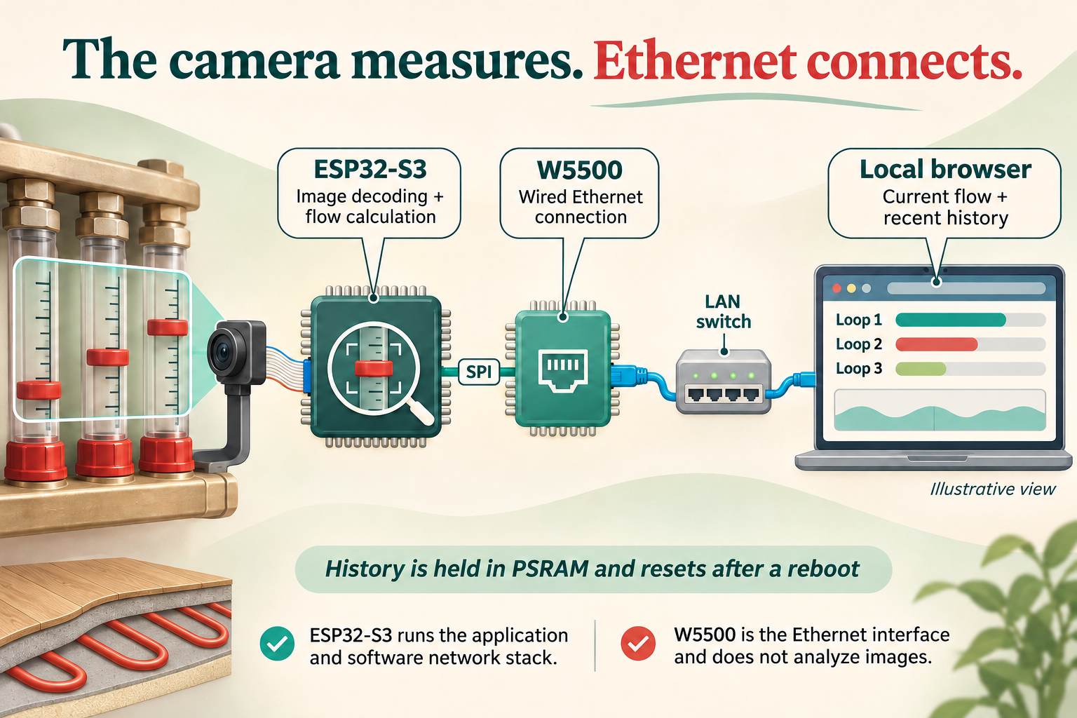
Generated system illustration: ESP32-S3 runs the measurement and application logic; W5500 carries Ethernet traffic to the local browser.
Although W5500 includes hardware TCP/IP capabilities, this implementation uses ESP-IDF's Ethernet-driver and network-stack path. The useful distinction is the division of work: camera interpretation belongs to the ESP32-S3, while W5500 provides the Ethernet connection. A cable gives a fixed installation a direct LAN route, and the current firmware does not use an additional Wi-Fi path.
The firmware tab supports network updates after an initial USB flash. Updates use a spare firmware slot, and a new image is retained after the device obtains an IP address and starts its web server. The upload endpoint currently has no authentication, so this prototype belongs on a trusted local network rather than an internet-exposed address.
A useful prototype with a clear next step
UFH Manifold Monitor demonstrates an approachable way to add digital observation to an existing mechanical display. Its most reusable ideas are the cap-relative reference, per-loop calibration, and a browser interface that keeps the latest value's age visible. Longer-term storage or home-automation integration can build on the JSON interface as the project develops.
The available reference frames and implementation describe a developer prototype, with no published accuracy study or independent long-duration installation report. Readers starting with the network layer can follow the same author's earlier work in Setting Up W5500 Ethernet on ESP32-S3 Using ESP-IDF; this newer project adds an optical measurement application to that foundation.
Frequently asked questions
Q. Does the project need an electronic flow sensor? No. A camera reads the red floats in the existing mechanical indicators, and the ESP32-S3 converts their positions into calibrated values.
Q. Does W5500 process the camera image? No. The ESP32-S3 performs image decoding and float detection; W5500 provides the wired Ethernet connection.
Q. Is this an AI vision project? The reviewed code uses colour and position rules with calibration, rather than a trained machine-learning model.
Q. Does flow history survive a reboot? No. The seven-day history buffer is held in PSRAM, while calibration and loop names use persistent storage.
Q. Can it already publish to Matter or MQTT? Those integrations are planned. The current implementation exposes measurements and history through a local web interface and HTTP JSON.
Documents
-
UFH Manifold Monitor source
Original firmware, build notes, calibration and update instructions.
-
Reviewed November 6 revision
Pinned code with cap-relative detection and local history.
-
W5500 Ethernet implementation
Exact W5500 driver and 25 MHz SPI configuration.
-
Optical flow reader
Colour detection, image band, cap reference and fixed tube regions.
-
Author reference photographs
Real calibration frames; linked without redistributing unlicensed photographs.
-
The author's heating installation
Background on the home installation and three-loop underfloor heating.
-
ESP-IDF Ethernet programming guide
Official Ethernet-driver and network-stack architecture.


