Modbus TCP on the WIZnet ESP SoM, re-addressable from a browser
Modbus TCP slave plus a live web dashboard on a WIZnet ESP SoM. Change the IP from the browser. Same firmware on W5500 or W6300, one menuconfig switch.
1
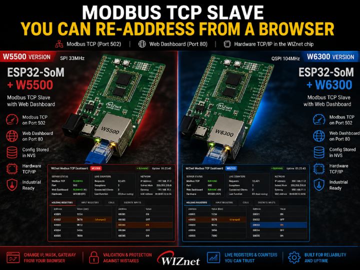
Components
Hardware components
WIZnet - W5500
x 1

WIZnet - W6300
x 1
Project description
What You Will Build
[Modbus TCP GitHub Link]
A Modbus TCP slave that any master can poll on port 502 — and that you can re-address from a browser when the subnet on site turns out not to be the one on the drawing.
By the end of this post the device is answering a Modbus master, showing its own registers live on a web page, and taking a new IP address without a laptop, a USB adapter, or a vendor tool.
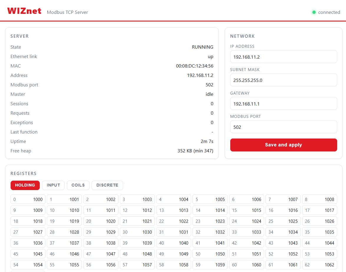
Server state, live counters, and the network settings — all served from the device itself.
What is running when you are done:
- Modbus TCP slave on port 502 — holding registers, input registers, coils, discrete inputs
- Web dashboard on port 80 — live register values and request counters
- Network settings in NVS — IP, mask, gateway, and the Modbus port itself
- Both servers on the WIZnet chip's hardware TCP/IP. The MCU runs no TCP stack.
What You Need
| Item | Note |
|---|---|
| WIZnet ESP32-SoM | ESP32-S3 plus a WIZnet Ethernet chip on one module. W5500 or W6300 — the firmware takes either. |
| Evaluation board for the SoM | Supplies USB, the RJ45, and the reset/boot buttons. |
| Ethernet cable | To a switch or straight to the PC. |
| USB cable | Flashing and the serial console. |
| ESP-IDF v6.0 or later | Earlier versions will not build this example. |
| A Modbus master | Optional. The example ships its own probe, so you can finish without one. |
[ IMAGE: shared/som_w6300.jpg ]
The W6300 SoM on its eval board. Same module footprint as the W5500 version.
Hardware Setup
Three connections, and none of them are unusual.
- Seat the SoM on the evaluation board.
- Ethernet from the RJ45 to your switch, or straight to the PC.
- USB from the board to the PC.
Put the PC on the same subnet as the device's default address. The example ships with 192.168.11.2, so give the PC something like 192.168.11.10 with mask 255.255.255.0. If you skip this, everything below builds and flashes correctly and nothing answers.
Get the Example
The driver is on the ESP Component Registry, so there is nothing to clone. Create a project and pull it in.
idf.py create-project my_project
cd my_project
idf.py add-dependency "wiznet/wsm_driver==1.1.0"
idf.py set-target esp32s3
add-dependency writes main/idf_component.yml for you. set-target regenerates sdkconfig, so it has to run before menuconfig.
The component lands here — and it brings every example with it:
managed_components/wiznet__wsm_driver/examples/modbus_tcp/Build that directory directly, or copy it out and make it your own project. Either works.
Success check:
main/idf_component.ymlexists andmanaged_components/wiznet__wsm_driver/appeared. The component is in.
Cloning the repository from GitHub is the other route, and it is the right one only when you want to modify the driver itself or track the development branch.
Configure
1. menuconfig — three items
idf.py menuconfigMain -> Component config -> WIZnet WSM Driver| Item | Default | What it decides |
|---|---|---|
| WIZnet chip | W5500 | Match your board. SPI pins and clock follow the chip automatically. |
| Network backend | TOE (hardware TCP/IP) | Whether the chip owns the TCP/IP stack, or the ESP32-S3's LwIP does. |
| W6300 QSPI mode | Quad | W6300 only. Set to Single if IO2/IO3 are not wired. |
Leave the backend on TOE — that is the whole point of this example, and it is what every number below was measured with.
Per-socket RX and TX buffers are also here (2 KB each by default, 1–16 KB). Leave them alone for a first run.
The SPI host, clock and GPIOs are not in menuconfig at all. They are derived from the chip you picked. Custom wiring means editing the component's Kconfig defaults.
Changing the backend later needs
idf.py fullcleanbefore you rebuild. Skipping it produces a build that links the wrong stack.
2. Addresses and ports
Open inc/net_config.h. The defaults are these:
#define NET_MAC_ADDR    {0x00, 0x08, 0xDC, 0x12, 0x34, 0x56}
#define NET_IP_ADDR     {192, 168, 11, 2}
#define NET_SUBNET_MASK {255, 255, 255, 0}
#define NET_GATEWAY     {192, 168, 11, 1}

#define WIFI_SSID       ""      /* empty -> Ethernet only */
#define WIFI_PASS       ""

#define MB_PORT         502     /* Ethernet */
#define WIFI_MB_PORT    5020    /* Wi-Fi    */
Leave them alone for a first run. The whole point of the web page is that you can change the address later without rebuilding.
Filling in WIFI_SSID brings up a second Modbus server on Wi-Fi at port 5020. Leave it empty for now — one interface is enough to get to a working device.
Build & Flash
idf.py buildThen flash and open the console. Replace the port with yours.
idf.py -p COM6 flash monitor              # Windows
idf.py -p /dev/ttyUSB0 flash monitor      # Linux / macOS
Run
On reset the console should say four things: the chip was found, the network came up, the pins were bound, and the server is listening.
I (360) wsm_driver_spi: W5500 version check OK: 0x04
I (362) wiztoe_net: TOE up: 192.168.11.2 (WIZnet hardware TCP/IP)
I (365) io_bind: coil[0] -> GPIO1, GPIO4 -> discrete[0] (input open)
I (447) mb_server: [eth] waiting for link...
I (451) mb_server: [eth] Modbus TCP server on port 502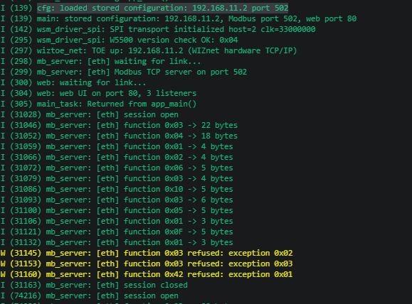
Boot log. The version check is the line that tells you the SPI wiring is right.
If the version check fails, stop here — nothing above the SPI bus can work. If it passes but the link never comes up, the cable or the switch is the problem, not the firmware.
Now open a browser at http://192.168.11.2. The dashboard is served by the device.
Test
The example ships a probe with no dependencies beyond Python itself, so you can verify the server before installing any Modbus tool.
python tools/mb_probe.py 192.168.11.2It exercises every implemented function code, writes values and reads them back, and then asks for three things the server must refuse.
If you already have a master, use it instead — the dashboard updates while it runs, which makes it easy to see whether your master is doing what you think it is doing.
mbpoll -m tcp -a 1 -r 1 -c 10 192.168.11.2       # read ten holding registers
mbpoll -m tcp -a 1 -r 6 192.168.11.2 48879       # write 0xBEEF to holding[5]
mbpoll -m tcp -a 1 -r 6 -c 1 192.168.11.2        # read it back
mbpoll -r 1 addresses the first register. The tools number from 1 and the wire carries a zero-based address, which is the single most common source of "wrong value" reports.
Expected Result
A healthy server prints this and exits 0:
--- reads (the startup pattern from mb_datastore_init)
0x03 holding[30:40]    -> [1030, 1031, 1032, ... 1039]  OK
0x04 input[0:8]        -> [0, 1, 4, 9, 16, 25, 36, 49]  OK
0x01 coils[32:48]      -> [1, 0, 1, 0, 1, 0, 1, 0, ...]  OK
0x02 discrete[16:32]   -> [1, 0, 0, 0, 1, 0, 0, 0, ...]  OK

--- writes, each read back
0x06 holding[5]        -> [48879]  OK
0x10 holding[20:22]    -> [4369, 8738]  OK
0x05 coil[1]           -> [1]  OK
0x0F coils[8:12]       -> [0, 1, 0, 1]  OK

--- refusals (the server must answer, not drop the connection)
0x03 addr 9000         -> b'\x83\x02'  OK
0x03 count 0           -> b'\x83\x03'  OK
0x42 undefined         -> b'\xc2\x01'  OK

15 requests on one connection, 0 failures
Three things to read out of that:
- The startup pattern. Input registers are squares — 0, 1, 4, 9, 16 — so a byte-order mistake or an off-by-one address is visible without a debugger.
- 48879 is 0xBEEF, read back from where the probe wrote it. Writes are verified, not assumed.
- The three
b'\x83...'lines are successes. They are exception replies: the function code with the high bit set, then the exception code. A server that drops the connection instead would fail here.
The console names each function code and the size of the reply, all on one connection:
I (486591) mb_tx: master connected from 192.168.11.4
I (486608) mb_server: [eth] function 0x03 -> 22 bytes
I (486614) mb_server: [eth] function 0x04 -> 18 bytes
...
W (486682) mb_server: [eth] function 0x03 refused: exception 0x02
I (486696) mb_server: [eth] session closed
And the browser shows the same traffic from the device's side:
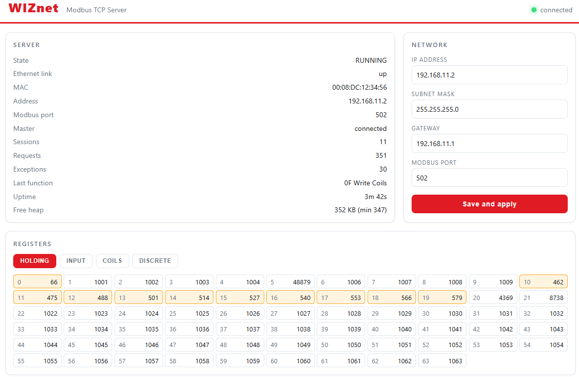
Holding registers updating live. Changed cells flash orange, the Requests counter climbs.
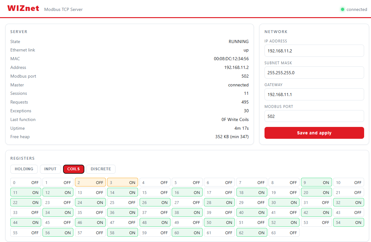
Same view, coils. One bit walking across on every pass.
Try It Yourself
Now the part that is hard to do with a sticker on the case.
Move the device to another address
- Open the dashboard and go to the Network panel.
- Change the IP — say to
192.168.11.50. - Press Save and apply.
- Read the confirmation, then follow the device to its new address.
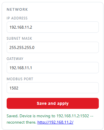
Applied. The device tells you where to find it next.
The console shows the same event from the other side, which is worth watching once so you know the order things happen in.
Then try to break it
Set the Modbus port to 80 and save.
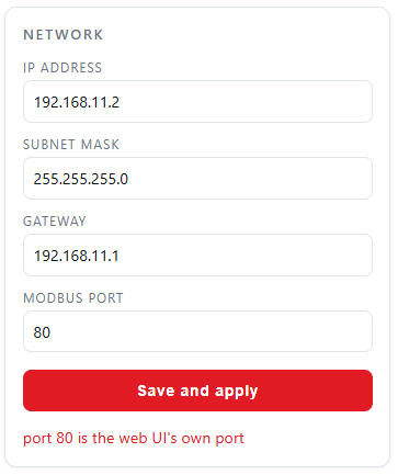
Refused, with the reason: port 80 is the web UI's own port.
Try 255.255.0.255 as a netmask, or a gateway outside the subnet. Each one comes back with a sentence rather than a red border.
How It Works
Changing the IP without bricking the device
You are changing the address of the device you are talking to, through the device you are talking to. Do it in the wrong order and you cut your own connection halfway and leave the box unreachable.
So the apply is deferred:
- Validate everything before touching anything
- Write to NVS
- Answer the browser — so the confirmation arrives on the old address
- Then stop the web server, stop Modbus, and re-address the chip
Saying no properly
Bad input is refused with a reason. The validator checks the three things that actually go wrong on site:
- The netmask must be contiguous —
255.255.0.255is not a netmask - The gateway must be inside the subnet, or there is no route
- The Modbus port cannot collide with the web UI, or you lose the way back in
Two elements are wired to pins
Most of the data model is a pattern in RAM. Two elements are not: coil 0 drives an output pin, and an input pin is published as discrete input 0. A coil written from a master closes a relay on the bench; a contact closed on the bench appears in the master's grid.
The binding is two elements on purpose. It widens by changing an index range.
Anything that can reach this device can close that relay. Modbus TCP on port 502 has no authentication, and neither does the web UI on port 80. With a pin bound, an unauthenticated write is no longer a number changing in RAM — it is a contact closing. Keep this on a bench or an isolated segment.
Architecture
The MCU runs no TCP
Both servers — Modbus on 502 and the web UI on 80 — sit on the WIZnet chip's hardware TCP/IP. The ESP32-S3 hands over payloads and gets payloads back. For an industrial box that is the shape you want: one module to place, one module to qualify, and the stack already on the Ethernet side of it.
Bring-up is one function call
This is the part that surprises people who expect a hardware stack to mean a proprietary API. It does not.
#include "net_backend.h"      /* wiznet_net_init(), wiznet_net_is_up() */
#include "lwip/sockets.h"     /* standard BSD sockets — include AFTER net_backend.h */

wiznet_net_init(&g_net_info);
while (!wiznet_net_is_up()) { }

int s = socket(AF_INET, SOCK_STREAM, IPPROTO_TCP);
bind(s, ...); listen(s, 1); accept(s, ...);
SPI init, chip reset and the network configuration all happen in that one call. After it, socket(), bind(), send() and recv() are the ordinary ones — the driver intercepts the lwIP socket entry points at link time and routes them to the chip's hardware sockets.
wiznet_net_init() has the same name and signature on both backends, so the same application code builds against the hardware stack or the software one. Only one menuconfig line changes.
Two things to get right:
- Include
net_backend.hbeforelwip/sockets.h. The other order fails to build on aSOCK_STREAMname clash. - Add the dependency in
main/CMakeLists.txt:idf_component_register(SRCS "main.c" INCLUDE_DIRS "." REQUIRES wsm_driver)
The TOE limits still apply and are worth knowing before you design around it: eight hardware sockets, IPv4 TCP and UDP only. That is why this example counts its listeners so carefully.
Pick the chip late
The SoM comes as W5500 or W6300, and the firmware does not care which is fitted. One menuconfig option, no code change.
- W5500 — standard SPI.
- W6300 — QSPI. Single mode is the same four wires; quad mode adds IO2/IO3 and moves data on four lines instead of one.
Modbus registers are small, so a 502 slave will never notice the difference. But the same board and the same firmware can carry a heavier job later just by fitting the other chip.
Everything measured below ran on the W5500 version.
Verification scope
The server was run on the ESP32-SoM with both the W5500 and the W6300, over Ethernet and over Wi-Fi, including both interfaces serving at the same time. Every implemented function code and every exception path was exercised against the running device.
The output side of the pin binding was then run for real on an ESP32-S3 board: the coil clears at boot instead of inheriting the demo pattern, a master's write drives the pin and reads back, and the link survives the toggle. The input side is still unverified — no contact has been closed on it, and the debounce has not been measured. No relay board was involved either; the output was checked by what the pin did, not by what a relay did.
Measurements
The bug that was invisible for a week
The netmask check looked like this:
if ((~mask & (~mask + 1)) != (~mask + 1)) {
    /* not contiguous */
}
Looks like a bit trick. Reads like a bit trick. It is never true.
And since it was the first check in the chain, the gateway and port checks below it never ran either. Three validators, all dead, all looking perfectly reasonable in review.
uint32_t host = ~mask;
if (mask == 0 || (host & (host + 1)) != 0) {
    /* not contiguous */
}
What caught it was making the test tool print the reason for a refusal rather than the status code. The moment a valid 255.255.255.0 came back with a mask complaint, it was obvious.
A test that only checks the status code cannot tell "rejected correctly" from "rejected for the wrong reason".
39 out of 300
First load test on the web UI: 300 requests, 39 answered. Three separate causes, none visible by reading the code.
- 200 ms accept timeout across 3 listeners. A request arriving just after listener 1 was checked waited for the other two to time out — 430 ms before the server looked at it.
- Reading the request one byte at a time. Each byte is an SPI round trip. A 300-byte header is 300 round trips.
- A listener left at -1 after a failed accept, silently cutting capacity by a third for the rest of the run.
After: 397 out of 400. Not one of the three was a logic error. All three were "correct code, wrong constant".
The one that needed a badly behaved client
A tool that connects and disconnects wrongly on purpose — half-open connections, disappearing mid-request, connecting and never speaking — scored Modbus at 4 out of 7.
A client that connects and then vanishes leaves the hardware socket in CLOSE_WAIT. The accept path handled ESTABLISHED and CLOSED, but not that, so the listener sat in a state it had no branch for. One dead client, one dead listener, permanently.
The example closes and re-opens a listener that has been idle for N passes. After that, 16 out of 16.
30-minute soak
| Metric | Result |
|---|---|
| Web requests | 5521 / 5522 |
| Modbus transactions | 2761 / 2761 |
| Free heap | flat at 351 KB |
| Heap low-water | never moved |
The flat heap is the number that matters. Both servers allocate per connection, so a leak of even 100 bytes per request would show as a slow slide over 5500 of them.
Troubleshooting
| Symptom | Where to look |
|---|---|
| Version check fails at boot | SPI wiring or the chip selection in menuconfig. Nothing above the bus can work until this line passes. |
| Version check passes, nothing answers | Link and subnet. Is the PC on 192.168.11.x? |
| Master reports "illegal data address" | The 1-based / 0-based difference. mbpoll -r 1 is register 0 on the wire. |
| Values are not the startup pattern | Coil 0 and discrete input 0 are bound to pins and hold whatever the hardware is doing. |
| Writing coil 0 drops the Ethernet link | A relay coil powered from the same 3V3 rail as the Ethernet chip. Use an opto-isolated module with its own supply. |
Next Steps
- Widen the pin binding. The index range is the only thing holding it to two elements.
- Bring up the second interface. Fill in
WIFI_SSIDand a Wi-Fi Modbus server appears on port 5020. Note that each interface owns its own data model — they are two independent slaves, not a redundant pair. - Read the example's tools.
web_probe.pyprints why a request was refused,abuse.pyis the badly-behaved-client suite, andsoak.pyis the long run that watches heap.
The code is examples/modbus_tcp, which arrives with the component at managed_components/wiznet__wsm_driver/ and is also on GitHub. The register map, the full pin table, and the known limits are in that example's README.
Three things worth taking away
- Print the reason, not the code. It found a bug three validators deep.
- Test with bad clients, not just good ones. The good ones scored 100% while a listener was permanently wedged.
- Watch the heap, not the throughput. Throughput says it works now. Flat heap says it will still work tomorrow.
Was this what you needed?
Tell us how this would be used on your site, or what is missing. A repository issue or a comment below both work. What you tell us about your deployment is what sets the next priority.
- Repository: https://github.com/theoim/wsm_driver/tree/ionic-example/examples/modbus_tcp
- Board product pages: (link)
wsm_driver: https://github.com/Wiznet/wsm_driver

