Software Implementation of a Secure Firmware Update Solution in an IOT Context
Software Implementation of a Secure Firmware Update Solution in an IOT Context
0
Components
Hardware components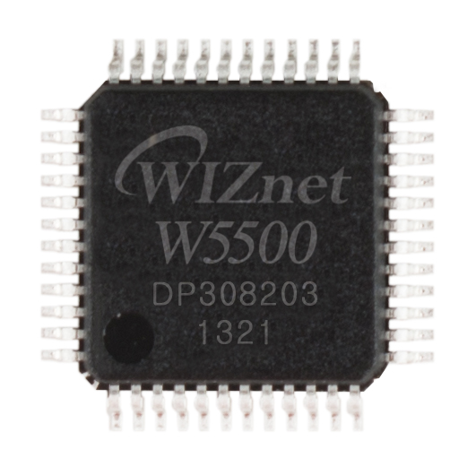
WIZnet - W5500
x 1

PIC32MX340F512H microprocessor
x 1
Project description
The Internet of Things (IoT) has become an important phenomenon due to the rapid pace of technological development. There is a constant stream of new
smart devices to the market, including smartphones,
smartwatches, smart refrigerators and many more. If
this pace continues, IoT technology is soon adopted
by many other industries including mobility, home automation, connected life and energy.
The main idea behind this trend is to connect things
(sensors, actuators, lights, refrigerators, etc.) to existing network infrastructure [1] and [2]. The producers
of IoT devices capitalise on the enthusiastic acceptance
of this new technology by consumers and accelerate
the production processes to shorten the time to market. The rapid pace of development has implications
for the final quality of the devices which often break
down due to Firmware (FW) or Software (SW) defects
[3]. In a continuous development environment, FW
has to be frequently updated for several reasons. The
first one is the need to fix FW and SW bugs after the
product has been released to market. Another reason
is the addition of a new feature to a product that is
already being used. A third reason, which is probably the most important, is the need to protect the devices against cyber-attacks. It can be for instance an
attempt to manipulate an automated driving system
which is a modification of the time parameter when
the car starts to brake. If a default value 0.01 s is
changed by an attacker to 1.1 s, a major collision can
occur. Another example is a sophisticated sensor modification attack involving a change to the FW which
affects the sensing parameters. These attacks are very
dangerous because they can be undetected if no deeper
analysis is done. Therefore, more attention has to be
paid to these threats.
Safety Measures
These methods operate at the protocol level and are
aimed at preventing other types of attacks not eliminated by security measures. For example, these measures can protect the IoT environment against the
aforementioned attacks which target the FW update
process and which can cause the FW image file to
become corrupted, truncated or incomplete. If a corrupted FW image file is loaded onto a device, the device
can have a failure. There may also be damages to assets or even fatalities. To detect attacks, methods such
as the following can be used:
? error detection and correction Cyclic Redundancy
Check (CRC),
? block ciphers,
? packet acknowledgement.
These methods, however, cannot eliminate the
threats, so they have to be combined with memory
partitioning:
? single Banked Partitioning (SBP),
? dual Banked Partitioning (DBP).
The idea of SBP and DBP is that during the update
process, a copy of a working FW version is stored in
the Microcontroller Unit (MCU). If only a portion of
the packets is transferred (e.g. due to an intentional
abortion of the FW update process), the current FW is
not overwritten with the corrupt FW image file. This
means that two FW image files (the original and the
updated version) have to be stored in the MCU at the
same time. This requires additional processor memory,
which results in higher cost.
2) Security Measures
In order to secure the FW update process, data confidentiality, authenticity and integrity must be ensured
in addition to transmission security.
Integrity ? the image file generated by the manufacturer has not been tampered with before this image file
is received by the device. To detect attacks, methods
such as the following can be used:
? Hash function ? a fingerprint of an FW image file is
obtained using a hash function. The fingerprint is
attached to the data transmitted. Once the bootloader received all the data, it computes its own
fingerprint and compares it with the one received.
If the two are equal, the FW is not modified. A
downside of using simple FW hashes is that an attacker can modify the file and subsequently compute a fingerprint. In this case, the bootloader is
not able to detect that the FW has been manipulated.
? Digital signature ? a FW fingerprint is computed
first, then encrypted using a private key (asymmetric encryption). The signature thus obtained
is attached to the FW image file and sent to the
device. The bootloader decrypts the digital signature using a public key and performs a comparison
as when using a hash function.
? Message Authentication Codes (MACs) ? these
are similar to digital signatures except a private
key is used to encrypt and decrypt the fingerprint
(symmetric encryption). A disadvantage of MACs
as compared to digital signatures is that as anyone
can verify a MAC, anyone can create one.
Authentication ? refers to the verification of the
origin of a message. It checks that both the FW image file and the target device originate from the manufacturer. The MAC and digital signature methods
do permit this because by successfully deciphering the
fingerprint, they confirm that the source is authorised.
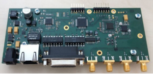
The reader is equipped with 4 antenna ports (SMA
connectors); each port can deliver a maximum output
of 29 dBm, Fig. 4. The reader can be powered through
a DC connector (5 V) or via PoE (48 V). The reader
has an Ethernet module and RS232 interface which is
integrated into a GPIO connector. The reader supports low-level reader protocol (LLRP) and a custom
protocol via UDP and the RS232 interface.
The core of the reader consists of a
PIC32MX340F512H microprocessor, which controls the RFID chip, a W5500 chip for Ethernet
connectivity, which is considered to be unattackable
[13] and other peripherals. The MCU operates at
80 MHz, has a 512 kB flash memory and a 32 kB
RAM; there is no external memory
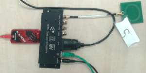
 A test bench is designed to validate the functionality of the bootloader and the bootloader with a FW
image file encryption capability based on an existing
AutoEPCIS UHF RFID reader v.2. It consists of an
update terminal, the IoT device to be updated and
a router (Mikrotik RB2011UiAS-2HnD-IN). A desktop PC is used as the update terminal: it encrypts
the FW image file and sends it to the device through
the router. A USB-UART adapter for debugging, an
Ethernet cable for data communication and a PICkit
3 programmer for the initial upload of the bootloader
to the MCU are also needed. These components are
shown in detail in Fig. 6
 [caption id="attachment_26241" align="alignnone" width="300"]
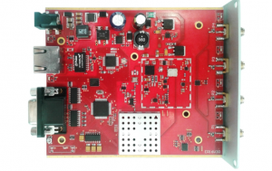 Version 3[/caption]
A test bench is designed to validate the functionality of the bootloader and the bootloader with a FW
image file encryption capability based on an existing
AutoEPCIS UHF RFID reader v.2. It consists of an
update terminal, the IoT device to be updated and
a router (Mikrotik RB2011UiAS-2HnD-IN). A desktop PC is used as the update terminal: it encrypts
the FW image file and sends it to the device through
the router. A USB-UART adapter for debugging, an
Ethernet cable for data communication and a PICkit
3 programmer for the initial upload of the bootloader
to the MCU are also needed. These components are
shown in detail in Fig. 6
[caption id="attachment_26241" align="alignnone" width="300"] Version 3[/caption]

