NASA Lunabotics: Dual-Core RTOS Motor Control & Telemetry System
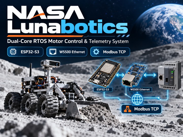
An ESP32-S3 robotics control system using WIZnet W5500 Ethernet and Modbus TCP to communicate with a Beckhoff PLC for motor control and telemetry.
0
Components
Hardware components
WIZnet - W5500
x 1

Espressif - ESP32
x 1
Project description
NASA Lunabotics: Dual-Core RTOS Motor Control & Telemetry System with ESP32-S3 and W5500 Ethernet
University at Buffalo의 NASA Lunabotics rover firmware는 ESP32-S3와 Beckhoff CX7000 PLC를 WIZnet W5500 기반 Wired Ethernet과 Modbus TCP로 연결해 Motor Control과 Telemetry를 처리하는 Robotics 프로젝트입니다.
ESP32-S3의 Dual-Core FreeRTOS 구조를 활용해 Core 0에서는 PLC Communication과 Motor Control을, Core 1에서는 VL53L0X Distance Sensor와 SSD1306 OLED를 처리합니다. W5500은 ESP32-S3와 PLC 사이에서 Motor Command와 Status Data를 전달하는 핵심 Wired Network Interface로 사용됩니다.
전체 구조는 다음과 같이 이해할 수 있습니다.
Control Logic
→ ESP32-S3
→ W5500 Ethernet
→ Modbus TCP
→ Beckhoff CX7000 PLC
→ Motor System
동시에 ESP32-S3는 별도의 Task에서 Distance Sensor와 OLED Display를 처리합니다.
Project Overview
이 프로젝트의 주요 구성은 다음과 같습니다.
- ESP32-S3 Main Controller
- WIZnet W5500 Ethernet Controller
- Beckhoff CX7000 PLC
- Modbus TCP Communication
- VL53L0X Time-of-Flight Sensor
- SSD1306 128×64 OLED
- Dual-Core FreeRTOS
- UART Command-Line Interface
이 구조의 핵심은 Network Communication과 Motor Control을 Sensor 및 Display 처리와 분리해 동작시키는 것입니다.
Dual-Core FreeRTOS Architecture
ESP32-S3의 두 Core는 서로 다른 역할을 담당합니다.
Core 0 — Control & Communication
Core 0에서는 modbus_task가 동작합니다.
이 Task는 Beckhoff PLC와 Modbus TCP Communication을 담당하며 다음 세 가지 작업을 반복합니다.
- Motor Control Word Write
- Target Speed Word Write
- Motor Status Word Read
Modbus Register는 다음과 같이 정의되어 있습니다.
| Data | Register | Role |
|---|---|---|
| Control Word | 0 | Motor control state |
| Speed Word | 1 | Target motor speed |
| Status Word | 10 | Motor status feedback |
Control Word의 기본값은 0x0006이며 Stop 상태로 설정됩니다.
enable Command를 입력하면 Control Word가 0x000F로 변경됩니다.
Target Speed는 vel <value> Command를 통해 변경할 수 있습니다.
Modbus Task는 약 10 ms 간격으로 반복되며, Callback 기반으로 각 Transaction의 완료 상태를 확인한 뒤 다음 Step으로 이동합니다.
즉,
Control Word Write
→ Speed Word Write
→ Status Word Read
순서의 State Machine으로 동작합니다.
Core 1 — Sensing & User Interface
Core 1에서는 다음 두 Task가 실행됩니다.
tof_taskoled_task
VL53L0X Time-of-Flight Sensor는 50 ms 간격으로 측정되며 약 20 Hz의 Polling Rate로 동작합니다.
SSD1306 OLED는 250 ms 간격으로 업데이트됩니다.
Motor Control과 Sensor/UI Processing을 서로 다른 Core에 배치해 각각의 작업을 독립적으로 처리하도록 구성한 점이 특징입니다.
W5500 Ethernet Interface
W5500은 ESP32-S3와 SPI로 연결되어 Beckhoff PLC와의 Wired Ethernet Communication Path를 제공합니다.
Pin Mapping은 다음과 같습니다.
| W5500 Signal | ESP32-S3 GPIO |
|---|---|
| CS | GPIO10 |
| MOSI | GPIO11 |
| MISO | GPIO13 |
| SCK | GPIO12 |
Firmware는 다음 순서로 Network를 초기화합니다.
SPI Initialization
→ W5500 Ethernet Initialization
→ DHCP
→ Modbus TCP Client
DHCP가 실패하면 Network Communication을 계속 진행하지 않고 Error 상태에서 대기합니다.
W5500은 이 프로젝트에서 단순한 Ethernet Option이 아니라, ESP32-S3와 PLC 사이의 Motor Control Data를 전달하는 실제 Communication Path입니다.
Why Wired Ethernet?
로버 시스템에서는 Motor Control Command와 Status Data가 안정적으로 전달되는 것이 중요합니다.
이 프로젝트는 Wi-Fi 대신 W5500 Wired Ethernet을 사용하며, Wireless Latency와 High-Interference Environment를 피하는 것을 주요 이유로 설명합니다.
ESP32-S3와 PLC 사이의 Communication을 Wired Network로 구성함으로써 Motor Command와 Status Data를 지속적으로 전달할 수 있습니다.
Beckhoff PLC and Modbus TCP
Beckhoff CX7000 PLC의 IP Address는 다음과 같이 설정되어 있습니다.
192.168.1.50
ESP32-S3는 Modbus TCP Client로 동작하며 Control, Speed, Status 정보를 PLC와 교환합니다.
전체 Motor Control Data Flow는 다음과 같습니다.
UART / Application Logic
→ ESP32-S3
→ W5500
→ Modbus TCP
→ Beckhoff PLC
→ Motor
Motor Status는 반대 방향으로 돌아옵니다.
Motor / PLC
→ Modbus TCP
→ W5500
→ ESP32-S3
→ Status Monitoring
VL53L0X Distance Sensor
VL53L0X Time-of-Flight Sensor는 Obstacle Tracking을 위한 Distance Data를 제공합니다.
I2C Pin은 다음과 같습니다.
- SDA: GPIO5
- SCL: GPIO4
Sensor는 50 ms 간격으로 Polling됩니다.
측정값이 정상이고 2,000 mm 이하인 경우 실제 Distance 값으로 저장하며, 유효하지 않거나 범위를 벗어난 경우에는 -1로 처리합니다.
이 구조를 통해 Invalid Sensor Data와 정상 값을 구분할 수 있습니다.
Shared I2C Bus and Mutex
VL53L0X Sensor와 SSD1306 OLED는 동일한 I2C Bus를 공유합니다.
두 Task가 동시에 I2C Bus를 Access하면 충돌이 발생할 수 있기 때문에 FreeRTOS Mutex를 사용합니다.
각 Task는 I2C Communication을 시작하기 전에 Mutex를 획득하고, 작업이 끝난 후 반환합니다.
즉,
VL53L0X
↘
Shared I2C Bus
↗
SSD1306
구조를 FreeRTOS Mutex가 보호합니다.
Dual-Core 환경에서 Shared Hardware Resource를 안전하게 관리하는 구체적인 구현 사례입니다.
OLED Telemetry
SSD1306 OLED는 128×64 Resolution을 사용합니다.
Display에는 실시간 Distance Data와 System Status가 표시됩니다.
예를 들어 다음과 같은 형태입니다.
Distance: 450 mm
OLED Update가 별도 Task로 동작하기 때문에 Display Processing이 Modbus Communication을 직접 Blocking하지 않습니다.
UART Command-Line Interface
Firmware는 115200 baud의 Serial Command-Line Interface를 제공합니다.
주요 Command는 다음과 같습니다.
enable
Motor System을 활성화합니다.
stop / disable
Motor를 정지시키고 Target Speed를 0으로 설정합니다.
vel <n>
Target Speed를 변경합니다.
예:
vel 150
stat
Motor Status, Command Speed, Distance 정보를 출력합니다.
UART Interface를 통해 RTOS Scheduler를 중단하지 않고 Motor와 Sensor 상태를 실시간으로 확인할 수 있습니다.
End-to-End Data Flow
이 프로젝트의 주요 Data Flow는 다음과 같습니다.
Motor Command Path
UART / Control Logic
→ ESP32-S3
→ W5500
→ Modbus TCP
→ Beckhoff PLC
→ Motor
Motor Status Path
Motor / PLC
→ Modbus TCP
→ W5500
→ ESP32-S3
→ Status Monitoring
Sensor Path
VL53L0X
→ I2C
→ ESP32-S3
Display Path
Distance / System Status
→ ESP32-S3
→ I2C
→ SSD1306 OLED
각 기능은 하나의 Firmware 안에서 동작하지만 FreeRTOS Task와 Dual-Core Scheduling을 통해 역할이 분리되어 있습니다.
Project Scope
이 프로젝트는 NASA가 직접 개발한 Flight Hardware가 아니라, University at Buffalo의 NASA Lunabotics rover를 위해 개발된 공개 Firmware 프로젝트입니다.
공개된 Repository는 ESP32-S3, W5500, Beckhoff PLC, Sensor 및 Display Integration에 초점을 맞추고 있습니다.
따라서 실제 Lunar Mission Deployment나 Commercial Performance를 의미하는 프로젝트는 아닙니다.
Why This Project Is Interesting
이 프로젝트를 선정한 이유는 W5500의 역할이 Robotics Architecture 안에서 매우 명확하기 때문입니다.
W5500은 단순 Ethernet Connectivity용 부품이 아니라,
ESP32-S3
→ W5500 Ethernet
→ Modbus TCP
→ Beckhoff PLC
→ Motor System
이라는 실제 Motor Control Communication Path에 포함됩니다.
또한 다음과 같은 구체적인 구현 정보가 공개되어 있습니다.
- W5500 SPI Pin Mapping
- Beckhoff PLC IP Address
- Modbus Register Address
- Control Word
- Speed Word
- Status Word
- 10 ms Modbus Task Interval
- 20 Hz Distance Sensor Polling
- I2C GPIO Mapping
- FreeRTOS Core Allocation
- FreeRTOS Mutex
- UART Command Set
따라서 W5500이 어디에 연결되고 어떤 Data를 전달하는지 구체적으로 확인할 수 있는 Robotics 사례입니다.
Conclusion
NASA Lunabotics firmware는 ESP32-S3, W5500 Ethernet, Modbus TCP, Beckhoff PLC, VL53L0X Sensor, SSD1306 OLED를 하나의 Robotics Control System에 결합합니다.
ESP32-S3는 Dual-Core FreeRTOS를 이용해 Network Communication과 Motor Control을 Core 0에서 처리하고, Sensor와 Display를 Core 1에서 처리합니다.
W5500은 ESP32-S3와 Beckhoff PLC 사이의 Wired Ethernet Communication을 담당하며, Modbus TCP를 통해 Motor Command와 Status Data를 전달합니다.
이 프로젝트는 W5500 Ethernet이 실제 Robotics Motor Control과 Telemetry System의 Communication Path로 활용되는 사례라는 점에서 의미가 있습니다.
NASA Lunabotics: Dual-Core RTOS Motor Control & Telemetry System with ESP32-S3 and W5500 Ethernet
The University at Buffalo NASA Lunabotics rover firmware connects an ESP32-S3 to a Beckhoff CX7000 PLC using WIZnet W5500 wired Ethernet and Modbus TCP for motor control and telemetry.
A dual-core FreeRTOS architecture separates control and network communication from sensor and display processing. The W5500 provides the wired communication path that carries motor commands and status data between the ESP32-S3 and the PLC.
The main data flow is:
Control Logic
→ ESP32-S3
→ W5500 Ethernet
→ Modbus TCP
→ Beckhoff CX7000 PLC
→ Motor System
At the same time, separate tasks process distance sensing and OLED telemetry.
Project Overview
The system combines:
- ESP32-S3 main controller
- WIZnet W5500 Ethernet controller
- Beckhoff CX7000 PLC
- Modbus TCP communication
- VL53L0X Time-of-Flight sensor
- SSD1306 128×64 OLED
- dual-core FreeRTOS
- UART command-line interface
Dual-Core FreeRTOS Architecture
Core 0 — Control and Communication
Core 0 runs modbus_task.
The task repeatedly performs:
- motor control word write
- target speed word write
- motor status word read
The Modbus registers are:
| Data | Register | Role |
|---|---|---|
| Control Word | 0 | Motor control state |
| Speed Word | 1 | Target motor speed |
| Status Word | 10 | Motor status feedback |
The default control word is 0x0006, representing the stopped state.
The enable command changes the control word to 0x000F.
Modbus transactions use callbacks, while the task runs with a 10 ms scheduler delay.
Core 1 — Sensing and User Interface
Core 1 runs:
tof_taskoled_task
The VL53L0X sensor is polled every 50 ms, approximately 20 Hz.
The SSD1306 OLED is updated every 250 ms.
This separates motor communication from sensor and display workloads.
W5500 Ethernet Interface
The W5500 connects to the ESP32-S3 over SPI.
| W5500 Signal | ESP32-S3 GPIO |
|---|---|
| CS | GPIO10 |
| MOSI | GPIO11 |
| MISO | GPIO13 |
| SCK | GPIO12 |
The network startup sequence is:
SPI Initialization
→ W5500 Ethernet Initialization
→ DHCP
→ Modbus TCP Client
If DHCP fails, the firmware remains in an error state rather than continuing network operation.
The W5500 therefore serves as the actual wired communication path between the ESP32-S3 and the PLC.
Why Wired Ethernet?
The project uses wired W5500 Ethernet instead of relying on Wi-Fi for motor-control communication.
The project specifically identifies Wi-Fi latency and high-interference environments as reasons for using a wired connection.
For a rover system, this provides a dedicated network path for continuously exchanging motor commands and status data.
Beckhoff PLC and Modbus TCP
The Beckhoff PLC uses:
192.168.1.50
The ESP32-S3 communicates with the PLC as a Modbus TCP client.
The motor command path is:
UART / Application Logic
→ ESP32-S3
→ W5500
→ Modbus TCP
→ Beckhoff PLC
→ Motor
The status path returns in the opposite direction.
Time-of-Flight Sensor
The VL53L0X distance sensor uses:
- SDA: GPIO5
- SCL: GPIO4
The sensor is polled every 50 ms.
Valid measurements up to 2,000 mm are stored, while invalid or out-of-range measurements are set to -1.
Shared I2C Bus Protection
The VL53L0X sensor and SSD1306 OLED share the same I2C bus.
Because the devices are accessed by separate FreeRTOS tasks, the firmware uses a mutex to prevent simultaneous I2C access.
Each task acquires the mutex before communication and releases it afterward.
OLED Telemetry
The SSD1306 OLED uses a 128×64 resolution.
It displays real-time distance information and system status.
The OLED runs as a separate task so display activity does not directly block Modbus communication.
UART Command-Line Interface
The firmware provides a serial interface at:
115200 baud
Available commands include:
enablestopdisablevel <n>stat
These commands allow live motor control, speed adjustment, and system-status monitoring.
End-to-End Data Flow
Motor Command Path
UART / Control Logic
→ ESP32-S3
→ W5500
→ Modbus TCP
→ Beckhoff PLC
→ Motor
Motor Status Path
Motor / PLC
→ Modbus TCP
→ W5500
→ ESP32-S3
→ Status Monitoring
Sensor Path
VL53L0X
→ I2C
→ ESP32-S3
Display Path
Distance / System Status
→ ESP32-S3
→ SSD1306 OLED
Project Scope
This is not NASA-developed flight hardware.
It is an open firmware project developed for the University at Buffalo NASA Lunabotics rover.
The repository focuses on ESP32-S3, W5500, PLC, sensor, and display integration and does not represent lunar mission deployment or commercial performance.
Why This Project Is Interesting
The project provides clear evidence of the W5500's actual role in a robotics system.
The W5500 is part of the control communication path:
ESP32-S3
→ W5500 Ethernet
→ Modbus TCP
→ Beckhoff PLC
→ Motor System
The repository also provides concrete implementation details including:
- W5500 SPI pin mapping
- PLC IP address
- Modbus register addresses
- motor control words
- 10 ms task timing
- 20 Hz ToF polling
- I2C GPIO mapping
- dual-core task assignment
- FreeRTOS mutex usage
- UART command set
Conclusion
The NASA Lunabotics firmware integrates an ESP32-S3, W5500 Ethernet, Modbus TCP, Beckhoff PLC, VL53L0X sensor, and SSD1306 display in one robotics control system.
The ESP32-S3 uses dual-core FreeRTOS scheduling to separate control and communication from sensing and display tasks.
The W5500 provides the wired Ethernet path to the Beckhoff PLC, while Modbus TCP carries motor commands and motor-status data.
Overall, the project demonstrates how W5500 Ethernet can serve as a real motor-control and telemetry communication path in a robotics system.

