GPS Clock — Serveur NTP stratum-1 sur ESP32-S3 + matrice HUB75
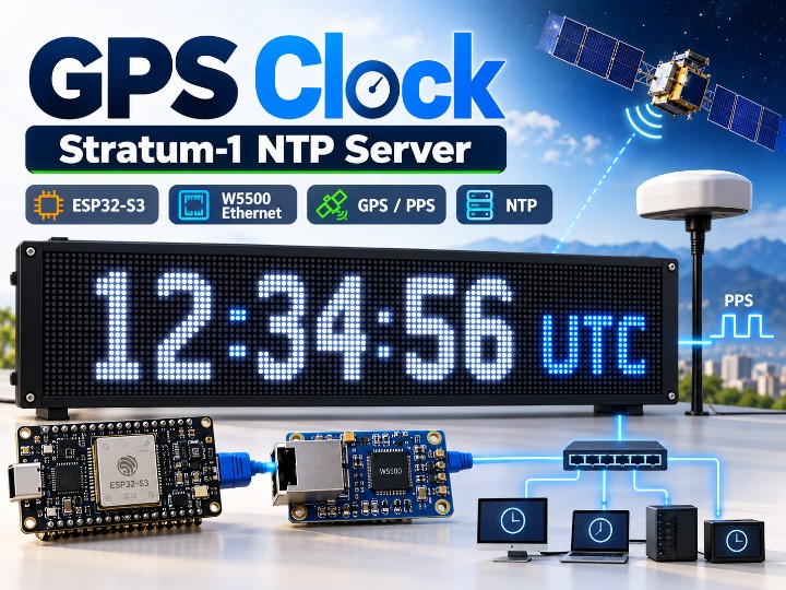
A GPS/PPS-based Stratum-1 NTP server using ESP32-S3 and WIZnet W5500 Ethernet to distribute accurate time over a local network.
0
Components
Hardware components
WIZnet - W5500
x 1

Espressif - ESP32
x 1
Project description
GPS Clock: Stratum-1 NTP Server with ESP32-S3, GPS/PPS, and W5500 Ethernet

CLOCK_ESP32_GPS_MATRIX는 ESP32-S3, GPS/PPS, WIZnet W5500 Ethernet을 이용해 384×64 HUB75 Wall Clock과 Local Network용 Stratum-1 NTP Server를 구현한 프로젝트입니다.
GPS의 NMEA Data가 날짜와 시간을 제공하고, PPS Signal이 정확한 1초 기준을 제공합니다. ESP32-S3는 이 정보를 이용해 NTP Response를 생성하고, W5500은 UDP Port 123을 통해 Local Network의 NTP Client에 시간을 전달합니다.
전체 구조는 다음과 같습니다.
GPS Satellite
→ GPS Module
→ NMEA + PPS
→ ESP32-S3
→ W5500 Ethernet
→ Local Network
→ NTP Clients
이 프로젝트는 Wi-Fi를 사용하지 않고 W5500 Ethernet을 Network Interface로 사용합니다.
Project Overview

주요 Hardware 구성은 다음과 같습니다.
- ESP32-S3 DevKitC-1
- WIZnet W5500 SPI Ethernet Module
- GPS Module with PPS Output
- 3 × HUB75 P2.5 LED Panels
- 384×64 Total Display Resolution
- 5 V Power Supply
Display는 128×64 pixel Panel 3개를 가로로 연결해 구성합니다.
따라서 전체 Resolution은:
128 × 3 = 384 px
즉,
384 × 64 px
입니다.
GPS and PPS Timing
GPS Receiver는 두 종류의 Timing Data를 제공합니다.
NMEA
NMEA Data는 날짜와 시간 정보를 제공합니다.
GPS Serial Data는 9600 baud로 수신됩니다.
GPS RX는:
- GPIO17
을 사용합니다.
PPS
PPS(Pulse Per Second)는 정확한 1초 Timing Reference를 제공합니다.
PPS는:
- GPIO21
에 연결되며 Rising Edge Hardware Interrupt로 처리됩니다.
두 Signal의 역할은 다음과 같이 구분할 수 있습니다.
NMEA = Date and Time Information
PPS = Precise One-Second Timing Reference
ESP32-S3는 PPS 발생 시점과 내부 Timing 정보를 이용해 NTP Timestamp를 생성합니다.
W5500 Ethernet Interface
W5500은 ESP32-S3와 SPI로 연결됩니다.
Pin Mapping은 다음과 같습니다.
| W5500 Signal | ESP32-S3 GPIO |
|---|---|
| SCK | GPIO13 |
| MISO | GPIO12 |
| MOSI | GPIO11 |
| CS | GPIO14 |
| RST | GPIO9 |
| INT | GPIO10 |
이 프로젝트에서는 Wi-Fi를 사용하지 않고 W5500 Ethernet을 Network Communication에 사용합니다.
Firmware는 Arduino Ethernet Library를 사용하며 W5500 Support가 명시되어 있습니다.
NTP Server Operation
이 프로젝트의 핵심 Network 기능은 Stratum-1 NTP Server입니다.
NTP Server는:
UDP Port 123
을 사용합니다.
전체 Data Flow는 다음과 같습니다.
NTP Client
→ W5500 Ethernet
→ ESP32-S3
→ NTP Response
→ W5500 Ethernet
→ NTP Client
ESP32-S3는 GPS/PPS Timing을 기준으로 NTP Response를 생성합니다.
W5500은 UDP Communication을 위한 Wired Ethernet Network Path를 제공합니다.
이 구조를 통해 외부 Internet NTP Server에 의존하지 않고 Local Network의 Client가 이 장치를 Time Source로 사용할 수 있습니다.
W5500 Hardware Socket Usage
이 프로젝트는 W5500을 단순한 Raw Ethernet Interface로만 사용하는 구조와 다릅니다.
PlatformIO Configuration에는 Arduino Ethernet Library와 W5500 사용 설정이 포함되어 있습니다.
Firmware에서는 UDP Communication을 위해 Ethernet Library를 사용합니다.
따라서 Network Path는 다음과 같이 이해할 수 있습니다.
ESP32-S3
→ Arduino Ethernet Library
→ W5500 Hardware UDP Socket
→ Ethernet Network
이 구조에서 W5500은 NTP UDP Communication의 Network Socket 처리에 직접 사용됩니다.
HUB75 LED Display
Display는 HUB75 P2.5 Panel 3개로 구성됩니다.
각 Panel은:
128 × 64 px
이며 3개를 연결해:
384 × 64 px
Display를 구성합니다.
화면에는 다음 정보가 표시됩니다.
- Local Time
- UTC
- Date
- Selected World Cities
- GPS Status
- PPS Status
- Satellite Count
단순 NTP Server에 그치지 않고 실제 사용자에게 시간을 보여주는 Wall Clock Application까지 포함되어 있습니다.
Web Dashboard
Clock 설정은 Web Dashboard에서도 변경할 수 있습니다.
Web Dashboard는 Port 80을 사용합니다.
설정 가능한 항목은 다음과 같습니다.
- Daylight Saving Time
- Center Brightness
- Side Brightness
- World City Selection
- Firmware OTA Update
설정값은 Restart 이후에도 유지될 수 있도록 저장됩니다.
DHCP가 실패하면 자동으로 Static IP로 전환하는 기능도 포함되어 있습니다.
OTA Firmware Update
Firmware는 Browser를 통한 OTA Update 기능을 제공합니다.
OTA Page는 HTTP Basic Authentication으로 보호됩니다.
현재 Prototype에서는 Default Credential이 설정되어 있기 때문에 신뢰할 수 없는 Network에서 사용할 경우 Credential을 변경해야 합니다.
OTA는 Remote Firmware Update 기능이기 때문에 Production 환경에서는 기본 인증 정보를 그대로 사용하지 않는 것이 중요합니다.
Network Architecture
이 프로젝트는 Wi-Fi를 사용하지 않습니다.
따라서 Network Path는 다음과 같이 단순합니다.
ESP32-S3
→ W5500 Ethernet
→ Local Network
ESP32-S3가 Wi-Fi 기능을 지원하더라도 실제 Project Architecture에서는 W5500 Ethernet만 사용합니다.
Power
System Power는 5 V를 사용합니다.
3개의 HUB75 Panel을 구동하기 위해 약 4 A Peak Current를 고려하도록 문서화되어 있습니다.
Display System이 포함되어 있기 때문에 일반적인 소형 IoT Sensor보다 높은 전류를 요구하는 프로젝트입니다.
Concrete Technical Details
이 프로젝트에서 확인할 수 있는 주요 기술 정보는 다음과 같습니다.
- ESP32-S3 DevKitC-1
- W5500 SPI Ethernet Module
- GPS Module with PPS
- GPS NMEA: 9600 baud
- GPS RX: GPIO17
- GPS PPS: GPIO21
- W5500 SCK: GPIO13
- W5500 MISO: GPIO12
- W5500 MOSI: GPIO11
- W5500 CS: GPIO14
- W5500 Reset: GPIO9
- W5500 Interrupt: GPIO10
- NTP: UDP Port 123
- Web Dashboard: Port 80
- 3 × 128×64 HUB75 Panels
- Total Resolution: 384×64
- 5 V Power
- Approximately 4 A Peak Current
이처럼 MCU, GPS, Ethernet, Network Port, Pin Mapping, Display, Power 정보가 모두 구체적으로 공개되어 있어 시스템 구조를 쉽게 확인할 수 있습니다.
Current Project Status
이 프로젝트는 현재 Work in Progress 상태의 Functional Prototype입니다.
현재 Hardware는 Dupont Wire 기반 Prototype이며, ESP32-S3, W5500, GPS Connector를 하나로 통합한 Dedicated PCB는 Roadmap 단계입니다.
따라서 현재 공개된 GPIO Mapping은 향후 PCB Revision에서 변경될 수 있습니다.
현재 상태를 완성된 Commercial Product로 보기보다는, 실제 동작하는 Prototype과 차기 Dedicated PCB 설계를 함께 진행하는 Open-Source Project로 보는 것이 적절합니다.
Why This Project Is Interesting
이 프로젝트를 선정한 이유는 W5500이 단순히 Device를 Network에 연결하는 역할을 넘어서 정확한 시간을 Local Network 전체에 배포하는 Time Synchronization Infrastructure에 사용된다는 점입니다.
전체 구조는 다음과 같습니다.
GPS Satellite
→ GPS/PPS
→ ESP32-S3
→ W5500 UDP Network
→ Local Network
→ NTP Client
또한 다음과 같은 구체적인 Evidence가 공개되어 있습니다.
- W5500 SPI Pin Mapping
- GPS PPS Interrupt
- NTP UDP Port 123
- Arduino Ethernet Library
- 384×64 Display Resolution
- Power Requirement
- Web Dashboard
- OTA Update
- Current Prototype Limitation
Industrial Gateway나 일반 Sensor Application과는 다른 Time Synchronization이라는 새로운 W5500 Application을 보여준다는 점도 흥미롭습니다.
Conclusion
CLOCK_ESP32_GPS_MATRIX는 ESP32-S3, GPS/PPS, W5500 Ethernet, HUB75 LED Matrix를 결합한 GPS Clock이자 Stratum-1 NTP Server 프로젝트입니다.
GPS가 Date와 Time Data를 제공하고 PPS가 정확한 Timing Reference를 제공합니다.
ESP32-S3는 이 정보를 바탕으로 NTP Response를 생성하며, W5500 Ethernet을 통해 Local Network의 Client에 Time Data를 전달합니다.
동일한 Ethernet Network는 Web Dashboard와 OTA Firmware Update에도 사용됩니다.
이 프로젝트는 W5500이 Time Synchronization Application에서 NTP Network Communication을 담당하는 구체적인 사례라는 점에서 의미가 있습니다.
GPS Clock: Stratum-1 NTP Server with ESP32-S3, GPS/PPS, and W5500 Ethernet
CLOCK_ESP32_GPS_MATRIX combines an ESP32-S3, GPS/PPS, WIZnet W5500 Ethernet, and a 384×64 HUB75 display to create both a wall clock and a local Stratum-1 NTP server.
GPS NMEA data provides date and time information, while the PPS signal provides a precise one-second timing reference. The ESP32-S3 generates NTP responses, and the W5500 distributes the timing data to local network clients over UDP port 123.
The overall architecture is:
GPS Satellite
→ GPS Module
→ NMEA + PPS
→ ESP32-S3
→ W5500 Ethernet
→ Local Network
→ NTP Clients
The project does not use Wi-Fi for network communication.
Project Overview
The main hardware components are:
- ESP32-S3 DevKitC-1
- WIZnet W5500 SPI Ethernet module
- GPS module with PPS output
- 3 × HUB75 P2.5 LED panels
- 384×64 total display resolution
- 5 V power supply
Each HUB75 panel has a resolution of 128×64 pixels.
Three panels are chained horizontally:
128 × 3 = 384 pixels
for a total display resolution of:
384 × 64 pixels
GPS and PPS Timing
The GPS module provides two timing signals.
NMEA
NMEA provides date and time information.
The GPS serial data is received at:
9600 baud
GPS RX uses:
- GPIO17
PPS
PPS provides the precise one-second timing reference.
The PPS signal uses:
- GPIO21
and is captured through a rising-edge hardware interrupt.
The roles are:
NMEA = Date and Time Information
PPS = Precise One-Second Timing Reference
The ESP32-S3 uses these signals to generate the timing information required for NTP responses.
W5500 Ethernet Interface
The W5500 is connected to the ESP32-S3 through SPI.
| W5500 Signal | ESP32-S3 GPIO |
|---|---|
| SCK | GPIO13 |
| MISO | GPIO12 |
| MOSI | GPIO11 |
| CS | GPIO14 |
| RST | GPIO9 |
| INT | GPIO10 |
The project uses wired W5500 Ethernet rather than Wi-Fi.
The firmware is built with the Arduino Ethernet library and explicit W5500 support.
NTP Server Operation
The system operates as a Stratum-1 NTP server.
NTP communication uses:
UDP Port 123
The data flow is:
NTP Client
→ W5500 Ethernet
→ ESP32-S3
→ NTP Response
→ W5500 Ethernet
→ NTP Client
The ESP32-S3 generates NTP responses using the GPS/PPS timing reference.
The W5500 provides the wired UDP network path used to distribute that timing information to local clients.
W5500 Hardware Socket Usage
This implementation uses the Arduino Ethernet library with explicit W5500 support.
UDP communication therefore operates through the W5500 network socket path.
The architecture can be represented as:
ESP32-S3
→ Arduino Ethernet Library
→ W5500 Hardware UDP Socket
→ Ethernet Network
This makes the W5500 part of the actual NTP network communication path rather than only a raw Ethernet frame interface.
HUB75 LED Display
The display uses three HUB75 P2.5 panels.
Each panel provides:
128 × 64 pixels
Three panels create:
384 × 64 pixels
The display can show:
- local time
- UTC
- date
- selected world cities
- GPS status
- PPS status
- satellite count
This gives the project a visible end application in addition to the NTP server function.
Web Dashboard
The project includes a browser-based dashboard on:
Port 80
The dashboard can configure:
- daylight saving time
- center brightness
- side brightness
- selected world cities
- OTA firmware updates
The project also supports automatic static-IP fallback if DHCP fails.
OTA Firmware Update
Firmware can be updated through the web interface.
The OTA page uses HTTP Basic Authentication.
The current prototype includes default credentials, which should be changed before use on an untrusted network.
This limitation is important because the OTA page can remotely update the firmware.
Network Architecture
The project explicitly does not use Wi-Fi for network communication.
The active network path is:
ESP32-S3
→ W5500 Ethernet
→ Local Network
The presence of Wi-Fi capability in the ESP32-S3 does not change the actual project architecture.
Power
The system uses a 5 V power supply.
The documentation recommends allowing approximately 4 A peak current for the three LED panels.
Concrete Technical Details
The project provides multiple source-verifiable details:
- ESP32-S3 DevKitC-1
- W5500 SPI Ethernet module
- GPS with PPS output
- GPS NMEA at 9600 baud
- GPS RX on GPIO17
- PPS on GPIO21
- W5500 SCK on GPIO13
- W5500 MISO on GPIO12
- W5500 MOSI on GPIO11
- W5500 CS on GPIO14
- W5500 reset on GPIO9
- W5500 interrupt on GPIO10
- NTP on UDP port 123
- web dashboard on port 80
- three 128×64 HUB75 panels
- 384×64 total display resolution
- 5 V supply
- approximately 4 A peak current
Current Project Status
The project is currently a work-in-progress functional prototype.
The present hardware uses temporary Dupont-wire connections.
A dedicated PCB integrating the ESP32-S3, W5500, and GPS connector is planned in the project roadmap.
As a result, the current GPIO mapping may change in a future PCB revision.
The project should therefore be understood as a working open-source prototype rather than a finished commercial product.
Why This Project Is Interesting
The project shows the W5500 being used as part of a time synchronization infrastructure.
The architecture is:
GPS Satellite
→ GPS/PPS
→ ESP32-S3
→ W5500 UDP Network
→ Local Network
→ NTP Clients
The project also provides strong technical evidence including:
- W5500 SPI pin mapping
- GPS PPS interrupt
- NTP UDP port 123
- Arduino Ethernet library configuration
- display resolution
- power requirement
- web dashboard
- OTA update
- prototype limitations
This makes it a distinctive W5500 application beyond typical industrial gateway or sensor use cases.
Conclusion
CLOCK_ESP32_GPS_MATRIX combines an ESP32-S3, GPS/PPS, W5500 Ethernet, and HUB75 LED matrix to create a GPS clock and Stratum-1 NTP server.
GPS provides date and time information, PPS provides the precise timing reference, and the ESP32-S3 generates NTP responses.
The W5500 carries the timing data over the local Ethernet network to NTP clients.
The same Ethernet connection also supports the web dashboard and OTA firmware update.
Overall, the project demonstrates a clear W5500 application in local network time synchronization.

