NEXTuino PEAK CORE — Compact ATmega2560 Industrial PLC
NEXTuino PEAK CORE: The New Name for CONTROLLINO MAXI, and How a W5100 Puts an 8 KB AVR on the Network
0
Components
Hardware components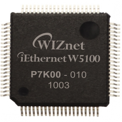
WIZnet - W5100
x 1

Project description
Summary
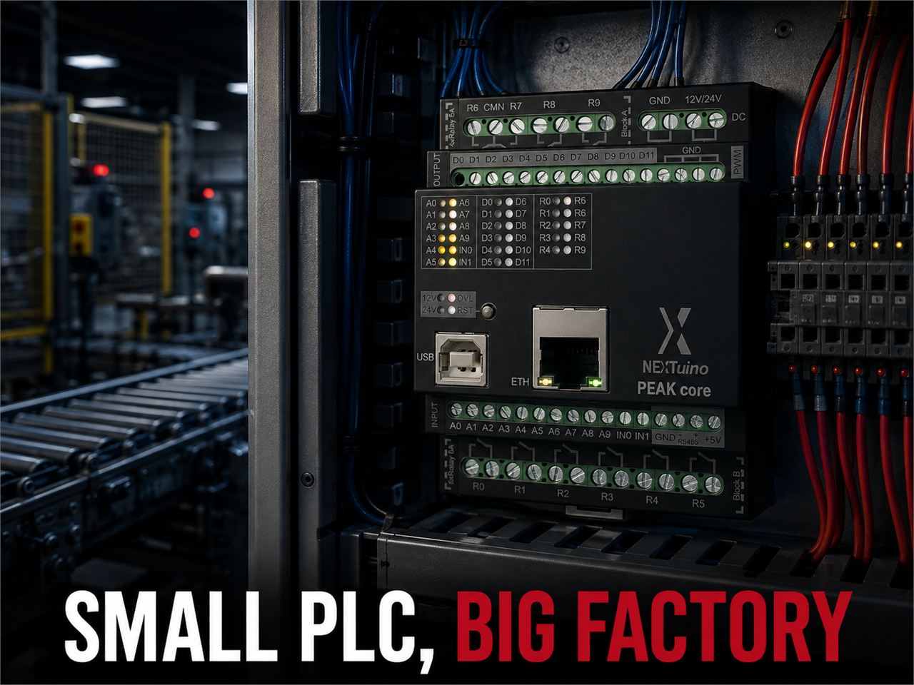
NEXTuino PEAK CORE is a DIN-rail PLC built on the ATmega2560. The maker's family overview maps it to the former CONTROLLINO MAXI Pure. A 2026 product change notice (PCN) confirms that only the name and part number changed from the old 100.100.10; the circuit and firmware are unchanged. Ethernet is handled by a WIZnet W5100. Because this chip processes TCP/IP in hardware (TOE), an 8-bit MCU with only 8 KB of SRAM can still act as a Modbus TCP server or an HTTP client.

→ Product page: https://www.nextuino.com/products/peak/core
Overview
PEAK CORE is a compact PLC aimed at OEM machine builders and panel builders. It fits 12 digital inputs (10 of them analog-capable), 12 transistor outputs, 10 relay outputs, RS-485 and Ethernet into a 72 × 90 × 62 mm housing. You program it in the Arduino IDE with the usual setup()/loop().
CORE in the name means the variant without Arduino pin headers. The maker states that "MCU and I/O mapping are identical," so PEAK firmware runs unchanged. Dropping the headers reduces board height and BOM cost. It suits production machines that will never take a shield.
The same hardware has already appeared on maker.wiznet.io several times under the name CONTROLLINO MAXI. This article covers what those posts left out: how the name changed, what the W5100 does on an 8 KB MCU, and how to budget its four sockets.
→ Earlier introduction: https://maker.wiznet.io/irina/resellers/controllino-maxi/
→ Sibling variant: https://maker.wiznet.io/bruno/resellers/controllino-maxi-power-automation-1/
Why the Name Changed: From CONTROLLINO to NEXTuino
Lineage
| When | What happened | Source |
|---|---|---|
| Launch date unconfirmed | Conelcom GmbH of Innsbruck, Austria, releases the Arduino-compatible PLC CONTROLLINO (MINI, MAXI, MEGA) | Manufacturer line in CONTROLLINO manuals |
| 2024-10-31 | Industrial Shields (Boot & Work Corp) of Barcelona, Spain, takes over exclusive production and marketing of the CONTROLLINO brand. Founder Marco Riedesser keeps designing products | Industry report (automation.com); company name from the PCN header |
| Effective 2026-05-01 | Industrial Shields issues PCN-IS-2026-001 (dated 2026-07-08), moving CONTROLLINO-compatible part numbers to 12-digit NEXTuino part numbers | PCN document |
→ PCN document (RS document server): https://docs.rs-online.com/1718/A700000015864598.pdf
→ Partnership report: https://www.automation.com/article/agreement-industrial-shields-controllino
What the PCN Says
The PCN's impact table lists Form, Fit, Function, hardware revision, software/firmware, pricing and lead time as "No change," and states it is a part number update only. The mapping for the PEAK line and CREST CORE is below.
| Old MPN | NEXTuino name | New MPN |
|---|---|---|
| 100.100.00 | NEXTuino PEAK | 042003000100 |
| 100.100.10 | NEXTuino PEAK CORE | 042003000200 |
| 100.101.00 | NEXTuino PEAK FLEX | 042003000300 |
| 100.101.10 | NEXTuino PEAK FLEX CORE | 042003000400 |
| 100.200.10 | NEXTuino CREST CORE | 042004000200 |
The PEAK CORE datasheet header also reads 042003000200 Rev.1.0, matching the new PCN part number. The maker's Family Overview datasheet maps PEAK CORE = CONTROLLINO MAXI Pure.
→ Family overview: https://www.nextuino.com/assets/datasheets/NEXTuino_Family_Overview_Datasheet.pdf
For readers, this means one thing. Code, pin macros and forum answers written for CONTROLLINO MAXI still apply to PEAK CORE. Some distributors still list the old name, so match on the part number when you order.
Standards
The datasheet lists EN 61010-1 / EN 61010-2-201 / EN 61131-2. EN 61131-2 covers functional and EMC requirements and tests for PLC equipment. EN 61010-2-201 covers electrical safety for control equipment. Certificate numbers are not published.
Architecture

The pin numbers come from the MAXI definitions in the CONTROLLINO library's Controllino.h.
- Ethernet:
CONTROLLINO_ETHERNET_CHIP_SELECT 70,CONTROLLINO_ETHERNET_INTERRUPT 71 - RTC:
CONTROLLINO_RTC_CHIP_SELECT 72,CONTROLLINO_RTC_INTERRUPT 73 - RS-485:
CONTROLLINO_RS485_TX 14,CONTROLLINO_RS485_RX 15,CONTROLLINO_RS485_DE 75,CONTROLLINO_RS485_nRE 76
→ Library: https://github.com/CONTROLLINO-PLC/CONTROLLINO_Library
The W5100 and the RTC share one SPI bus. Chip-select lines keep them apart, so firmware must handle the CS pins correctly. The Limitations section covers this.
Technology Background
Modbus RTU and Modbus TCP: Same Commands, Different Transport
- Concept: Modbus is an application-layer protocol that defines which registers to read and write. The command part (PDU: function code + data) is identical in RTU and TCP. Only the transport differs
- RTU: Over serial (RS-485), a frame is slave address + PDU + CRC-16. Silent intervals between characters mark frame boundaries
- TCP: Over a TCP connection on port 502, a frame is a 7-byte MBAP header + PDU. TCP handles error detection and retransmission, so no CRC is added
- Role in this product: PEAK CORE is a compact PLC with both RS-485 (RTU) and Ethernet (TCP). It can bridge both sides: poll field meters over RS-485 and expose the same registers to SCADA or HMI over Ethernet. The OpenPLC Editor firmware source has a branch that includes
Controllino.hwhenCONTROLLINO_MAXIorCONTROLLINO_MEGAis defined
→ Modbus specifications: https://www.modbus.org/modbus-specifications
→ OpenPLC Editor source: https://github.com/Autonomy-Logic/openplc-editor
EN 61131-2 and EN 61010-2-201: What PLC Standards Leave in a Datasheet
- Concept: IEC/EN 61131-2 defines functional requirements (power, I/O characteristics and so on), EMC requirements and their verification tests for PLC equipment. Since the 2017 edition, safety requirements have moved to IEC 61010-2-201
- Core idea: A typical microcontroller board talks about "3.3 V logic." PLC standards ask where 0 ends and 1 begins at 12/24 V field voltage, and how much ESD and surge the device survives
- Role in this product: The datasheet numbers answer the questions these two standards ask
- 24 V range inputs: 0–7.2 V is Low, 18–26.4 V is High, input current below 3 mA
- ESD: ±4 kV contact / ±8 kV air
- Shock: 15 g, 11 ms half-sine, all three axes
- Vibration: 1.75 mm amplitude at 5–9 Hz, 0.5 g at 9–150 Hz (sine)
- Pollution degree PD2, altitude up to 2000 m
These numbers are the difference between a PLC and "an Arduino board in a case."
Technical Highlights
- CORE without headers: Same I/O mapping as PEAK, minus the pin headers. Inside a machine that never takes a shield, height and part count go down
- 12 V / 24 V with LED indication: Two power LEDs turn green or orange depending on the input range (10.2–15.0 V / 20.4–30.0 V). You can check the supply range on site at a glance
- Isolated relays, non-isolated DI/DO: Relays have 3000 V AC coil-to-contact isolation for 1 minute. Digital inputs and transistor outputs are marked "no galvanic insulation," so keep them on a common ground reference
- PWM and relays: Transistor outputs support PWM at 5–95 % duty. When relays are driven by PWM, the datasheet says they switch on above 30 % duty
- Built-in RTC: An RV-2123 RTC on SPI lets you run time-based schedules even without Ethernet
- No RS-485 termination: Add an external 120 Ω resistor if the PLC sits at the end of the bus (datasheet: "no termination inside")
Where WIZnet Fits: Taking TCP off an 8 KB SRAM
TOE Verdict: Yes
PEAK CORE's Ethernet runs on the W5100's hardware TCP/IP (TOE). The evidence:
- The product page's communication section explicitly lists "Ethernet (W5100)"
- Since CONTROLLINO BSP 3.0.0, the board uses the standard Arduino
Ethernetlibrary (library README, FAQ 9). That library has no software stack such as lwIP. It drives the WIZnet chip's hardware sockets directly through registers - The library's
socket.cppcontainsif (chip == 51) maxindex = 4;. On a W5100 (chip ID 51), it uses at most four hardware sockets
W5100 key specs (per WIZnet's official documentation)
| Item | Value |
|---|---|
| Hardware sockets | 4 simultaneous |
| Internal buffer | 16 KB (8 KB TX + 8 KB RX, each split across sockets) |
| Protocols in hardware | TCP, UDP, ICMP, IGMPv1/v2, IPv4, ARP, PPPoE |
| PHY | Integrated 10BASE-T / 100BASE-TX, auto-negotiation |
| Host interface | SPI or parallel bus |
→ W5100 documentation: https://docs.wiznet.io/Product/Chip/Ethernet/W5100
How One Modbus TCP Request Is Handled
Let's run PEAK CORE as a Modbus TCP server (port 502) and follow a SCADA host reading 10 input registers.
- SCADA opens a connection to port 502. The W5100 receives the SYN and returns the SYN-ACK. The MCU only sees the socket status register change to
ESTABLISHED - The request frame arrives (7-byte MBAP + function code 0x04 + start address + quantity = 12 bytes). The W5100 strips the IP and TCP headers, verifies checksums and sends the ACK. Only the 12-byte payload lands in the RX buffer
- The ATmega2560 reads those 12 bytes over SPI. It parses the function code, reads A0–A9 with
analogRead()and builds the response PDU. That is all the MCU does - The MCU writes the response into the TX buffer and issues a "send" command. The W5100 builds the TCP segment, sequence numbers and checksums, and retransmits if the peer does not ACK
- When SCADA closes the connection, the library issues one disconnect command and the W5100 handles the FIN exchange. The socket returns to a reusable state
Think of the W5100 as the security office at a factory gate. It checks visitors in (handshake), verifies badges (checksums), signs for deliveries (ACKs) and resends what didn't arrive (retransmission). The plant manager (the ATmega2560) only gets a single note: "please send me the values of 10 registers." The manager writes the answer and sends it back down.
Without This Chip
If you paired the 8-bit AVR with a controller that only has MAC+PHY, the TCP state machine, retransmission timers and packet buffers would all have to run inside the MCU's 8 KB of SRAM. That memory would then be shared with the Modbus register map, the RS-485 buffers and the user's ladder logic [Inferred]. The W5100 keeps its own 16 KB of packet buffer on-chip, so the MCU's SRAM stays almost entirely free for application logic.
Budgeting the Four Sockets
In the standard Ethernet library, EthernetServer hands its listening socket to a new client and then opens a fresh listening socket (available() in EthernetServer.cpp). So serving one concurrent client takes two sockets.
| Purpose | Sockets | Notes |
|---|---|---|
| Modbus TCP server, one connection | 1 | SCADA link |
| Modbus TCP server, waiting for the next client | 1 | The library reopens it automatically |
| NTP or HTTP client | 1 | Open briefly for time sync or cloud upload, then close |
| Spare | 1 | A second HMI or diagnostics |
Go past this budget and new connections are refused or must wait. If several upstream systems need data, consolidate polling into one or design so that no connection is held open for long.

Similar Projects on WIZnet Makers
- Connect a Controllino MAXI to Ubidots over HTTP: Same hardware (MAXI) and the same standard
Ethernet.hlibrary. It uploads the A0 value to the cloud and switches relay R0 from a dashboard. As the simplest form, one socket running an HTTP client, it shows how the "NTP or HTTP client" row in the budget table works in practice
→ Project link: https://maker.wiznet.io/teddy/projects/connect-a-controllino-maxi-to-ubidots-over-http/ - PoolMaster pool water regulation system: An open-source project that measures pH and ORP and controls chemical pumps. It supports both a CONTROLLINO MAXI and an Arduino Mega 2560 + Ethernet shield + relay shield. The same ATmega2560 code running on a DIY board and a commercial PLC backs up PEAK CORE's "your Arduino code as-is" claim
→ Project link: https://maker.wiznet.io/WIZnet/projects/connected-pool-water-regulation-system-poolmaster/ - M-Duino 42+ PLCs controlling 12 Arctic tanks: Four M-Duino 42+ units control 12 climate-experiment tanks in Svalbard, Norway. They come from the same Industrial Shields portfolio and use the same ATmega2560, but with a W5500 for Ethernet. This lets you compare how socket count changes with the chip at the same MCU class
→ Project link: https://maker.wiznet.io/mason/projects/12-arctic-tanks-four-water-conditions-m-duino-42-plcs-keep-each-on-target/
All three cases attach WIZnet hardware TCP/IP to an 8-bit ATmega2560 over SPI. The applications differ (cloud HTTP, water control, research tanks), but the network layer is solved the same way.
| Item | PEAK CORE | MAXI → Ubidots | PoolMaster | M-Duino 42+ tanks |
|---|---|---|---|---|
| Form | Commercial PLC (no headers) | Commercial PLC | DIY or commercial PLC | Commercial PLC |
| MCU | ATmega2560 | ATmega2560 | ATmega2560 | ATmega2560 |
| Ethernet chip | W5100 | W5100 (same MAXI) | W5100 on MAXI; depends on the shield on Mega | W5500 |
| Hardware sockets | 4 | 4 | 4 on MAXI | 8 |
| Upper protocol | Modbus TCP, HTTP, etc. (user's choice) | HTTP | MQTT (author's README) | WebSocket |
| Field bus | RS-485 | — | — | RS-485 |
The common pattern across these cases is "the 8-bit MCU runs the control logic, and a dedicated chip runs TCP/IP." PEAK CORE packages that structure in a header-free OEM form.
Use Cases
- Embedded controller for OEM machines: Packaging machines, dryers and washers that fit within 10 relays and 12 DI. Machine status goes out over Ethernet to an MES or HMI. Without headers, you save height inside the machine's control cabinet
- Continued production of CONTROLLINO MAXI designs: Machines already built on MAXI can keep sourcing the same hardware under the new part number without code changes. Only the part number and name in the BOM change
- Modbus RTU meters → Modbus TCP: A small gateway-plus-controller that polls several energy meters or temperature controllers over RS-485 and re-exposes their values as Modbus TCP registers on Ethernet
- OpenPLC training and small sites: The OpenPLC Editor source has branches for CONTROLLINO MAXI and MEGA, so uploading IEC 61131-3 ladder logic and monitoring it over Modbus TCP appears feasible [Inferred]
Limitations and Future Improvements
PEAK CORE carries an existing 8-bit PLC design forward under a new name. That continuity is its strength, and its limits come from the same generation.
Current limitations
- Four sockets: As the budget table shows, one server connection uses two. Running a web config page, Modbus TCP and MQTT at once is tight
- W5100 SPI efficiency: A comment in the standard library notes that the W5100 uses a 4-byte frame for every byte. It is likely a disadvantage for streaming large data, as opposed to periodic register exchange [Inferred]
- No TLS: The CONTROLLINO library README states that the hardware cannot do SSL/TLS encryption, so HTTPS is not possible. If you need a direct cloud link, put a gateway that handles TLS in front
- Shared SPI and CS handling: CONTROLLINO README FAQ 7 warns that floating CS lines for the RTC (PJ2) and the WIZnet chip (PJ3) can cause MISO contention. It recommends calling
Controllino_RTC_init()before using SPI. CORE has no headers, so external SPI devices are rare, but the rule still applies if your firmware drives SPI directly - Inconsistent published figures: The product page and the datasheet disagree
| Item | Product page | Datasheet (Rev.1.0) |
|---|---|---|
| Relay contacts | 10 A / 240 V AC | 6 A / 250 V AC, 30 V DC |
| Operating temperature | −10 to +55 °C | 0 to 55 °C |
| Ethernet access | "accessible via terminal blocks" | RJ45, 10/100 Mbps |
The CONTROLLINO library README also rates the MAXI relays at 230 V / 6 A. Designing to the datasheet values (6 A, 0 °C) is the safer choice.
Future improvements
Move to the W5500 generation: The M-Duino from the same Industrial Shields portfolio and the sibling NEXTuino BASE already use the W5500 (8 sockets) (socket count per WIZnet's official documentation). The standard
Ethernetlibrary auto-detects W5100, W5200 and W5500 (isW5100()/isW5500()inw5100.cpp), so a later revision could switch chips with little or no change to user code [Inferred]
→ W5500 documentation: https://docs.wiznet.io/Product/Chip/Ethernet/W5500Clean up published material: Aligning the web and datasheet figures left over from the rebrand, and naming the Ethernet chip in the datasheet, would make OEM design reviews easier
FAQ
Q1. Can I run CONTROLLINO MAXI code on PEAK CORE as-is?
The PCN states "No change" for both hardware and firmware. Pin macros (such as CONTROLLINO_R0) and Ethernet code should work unchanged. However, CORE has no pin headers, so code that uses header pins (such as X1) does not apply.
Q2. What do I install for development?
Install the CONTROLLINO board package from the Arduino IDE Boards Manager and use #include <Controllino.h>. For Ethernet, use the standard Ethernet.h.
Q3. What if four sockets are not enough? Consolidate server connections to a single upstream system, and open client tasks such as HTTP and NTP briefly, then close them. If that still falls short, it is time to look at a sibling product with a W5500 (8 sockets).
Q4. How does it differ from the NEXTuino BASE with a W5500? BASE is an RP2040 (264 KB SRAM) + W5500. PEAK CORE is an ATmega2560 (8 KB SRAM) + W5100. Both hand TCP/IP to the chip. They differ in socket count (8 vs. 4) and MCU headroom.
Q5. Which relay rating should I trust? Design to the 6 A / 250 V AC in datasheet Rev.1.0. Older CONTROLLINO documents also say 6 A. The common relay terminal is rated 6 A maximum as well.
→ Datasheet: https://www.nextuino.com/assets/datasheets/NEXTuino_PEAK_CORE_Datasheet.pdf
요약
NEXTuino PEAK CORE는 ATmega2560 기반 DIN 레일 PLC입니다. 제조사 제품군 개요의 CONTROLLINO 대응표에 따르면 옛 CONTROLLINO MAXI Pure에 해당하고, 2026년 품번 변경 통지(PCN)는 옛 품번 100.100.10에서 이름과 품번만 바뀌었을 뿐 회로·펌웨어는 그대로라고 밝힙니다. Ethernet은 WIZnet W5100이 맡습니다. 이 칩이 TCP/IP를 하드웨어로 처리(TOE) 하기 때문에, SRAM이 8 KB뿐인 8비트 MCU도 Modbus TCP 서버나 HTTP 클라이언트로 동작합니다.
→ 제품 페이지: https://www.nextuino.com/products/peak/core
개요
PEAK CORE는 OEM 장비 제작사와 패널 빌더를 겨냥한 소형 PLC입니다. 72 × 90 × 62 mm 크기에 디지털 입력 12개(그중 10개는 아날로그 겸용), 트랜지스터 출력 12개, 릴레이 출력 10개, RS-485, Ethernet을 담았습니다. 프로그래밍은 Arduino IDE에서 setup()/loop() 그대로 합니다.
이름의 CORE는 Arduino 핀헤더를 뺀 변형이라는 뜻입니다. 제조사는 "MCU와 I/O 매핑이 동일해 PEAK 펌웨어가 그대로 돈다"고 밝히고, 헤더를 빼서 높이와 BOM을 줄였다고 설명합니다. 실드로 확장할 일이 없는 양산 장비에 맞춘 구성입니다.
같은 하드웨어는 maker.wiznet.io에서 이미 CONTROLLINO MAXI라는 이름으로 여러 차례 소개됐습니다. 이 글은 그 글들이 다루지 않은 이름이 바뀐 경위, W5100이 8 KB MCU에서 맡는 일, 소켓 4개를 나눠 쓰는 법에 집중합니다.
→ 기존 소개 글: https://maker.wiznet.io/irina/resellers/controllino-maxi/
→ 형제 변형 글: https://maker.wiznet.io/bruno/resellers/controllino-maxi-power-automation-1/
이름이 바뀐 이유 — CONTROLLINO에서 NEXTuino까지
계보
| 시점 | 일 | 근거 |
|---|---|---|
| 출시 시점 확인 불가 | 오스트리아 인스브루크의 Conelcom GmbH가 Arduino 호환 PLC CONTROLLINO(MINI·MAXI·MEGA)를 내놓습니다 | CONTROLLINO 매뉴얼의 제조사 표기 |
| 2024-10-31 | 스페인 바르셀로나의 Industrial Shields(Boot & Work Corp)가 CONTROLLINO 브랜드의 독점 생산·마케팅을 넘겨받습니다. 창업자 Marco Riedesser는 설계에 계속 참여합니다 | 업계 보도(automation.com), 회사명은 PCN 머리글 |
| 2026-05-01 적용 | Industrial Shields가 PCN-IS-2026-001(2026-07-08 발행)로 CONTROLLINO 호환 품번을 NEXTuino 12자리 품번으로 바꿉니다 | PCN 원문 |
→ PCN 원문(RS 문서 서버): https://docs.rs-online.com/1718/A700000015864598.pdf
→ 제휴 보도: https://www.automation.com/article/agreement-industrial-shields-controllino
PCN이 말하는 것
PCN의 영향 평가표는 Form·Fit·Function·하드웨어 리비전·소프트웨어/펌웨어·가격·리드타임이 모두 "변경 없음" 이고, "품번만 바뀐다"고 명시합니다. PEAK 계열과 CREST CORE의 대응은 다음과 같습니다.
| 옛 품번 | NEXTuino 이름 | 새 품번 |
|---|---|---|
| 100.100.00 | NEXTuino PEAK | 042003000100 |
| 100.100.10 | NEXTuino PEAK CORE | 042003000200 |
| 100.101.00 | NEXTuino PEAK FLEX | 042003000300 |
| 100.101.10 | NEXTuino PEAK FLEX CORE | 042003000400 |
| 100.200.10 | NEXTuino CREST CORE | 042004000200 |
PEAK CORE 데이터시트 머리말의 품번도 042003000200 Rev.1.0으로 PCN의 새 품번과 같습니다. 제조사의 제품군 개요(Family Overview) 데이터시트는 PEAK CORE = CONTROLLINO MAXI Pure로 대응시킵니다.
→ 제품군 개요: https://www.nextuino.com/assets/datasheets/NEXTuino_Family_Overview_Datasheet.pdf
독자에게 의미하는 것은 하나입니다. CONTROLLINO MAXI용으로 쓴 코드, 핀 매크로, 포럼 답변이 PEAK CORE에서도 그대로 통합니다. 판매처에 따라 아직 옛 이름이 남아 있으니, 구매할 때는 품번으로 대조하는 편이 안전합니다.
규격 측면
데이터시트는 적용 규격으로 EN 61010-1 / EN 61010-2-201 / EN 61131-2를 적었습니다. EN 61131-2는 PLC 장비의 기능·EMC 요구사항과 시험을 다루는 규격이고, 61010-2-201은 제어 장비의 전기 안전 규격입니다. 인증서 번호는 공개 자료에서 확인되지 않습니다.
아키텍처
핀 번호는 CONTROLLINO 라이브러리의 Controllino.h MAXI 정의에서 확인했습니다.
- Ethernet:
CONTROLLINO_ETHERNET_CHIP_SELECT 70,CONTROLLINO_ETHERNET_INTERRUPT 71 - RTC:
CONTROLLINO_RTC_CHIP_SELECT 72,CONTROLLINO_RTC_INTERRUPT 73 - RS-485:
CONTROLLINO_RS485_TX 14,CONTROLLINO_RS485_RX 15,CONTROLLINO_RS485_DE 75,CONTROLLINO_RS485_nRE 76
→ 라이브러리: https://github.com/CONTROLLINO-PLC/CONTROLLINO_Library
W5100과 RTC가 SPI 버스 하나를 함께 씁니다. 칩 선택 핀으로 둘을 나누는 구조라 펌웨어가 CS 핀을 제대로 다뤄야 합니다. 이 내용은 「한계 및 개선 방향」에서 다룹니다.
기술 배경
Modbus RTU와 Modbus TCP — 같은 명령, 다른 운반 방식
- 개념: Modbus는 "어느 레지스터를 읽고 쓸지"를 정한 응용 계층 프로토콜입니다. 명령 부분(PDU: 기능 코드 + 데이터)은 RTU와 TCP가 같고, 운반 방식만 다릅니다
- RTU: 시리얼(RS-485) 위에서 슬레이브 주소 + PDU + CRC-16으로 프레임을 만들고, 문자 사이의 침묵 시간으로 프레임 경계를 판단합니다
- TCP: 포트 502의 TCP 연결 위에서 7바이트 MBAP 헤더 + PDU를 보냅니다. 오류 검출과 재전송은 TCP가 맡으므로 CRC를 붙이지 않습니다
- 이 제품에서의 역할: PEAK CORE는 RS-485(RTU)와 Ethernet(TCP)을 함께 갖춘 소형 PLC입니다. 현장 계측기는 RS-485로 묶고, 상위 SCADA나 HMI에는 Ethernet으로 같은 레지스터를 내보내는 양쪽 다리 역할이 가능합니다. OpenPLC 에디터의 펌웨어 소스에는
CONTROLLINO_MAXI·CONTROLLINO_MEGA일 때Controllino.h를 불러오는 분기가 있습니다
→ Modbus 규격: https://www.modbus.org/modbus-specifications
→ OpenPLC 에디터 소스: https://github.com/Autonomy-Logic/openplc-editor
EN 61131-2와 EN 61010-2-201 — PLC 장비 규격이 데이터시트에 남기는 흔적
- 개념: IEC/EN 61131-2는 PLC 장비의 기능 요구사항(전원·입출력 특성 등)과 EMC 요구사항, 그 검증 시험을 정한 규격입니다. 2017년판부터 안전 요구사항은 IEC 61010-2-201로 넘겼습니다
- 동작 원리의 핵심: 일반 마이크로컨트롤러 보드가 "3.3 V 로직"을 말한다면, PLC 규격은 12/24 V 필드 전압에서 어디까지가 0이고 어디부터 1인지, 정전기와 서지를 얼마나 견디는지를 묻습니다
- 이 제품에서의 역할: 데이터시트의 숫자들은 이 두 규격이 묻는 항목에 대한 답입니다
- 24 V 범위 입력: 0
7.2 V는 Low, 1826.4 V는 High, 입력 전류 3 mA 미만 - 정전기 방전: 접촉 ±4 kV / 기중 ±8 kV
- 충격: 15 g, 11 ms 반정현파, 3축 모두
- 진동: 5~9 Hz는 1.75 mm 진폭, 9~150 Hz는 0.5 g(정현파 기준)
- 오염도 PD2, 고도 2000 m 이하
- 24 V 범위 입력: 0
이 숫자들이 "Arduino 보드를 케이스에 넣은 것"과 PLC의 차이입니다.
기술 특징
- 헤더를 뺀 CORE: PEAK와 I/O 매핑이 같고 핀헤더만 없습니다. 실드를 꽂을 일이 없는 장비 안에서는 높이와 부품 수가 줄어듭니다
- 12 V / 24 V 공용 + LED로 판별: 전원 LED 두 개가 입력 전압 범위(10.2
15.0 V / 20.430.0 V)에 따라 초록·주황으로 바뀝니다. 현장에서 전원 범위를 바로 확인할 수 있습니다 - 릴레이는 절연, DI/DO는 비절연: 릴레이는 코일-접점 3000 V AC 1분 절연입니다. 디지털 입력과 트랜지스터 출력은 "no galvanic insulation" 으로 명시돼 있어 같은 접지 기준 안에서 써야 합니다
- PWM과 릴레이: 트랜지스터 출력은 듀티 5~95 % PWM을 지원합니다. 릴레이를 PWM으로 구동할 때는 듀티 30 % 초과에서 켜진다고 적혀 있습니다
- RTC 내장: SPI에 RV-2123 RTC가 있어 Ethernet 없이도 시각 기반 스케줄을 돌릴 수 있습니다
- RS-485는 종단 저항이 없습니다: 버스 끝단이면 120 Ω을 외부에 달아야 합니다(데이터시트 "no termination inside")
W5100이 맡는 일 — 8 KB SRAM에서 TCP를 덜어내기
TOE 판정: 사용함
PEAK CORE의 Ethernet은 W5100의 하드웨어 TCP/IP(TOE) 로 동작합니다. 근거는 다음과 같습니다.
- 제품 페이지의 통신 항목에 "Ethernet (W5100)" 이 명시돼 있습니다
- CONTROLLINO BSP 3.0.0부터 표준 Arduino
Ethernet라이브러리를 씁니다(라이브러리 README FAQ 9). 이 라이브러리는 lwIP 같은 소프트웨어 스택이 없고, WIZnet 칩의 하드웨어 소켓을 레지스터로 직접 다룹니다 - 라이브러리
socket.cpp에는if (chip == 51) maxindex = 4;가 있습니다. W5100(칩 ID 51)이면 하드웨어 소켓 4개까지만 쓴다는 뜻입니다
W5100 주요 사양(WIZnet 공식 문서 기준)
| 항목 | 값 |
|---|---|
| 하드웨어 소켓 | 4개 동시 |
| 내부 버퍼 | 16 KB (송신 8 KB + 수신 8 KB, 각각 소켓별로 배분) |
| 하드웨어 처리 프로토콜 | TCP, UDP, ICMP, IGMPv1/v2, IPv4, ARP, PPPoE |
| PHY | 10BASE-T / 100BASE-TX 내장, 자동 협상 |
| 호스트 인터페이스 | SPI 또는 병렬 버스 |
→ W5100 문서: https://docs.wiznet.io/Product/Chip/Ethernet/W5100
Modbus TCP 요청 하나가 처리되는 과정
PEAK CORE를 Modbus TCP 서버(포트 502) 로 두고, SCADA가 입력 레지스터 10개를 읽는 상황을 따라가 보겠습니다.
- SCADA가 포트 502로 연결을 요청합니다. SYN을 받고 SYN-ACK을 돌려 연결을 맺는 일은 W5100이 합니다. MCU는 소켓 상태 레지스터가
ESTABLISHED로 바뀐 것만 확인합니다 - 요청 프레임이 도착합니다(MBAP 7바이트 + 기능 코드 0x04 + 시작 주소 + 개수 = 12바이트). W5100이 IP·TCP 헤더를 벗기고 체크섬을 검사하고 ACK을 보낸 뒤, 12바이트 페이로드만 수신 버퍼에 남깁니다
- ATmega2560은 SPI로 12바이트를 읽습니다. 기능 코드를 해석하고
analogRead()로 A0~A9를 읽어 응답 PDU를 만듭니다. MCU가 하는 일은 여기까지입니다 - MCU가 응답 바이트를 송신 버퍼에 쓰고 "보내라" 명령을 줍니다. TCP 세그먼트 구성, 시퀀스 번호, 체크섬, 상대가 ACK을 안 보내면 재전송하는 일은 W5100이 합니다
- SCADA가 연결을 닫으면 라이브러리가 끊기 명령을 한 번 주고, FIN 교환은 W5100이 처리합니다. 소켓은 다시 쓸 수 있는 상태로 돌아갑니다
비유하면 W5100은 공장 정문의 경비실입니다. 방문객 확인(핸드셰이크), 출입증 확인(체크섬), 받은 서류의 수령증(ACK), 상대가 못 받았을 때 다시 보내는 일(재전송)은 경비실이 처리합니다. 공장장(ATmega2560)에게는 "레지스터 10개 값을 알려 달라"는 쪽지 한 장만 올라옵니다. 공장장은 쪽지에 답만 써서 내려보내면 됩니다.
이 칩이 없었다면
8비트 AVR에 MAC+PHY만 있는 컨트롤러를 붙이면, TCP 상태 기계, 재전송 타이머, 패킷 버퍼를 MCU의 8 KB SRAM 안에서 직접 돌려야 합니다. 그러면 Modbus 레지스터 맵, RS-485 버퍼, 사용자 래더 로직과 메모리를 나눠 써야 합니다 [추정]. W5100은 패킷 버퍼 16 KB를 칩 안에 따로 갖고 있어서, MCU의 SRAM은 응용 로직에 거의 그대로 남습니다.
소켓 4개 예산 짜기
표준 Ethernet 라이브러리의 EthernetServer는 클라이언트가 붙으면 대기하던 소켓을 그 연결에 넘기고, 대기 소켓을 새로 하나 엽니다(EthernetServer.cpp의 available()). 따라서 서버에 동시 접속 1개를 받으려면 소켓 2개가 필요합니다.
| 용도 | 소켓 | 비고 |
|---|---|---|
| Modbus TCP 서버 — 접속 1개 | 1 | SCADA 연결 |
| Modbus TCP 서버 — 다음 접속 대기 | 1 | 라이브러리가 자동으로 다시 엶 |
| NTP 또는 HTTP 클라이언트 | 1 | 시각 동기화나 클라우드 전송은 짧게 열고 닫기 |
| 예비 | 1 | 두 번째 HMI 접속 또는 진단용 |
이 예산을 넘기면 새 연결이 거부되거나 기존 연결을 기다려야 합니다. 상위 시스템이 여러 대라면 폴링하는 쪽을 하나로 모으거나, 연결을 오래 붙잡지 않도록 설계하는 편이 안정적입니다.
WIZnet Makers 유사 사례
- Controllino MAXI를 HTTP로 Ubidots에 연결하기 — 같은 하드웨어(MAXI)에 같은 표준
Ethernet.h라이브러리를 쓰고, A0 값을 클라우드로 올리고 릴레이 R0을 대시보드에서 켭니다. 소켓 하나로 HTTP 클라이언트를 돌리는 가장 단순한 형태로, 위 예산표의 "NTP 또는 HTTP 클라이언트" 칸이 실제로 어떻게 쓰이는지 보여줍니다
→ 프로젝트 링크: https://maker.wiznet.io/teddy/projects/connect-a-controllino-maxi-to-ubidots-over-http/ - PoolMaster 수영장 수질 조절 시스템 — pH·ORP를 재고 약품 펌프를 제어하는 오픈소스 프로젝트입니다. CONTROLLINO MAXI와 Arduino Mega 2560 + Ethernet 실드 + 릴레이 실드 두 구성을 모두 지원합니다. 같은 ATmega2560 코드가 DIY 보드와 상용 PLC 양쪽에서 돈다는 점이 PEAK CORE의 "Arduino 코드 그대로"라는 주장을 실제로 보여줍니다
→ 프로젝트 링크: https://maker.wiznet.io/WIZnet/projects/connected-pool-water-regulation-system-poolmaster/ - 북극 수조 12개를 제어하는 M-Duino 42+ PLC — 노르웨이 스발바르의 기후 실험 수조 12개를 M-Duino 42+ 4대로 제어합니다. 같은 Industrial Shields 제품군에 같은 ATmega2560이지만 Ethernet은 W5500입니다. 같은 MCU 급에서 칩에 따라 소켓 수가 어떻게 달라지는지 비교할 수 있습니다
→ 프로젝트 링크: https://maker.wiznet.io/mason/projects/12-arctic-tanks-four-water-conditions-m-duino-42-plcs-keep-each-on-target/
세 사례 모두 8비트 ATmega2560에 WIZnet 하드웨어 TCP/IP를 SPI로 붙인 구조입니다. 응용(클라우드 HTTP, 수질 제어, 연구용 수조)이 달라도 네트워크 계층은 같은 방식으로 풀었습니다.
| 항목 | PEAK CORE | MAXI → Ubidots | PoolMaster | M-Duino 42+ 수조 |
|---|---|---|---|---|
| 형태 | 상용 PLC (헤더 없음) | 상용 PLC | DIY 또는 상용 PLC | 상용 PLC |
| MCU | ATmega2560 | ATmega2560 | ATmega2560 | ATmega2560 |
| Ethernet 칩 | W5100 | W5100 (MAXI 동일) | MAXI 구성은 W5100, Mega 구성은 실드에 따라 다름 | W5500 |
| 하드웨어 소켓 | 4 | 4 | MAXI 구성은 4 | 8 |
| 상위 프로토콜 | Modbus TCP·HTTP 등 (사용자 선택) | HTTP | MQTT (원저자 README) | WebSocket |
| 필드 버스 | RS-485 | — | — | RS-485 |
세 사례에서 공통으로 보이는 구성은 "8비트 MCU는 제어 로직만 맡고, TCP/IP는 전용 칩에 맡긴다"는 것입니다. PEAK CORE는 그 구조를 헤더 없는 OEM 형태로 정리한 제품입니다.
어디에 쓰나
- OEM 장비의 내장 제어기: 포장기, 건조기, 세척기처럼 릴레이 10개와 DI 12개 안에서 끝나는 장비에 넣고, 장비 상태는 Ethernet으로 상위 MES나 HMI에 내보냅니다. 헤더가 없어 장비 안 전장함 높이를 아낄 수 있습니다
- CONTROLLINO MAXI 기반 설계의 계속 생산: 이미 MAXI로 만든 장비라면 코드 수정 없이 같은 하드웨어를 새 품번으로 계속 조달할 수 있습니다. 바뀌는 것은 BOM의 품번과 이름뿐입니다
- Modbus RTU 계측기 → Modbus TCP 묶음: 전력량계나 온도 조절기 여러 대를 RS-485로 폴링하고, 그 값을 Ethernet 쪽 Modbus TCP 레지스터로 다시 내보내는 소형 게이트웨이 겸 제어기
- OpenPLC 교육·소규모 현장: OpenPLC 에디터 소스에 CONTROLLINO MAXI·MEGA용 분기가 있어, IEC 61131-3 래더로 짠 로직을 올리고 Modbus TCP로 감시하는 구성이 가능할 것으로 보입니다 [추정]
한계 및 개선 방향
PEAK CORE는 기존 8비트 PLC 설계를 이름만 바꿔 이어가는 제품입니다. 그 연속성이 장점이고, 한계도 그 세대에서 옵니다.
현재 한계
- 소켓 4개: 위 예산표처럼 서버 접속 하나에 두 개가 들어갑니다. 웹 설정 페이지, Modbus TCP, MQTT를 한꺼번에 돌리기에는 빠듯합니다
- W5100 SPI 효율: 표준 라이브러리 주석은 W5100이 바이트 하나마다 4바이트 프레임을 쓴다고 적고 있습니다. 주기적인 레지스터 교환보다 큰 데이터를 연속으로 보내는 용도에서 불리할 것으로 보입니다 [추정]
- TLS 미지원: CONTROLLINO 라이브러리 README는 이 하드웨어가 SSL/TLS 암호화를 할 수 없어 HTTPS를 쓸 수 없다고 적고 있습니다. 클라우드 직결이 필요하면 TLS를 처리하는 게이트웨이를 앞에 두는 구성이 현실적입니다
- SPI 공유와 CS 처리: CONTROLLINO README FAQ 7은 RTC(PJ2)와 WIZnet 칩(PJ3)의 CS가 떠 있으면 MISO 충돌이 날 수 있다고 적고, SPI를 쓰기 전에
Controllino_RTC_init()를 부르라고 안내합니다. CORE는 헤더가 없어 외부 SPI 장치를 붙일 일이 적지만, 펌웨어에서 SPI를 직접 다룬다면 지켜야 할 규칙입니다 - 공개 자료의 수치 불일치: 제품 페이지와 데이터시트의 값이 다릅니다
| 항목 | 제품 페이지 | 데이터시트 (Rev.1.0) |
|---|---|---|
| 릴레이 접점 | 10 A / 240 V AC | 6 A / 250 V AC, 30 V DC |
| 동작 온도 | −10 ~ +55 °C | 0 ~ 55 °C |
| Ethernet 접속 | "단자대로 접근" | RJ45, 10/100 Mbps |
CONTROLLINO 라이브러리 README도 MAXI 릴레이를 230 V / 6 A로 적고 있습니다. 설계에는 데이터시트 값(6 A, 0 °C)을 기준으로 삼는 편이 안전합니다.
개선 방향
W5500 세대로 옮기기: 같은 Industrial Shields 제품군의 M-Duino와 형제 NEXTuino BASE는 이미 W5500(소켓 8개) 을 씁니다(W5500 소켓 수는 WIZnet 공식 문서 기준). 표준
Ethernet라이브러리가 W5100·W5200·W5500을 자동 판별하므로(w5100.cpp의isW5100()/isW5500()), 후속 리비전에서 칩을 바꿔도 사용자 코드 변경은 거의 없을 것으로 보입니다 [추정]
→ W5500 문서: https://docs.wiznet.io/Product/Chip/Ethernet/W5500공개 자료 정리: 리브랜딩 과정에서 생긴 웹·데이터시트 수치 차이를 맞추고, 데이터시트에 Ethernet 칩명을 적으면 OEM 설계 검토가 쉬워집니다
FAQ
Q1. CONTROLLINO MAXI용 코드를 PEAK CORE에서 그대로 쓸 수 있나요?
PCN은 하드웨어와 펌웨어 모두 "변경 없음"이라고 밝힙니다. 핀 매크로(CONTROLLINO_R0 등)와 Ethernet 코드는 그대로 동작한다고 보는 것이 맞습니다. 다만 CORE에는 핀헤더가 없으므로, 헤더 핀(X1 등)을 쓰던 코드는 해당하지 않습니다.
Q2. 개발 환경은 무엇을 설치하나요?
Arduino IDE의 보드 매니저에서 CONTROLLINO 보드 패키지를 설치하고, #include <Controllino.h>를 씁니다. Ethernet은 표준 Ethernet.h를 씁니다.
Q3. 소켓 4개가 모자라면 어떻게 하나요? 서버 연결은 상위 시스템 하나로 모으고, HTTP·NTP 같은 클라이언트 작업은 짧게 열고 바로 닫습니다. 그래도 부족하다면 W5500(소켓 8개)을 쓰는 형제 제품을 검토할 시점입니다.
Q4. W5500을 쓰는 NEXTuino BASE와 무엇이 다른가요? BASE는 RP2040(SRAM 264 KB) + W5500입니다. PEAK CORE는 ATmega2560(SRAM 8 KB) + W5100입니다. 둘 다 TCP/IP를 칩에 맡기는 구조는 같고, 소켓 수(8 대 4)와 MCU 여유가 다릅니다.
Q5. 릴레이 정격은 어느 값을 믿어야 하나요? 데이터시트 Rev.1.0의 6 A / 250 V AC를 기준으로 설계하기를 권합니다. 옛 CONTROLLINO 문서도 6 A로 적고 있습니다. 릴레이 공통 단자 최대 전류도 6 A입니다.
→ 데이터시트: https://www.nextuino.com/assets/datasheets/NEXTuino_PEAK_CORE_Datasheet.pdf

