Connect a Controllino MAXI to Ubidots over HTTP
Connect and control your Controllino with Ubidots over HTTP and launch your real-time building or industrial automation applications.
7
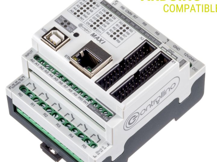
Project description
CONTROLLINO is an amazingly simple yet extremely powerful industrial PLC based on the Arduino Open Source Software Technology. Ideal for any building or industrial automation applications based on sensor inputs.

This incredible Arduino-PLC device currently offers 3 sizes: MINI, MAXI (Standard & Automation) and MEGA. All of them support a multitude of analog and digital inputs and outputs. For more information and a list of features for the CONTROLLINO, check out their website.
Connecting your Controllino
With your device in hand and this guide to assist you, in no time you can have your own CONTROLLINO driven Ubidots powered IoT Application for building automation or industrial processing.
Requirements
Step-by-Step
Setting up the Arduino IDE
Setting up the Controllino
Sending (POST) Data to Ubidots
Receiving (GET) Data from Ubidots
Summary
1. Setting up the Arduino IDE
1. To be able to work with the Controllino devices in the Arduino IDE, you will need to install the Controllino board using the preconfigured Arduino Board Manager. If you are not familiar with adding a board with the Arduino IDE, refer to this article for additional guidance.

2. With the Controllino board installed, next, select the Controllino device you are working with. In the case, we are workign with a "CONTROLLINO MAXI". To select your board from the Arduino IDE, select Tools –> Board "CONTROLLINO" and a MINI, MAXI, MAXI Automation, or MEGA board.

3. Download and install the following libraries:
Ubidots Ethernet library
Controllino Library
For a detailed explanation of how to install libraries using the Arduino IDE, refer to this guide.
IMPORTANT NOTE: Make sure to install the latest versions of these libraries.
4. With both libraries installed, close and restart the Arduino IDE.
2. Setting up the CONTROLLINO
1. To begin, take the CONTROLLINO device and connect it to a 12/24 power supply.
2. Once the device is properly powered, connect the CONTROLLINO to your computer using a USB and to the internet via an ethernet cable into an available router or internet port.
3. To verify the connection and check the IP address assigned to the device, go to the Arduino IDE and open the following example from Arduino > Examples > Ethernet > DhcpAddressPrinter. To verify that everything is ok with the example, press the Check Mark icon in the top-left corner of our Arduino IDE to Verify the code.

Next, your have to upload the code into your CONTROLLINO. To do this, choose the right-arrow icon beside the check mark icon to Upload the code.

To visualize the IP address assigned to the device, open the Serial Monitor of the Arduino IDE using the "magnifying glass" icon found in the top-right corner of your IDE display.

You will see the message below from the Serial Monitor providing the IP address the established connection with the internet.

If you are not able to see anIP address, verify if the device is properly connected and has powered. Also verify the Ethernet connection.
Now that you've verify that your device is properly connected, it is time to start sending data to Ubidots.
3. Sending (POST) Data to Ubidots
With the following sample code you will be able to post the ANALOG readings taken from Controllino MAXI device analog port A0.
1. To post your first value in Ubidots, open the Arduino IDE and paste the sample code below. Once you have pasted the code, you will need to assign your unique Ubidots TOKEN and the MAC Address of the Controllino device.
#include <Controllino.h>
#include <Ethernet.h>
#include <SPI.h>
#include <UbidotsEthernet.h>

#define TOKEN "Assign_your_Ubidots_token"  // Put here your Ubidots TOKEN
#define DEVICE_LABEL "controllino"  // Put here your Ubidots variable ID
#define VARIABLE_LABEL "sensor" // Put here your Ubidots variable label to POST data


// Enter a MAC address for your controller below.
// Newer Ethernet shields have a MAC address printed on a sticker on the shield
byte mac[] = { 0xDE, 0xAD, 0xBE, 0xEF, 0xFE, 0xED };
// Set the static IP address to use if the DHCP fails to assign
IPAddress ip(10, 42, 0, 121);

Ubidots client(TOKEN);

void setup(){

    pinMode(CONTROLLINO_A0, INPUT);

    Serial.begin(9600);
    // start the Ethernet connection:
    if (Ethernet.begin(mac) == 0) {
      Serial.println("Failed to configure Ethernet using DHCP");
      // try to congifure using IP address instead of DHCP:
      Ethernet.begin(mac, ip);
    }
    // give the Ethernet shield a second to initialize:
    delay(1000);
    client.setDeviceLabel(DEVICE_LABEL);
}

void loop(){
    /* Reading the sensor */
    float value = analogRead(CONTROLLINO_A0);
    /* Posting the variables to Ubidots*/
    client.add(VARIABLE_LABEL, value);
    client.sendAll();
}
2. Verify your code within the Arduino IDE. To do this, in the top left corner of our Arduino IDE you will see the "Check Mark" icon; press it to verify your code.
3. Upload the code into your Controllino device. To do this, choose the "right-arrow" icon beside the "check mark" icon.
4. To verify the connectivity of the device and the data sent, open the serial monitor by selecting the "magnifying glass" icon in the top right corner of the Arduino IDE to see the connectivity logs.
5. Confirm your data in Ubidots. In your Ubidots account, you now should see the posted data located the device called "controllino".

4. Receiving (GET) Data from Ubidots
With the following sample code you will be able to get a value from Ubidots to start controlling any asset you desire with your Controllino hardware.
1. To start getting values from Ubidots, open the Arduino IDE and paste the sample code below. Once you have pasted the code, be sure to assign the following parameters:
Device Label of the device containing the variable you want to GET.
Variable Label of the variable you want to GET.

#include <Controllino.h>
#include <Ethernet.h>
#include <SPI.h>
#include <UbidotsEthernet.h>

#define TOKEN  "Assign_your_Ubidots_token"  // Put here your Ubidots TOKEN
#define DEVICE_LABEL  "device_label_here"  // Put here your Ubidots variable ID
#define VARIABLE_LABEL  "variable_label_here"  // Put here your Ubidots  variable label to GET data
                                                          // This variable have to be created before in Ubidots
// Enter a MAC address for your controller below.
// Newer Ethernet shields have a MAC address printed on a sticker on the shield
byte mac[] = { 0xDE, 0xAD, 0xBE, 0xEF, 0xFE, 0xED };
// Set the static IP address to use if the DHCP fails to assign
IPAddress ip(10, 42, 0, 121);

Ubidots client(TOKEN);

void setup(){

    pinMode(CONTROLLINO_R0, OUTPUT);

    Serial.begin(9600);
    // start the Ethernet connection:
    if (Ethernet.begin(mac) == 0) {
      Serial.println("Failed to configure Ethernet using DHCP");
      // try to congifure using IP address instead of DHCP:
      Ethernet.begin(mac, ip);
    }
    // give the Ethernet shield a second to initialize:
    delay(1000);
}
void loop(){
    /* Getting the values from Ubidots */
    float control_status =  client.getValue(DEVICE_LABEL,VARIABLE_LABEL);
    /* Write a the value received from Ubidots (HIGH or LOW) to the Digital Pin*/
    digitalWrite(CONTROLLINO_R0, control_status);
}
2. Verify & Upload the code into the board following the same steps provided in the POST step above.
3. To verify the connectivity of the device and that the data is being received, open the serial monitor by selecting the "magnifying glass" icon in the top right corner of the Arduino IDE to see the connectivity logs.
4. At this point, you should be able to control any asset connected to the pin "CONTROLLINO_R0"
4.1. In order to control a variable, you have to create a control widget. Go to the Dashboard section, and press the "+" icon from the top right of the page to add the Widget.

4.2. To create the control widget click Control > Switch > controllino > {Your Variable} > finish.

Once your widget is created you should see something similar to the below widget on your dashboard:

Now you are able to control your CONTROLLINO from Ubidots!
5. Summary
In only a few minutes you've built an industrial IoT application using the robust and versatile Controllino, letting you send data and control assets.
Reference to the Ubidots Help Center for any doubts, and as always, don't forget the Ubidots support team is here to help you develop and deploy Ubidots powered Apps.
Happy Hacking! :)
Other readers have also found useful...
