12 Arctic tanks, four water conditions. M-Duino 42+ PLCs keep each on target.
12 Arctic tanks, four water conditions. M-Duino 42+ PLCs keep each on target.
0
Components
Hardware components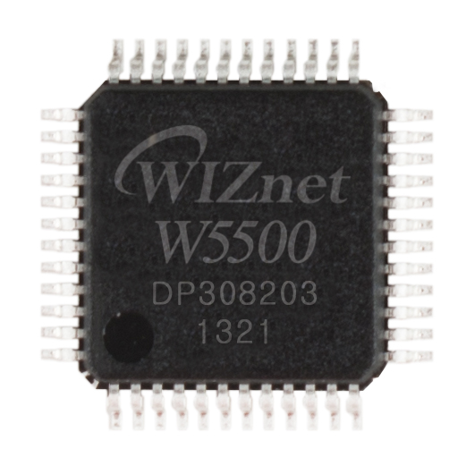
WIZnet - W5500
x 1


Arduino - Arduino Mega 2560
x 1
Project description
1. 프로젝트 개요 및 동작 방식
FACE-IT(The Future of Arctic Coastal Ecosystems)**은 노르웨이 스발바르 제도의 뉘올레순(Ny-Ålesund)에서 산업용 PLC를 활용해 해수 환경을 제어하는 기후변화 연구 프로젝트입니다. 북극 지역의 해수 온도 상승, 염도 감소, 탁도 변화가 연안 생태계에 미치는 영향을 조사하는 것이 목적입니다.
연구진은 자연 해양 환경을 모사하는 12개의 야외 메조코즘(Mesocosm) 수조를 설치했습니다. 메조코즘은 자연 생태계를 축소하여 특정 환경 조건을 제어할 수 있도록 만든 실험 시설입니다.
12개 수조 중 3개는 현재의 자연환경을 유지하는 대조군으로 사용하며, 나머지 9개는 2100년의 기후변화 시나리오를 재현합니다.
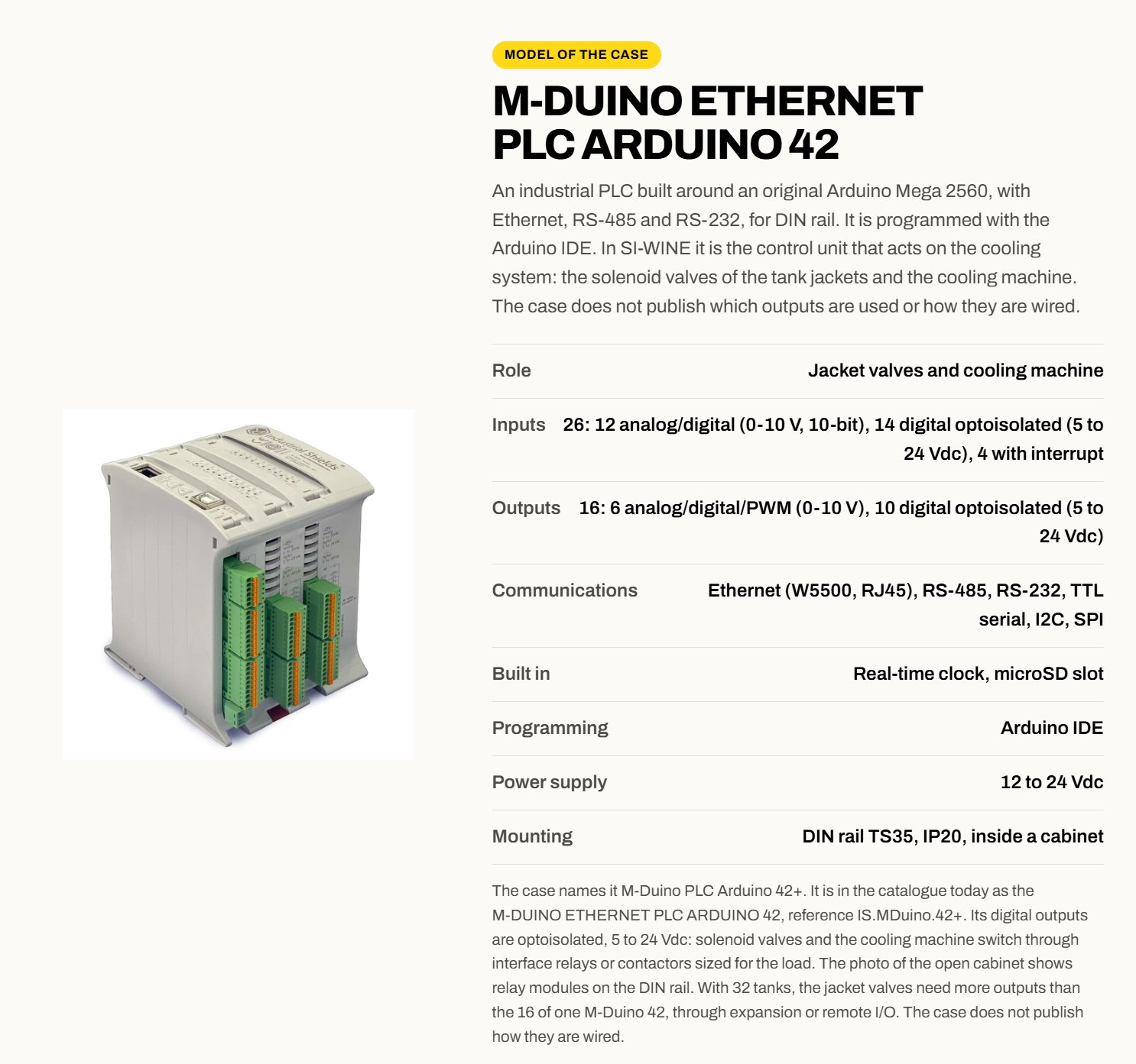
이 시스템에는 Industrial Shields의 M-Duino 42+ PLC 4대가 사용되며, 각 PLC가 3개의 메조코즘을 제어합니다. PLC는 RS-485를 통해 수온, 염도, 탁도 센서의 데이터를 수집하고 아날로그 출력으로 밸브를 조절하여 수조의 환경 조건을 유지합니다.
M-Duino에 내장된 WIZnet W5500 이더넷 컨트롤러는 RJ45 이더넷 연결을 제공합니다. 중앙 제어 컴퓨터에서는 C# 애플리케이션을 실행하며, PLC와 WebSocket 프로토콜로 데이터를 주고받고 제어 명령을 전달합니다.
이미지 출처 : https://www.industrialshields.com/success-story-wine-fermentation-control-sira
① 북극 메조코즘 실험 시설 (Arctic Mesocosm Installation)
이미지 출처: Industrial Shields / © Cale Miller
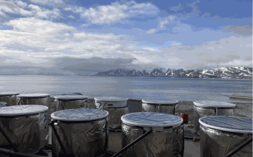
실험 시설은 스발바르 제도 뉘올레순의 피오르 해안에 설치된 12개의 단열 메조코즘 수조로 구성되어 있습니다.
각 수조에는 해수가 담겨 있으며, 서로 독립적인 환경에서 북극 해양 생태계의 변화를 연구할 수 있도록 설계되었습니다.
12개 수조는 3개씩 4개 그룹으로 나뉘며, 각 그룹에는 서로 다른 환경 조건이 적용됩니다. 이를 통해 연구진은 현재의 자연환경과 미래 기후변화 조건에서 발생하는 생태계 변화를 비교할 수 있습니다.
② 메조코즘 수조 내부 (Inside an Arctic Mesocosm)
이미지 출처: Industrial Shields / © Anaïs Lebrun
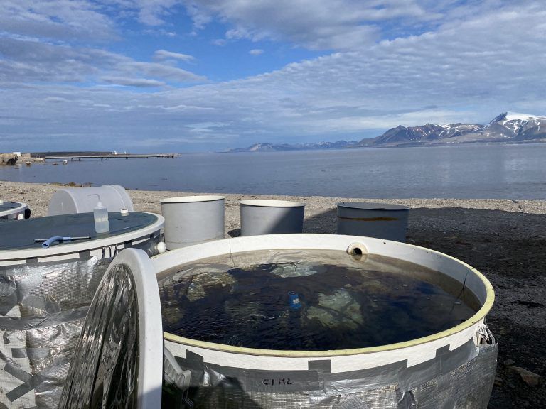
메조코즘 내부에는 주변 북극 해양 환경에서 채취한 해수가 담겨 있습니다.
수조에 설치된 센서는 수온(Temperature), 염도(Salinity), 탁도(Turbidity)를 측정하며, 제어 시스템은 측정값과 실험 목표값을 비교하여 환경 조건을 관리합니다.
각 실험 그룹의 환경을 일정하게 유지하는 것은 연구 결과의 신뢰성을 확보하는 데 중요합니다. 제어되지 않은 환경 변화가 발생하면 실험 그룹 간 비교 결과에 영향을 줄 수 있기 때문입니다.
③ 메조코즘 및 급수 시스템 (Mesocosms and Water Distribution System)
이미지 출처: Industrial Shields / © Frédéric Gazeau
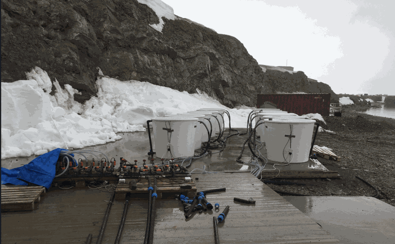
각 메조코즘은 온도와 염도가 다른 물을 공급할 수 있는 급수 시스템에 연결되어 있습니다.
수조마다 두 개의 독립적인 제어 밸브가 설치되어 있습니다.
온도 조절 밸브: 공급되는 물의 흐름을 조절하여 수조의 온도를 제어합니다.
담수 공급 밸브: 담수 유입량을 조절하여 수조의 염도를 낮춥니다.
M-Duino PLC는 센서에서 수집한 측정값을 바탕으로 각 밸브를 제어합니다. 이를 통해 12개 수조가 서로 다른 기후변화 실험 조건을 유지할 수 있습니다.
④ 급수 제어 밸브 매니폴드 (Water Control Valve Manifold)
이미지 출처: Industrial Shields / © Frédéric Gazeau
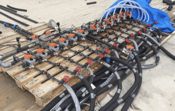
밸브 매니폴드는 각 메조코즘에 공급되는 물의 흐름을 조절하는 장치입니다.
각 수조에는 다음과 같은 두 종류의 밸브가 사용됩니다.
3방향 온도 제어 밸브(3-way Valve): 공급되는 물을 조절하여 수조 온도를 유지합니다.
2방향 담수 제어 밸브(2-way Valve): 담수 공급량을 조절하여 염도를 낮춥니다.
두 밸브 모두 PLC의 아날로그 출력 신호로 제어됩니다.
각 PLC는 3개 수조를 담당하므로 총 6개의 아날로그 밸브 제어 신호가 필요합니다. 이는 M-Duino 42+가 제공하는 6개의 아날로그 출력 채널과 일치합니다.
다만 실제 밸브의 제어 전압 범위, 제어 파라미터 및 조절 알고리즘은 공개되지 않았습니다.
⑤ 산업용 PLC 제어 캐비닛 (Industrial PLC Control Cabinet)
원본 이미지: Industrial Shields 제어 캐비닛
이미지 출처: Industrial Shields / © Frédéric Gazeau
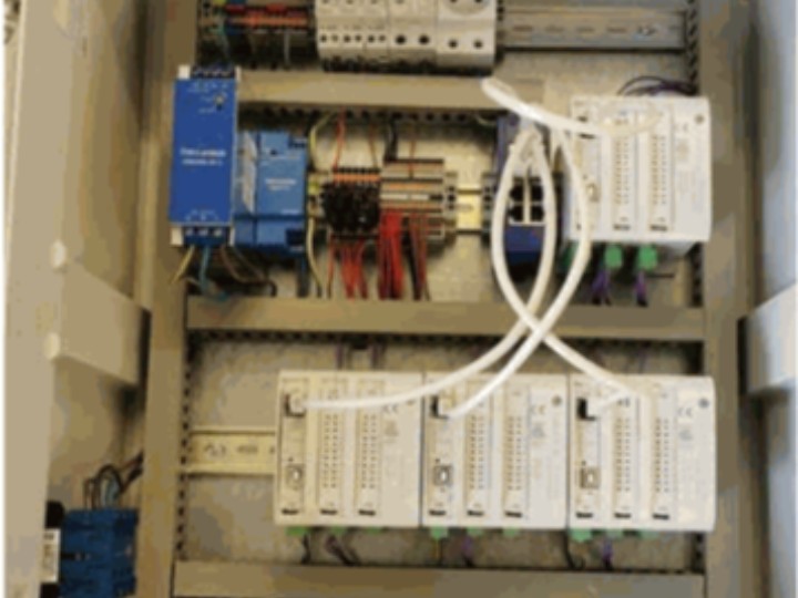
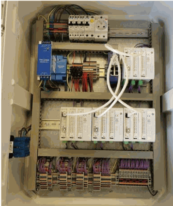
제어 캐비닛에는 Industrial Shields PLC와 현장 배선 단자, 전원 분배 장치 및 통신 연결부가 설치되어 있습니다.
시스템에는 M-Duino PLC 4대가 사용되며, 각 PLC는 다음 세 가지 기능을 수행합니다.
센서 데이터 수집: RS-485 통신으로 수온, 염도, 탁도 센서의 측정값을 읽습니다.
밸브 제어: 3개 수조에 연결된 총 6개의 밸브를 아날로그 출력으로 조절합니다.
네트워크 통신: 이더넷을 통해 중앙 제어 컴퓨터와 측정 데이터 및 제어 명령을 교환합니다.
PLC 중 1대는 마스터(Master) 역할을 수행하며, 실험 데이터를 microSD 카드에 기록합니다.
중앙 제어 컴퓨터에서는 C#으로 작성된 애플리케이션이 실행되며, PLC의 RJ45 이더넷 포트를 통해 WebSocket 통신을 수행합니다.
⑥ 기후변화 실험 시나리오 (Climate Change Experiment Design)
이미지 출처: Industrial Shields / © Steeve Comeau
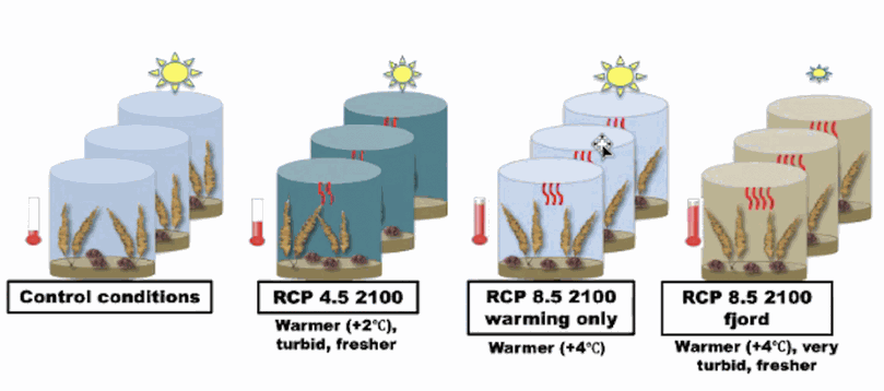
연구진은 2100년의 북극 해양 환경을 모사하기 위해 12개 수조를 4개 실험 그룹으로 구분했습니다.
| 실험 그룹 | 수조 수 | 실험 환경 |
|---|---|---|
| 대조군(Control) | 3개 | 현재의 수온, 염도 및 탁도 유지 |
| RCP 4.5 — 2100년 | 3개 | 수온 2°C 상승, 염도 감소, 탁도 증가 |
| RCP 8.5 — 2100년 (수온 상승) | 3개 | 수온 4°C 상승, 나머지 환경 조건 유지 |
| RCP 8.5 — 2100년 (피오르 환경) | 3개 | 수온 4°C 상승, 탁도 크게 증가, 염도 감소 |
RCP(Representative Concentration Pathway)는 기후변화 연구에서 사용하는 온실가스 농도 경로 시나리오입니다.
각 그룹에 3개 수조를 배치하여 동일한 실험 조건을 반복 적용하고, 현재 환경과 미래 시나리오 사이의 차이를 비교할 수 있도록 구성했습니다.
PLC는 수온과 담수 공급량을 조절하며, 센서는 수온, 염도, 탁도를 측정합니다. 다만 탁도를 어떤 장치로 직접 조절하는지는 원본 사례에 명시되어 있지 않습니다.
신호 및 데이터 흐름 (Signals and Data Flow)
| 신호 | 연결 구간 | 통신 및 제어 방식 | 목적 및 기능 |
|---|---|---|---|
| 수온 | 수온 센서 → M-Duino PLC | RS-485 | 각 수조의 수온을 측정하고 온도 제어에 활용합니다. |
| 염도 | 염도 센서 → M-Duino PLC | RS-485 | 염도를 측정하여 담수 공급량을 조절하는 데 활용합니다. |
| 탁도 | 탁도 센서 → M-Duino PLC | RS-485 | 기후변화 시나리오에 따른 수질 탁도를 모니터링합니다. |
| 온도 제어 밸브 | M-Duino PLC → 3방향 밸브 | 아날로그 출력 | 물의 공급 상태를 조절하여 수조 온도를 제어합니다. |
| 담수 제어 밸브 | M-Duino PLC → 2방향 밸브 | 아날로그 출력 | 담수 공급량을 조절하여 염도를 낮춥니다. |
| 데이터 기록 | 마스터 PLC → microSD 카드 | 로컬 저장 | 실험 측정 데이터를 로컬 저장 장치에 기록합니다. |
| 중앙 제어 통신 | M-Duino PLC ↔ 중앙 컴퓨터 | Ethernet / WebSocket | 측정 데이터를 전송하고 제어 명령을 수신합니다. |
| 모니터링 인터페이스 | 중앙 제어 컴퓨터 | C# 애플리케이션 | 실험 데이터를 표시하고 전체 시스템을 중앙에서 관리합니다. |
센서 모델명, RS-485 통신 프로토콜, WebSocket 메시지 형식 및 데이터 기록 주기는 공개되지 않았습니다.
2. WIZnet W5500의 역할과 기술적 의미
왜 W5500을 사용했을까요?
M-Duino 42+는 8비트 ATmega2560 마이크로컨트롤러를 사용하는 Arduino Mega 2560 기반 산업용 PLC입니다.
ATmega2560은 SRAM이 8KB이므로 네트워크 통신에 사용할 수 있는 메모리와 연산 자원이 제한적입니다.
WIZnet W5500은 하드웨어 TCP/IP 스택을 내장하고 있어, MCU에서 TCP/IP 프로토콜 전체를 소프트웨어로 처리하지 않고도 이더넷 통신 기능을 구현할 수 있습니다.
주요 기술적 특징은 다음과 같습니다.
하드웨어 TCP/IP 처리: MCU의 네트워크 프로토콜 처리 부담을 줄여줍니다.
32KB 내부 송수신 버퍼: 네트워크 데이터 전송과 수신을 위한 전용 메모리를 제공합니다.
8개 하드웨어 소켓: 여러 TCP/UDP 연결을 지원합니다.
SPI 인터페이스: ATmega2560과 연결됩니다.
10/100Mbps 이더넷: PLC의 RJ45 포트를 통해 유선 네트워크 연결을 제공합니다.
이번 프로젝트에서 특히 중요한 부분은 PLC와 중앙 제어 컴퓨터가 WebSocket을 이용하여 실험 데이터와 제어 명령을 교환한다는 점입니다.
WebSocket은 TCP 연결을 기반으로 양방향 통신을 제공하는 프로토콜입니다.
W5500은 하위 TCP/IP 통신을 처리하고, WebSocket 메시지의 구성과 처리는 PLC 펌웨어에서 구현해야 합니다.
실제 프로젝트에서 사용한 WebSocket 펌웨어 코드는 공개되지 않았습니다.
왜 이더넷이 필요할까요?
메조코즘은 북극의 야외 연구 환경에 설치되어 있으며, PLC와 중앙 컴퓨터 사이에서 안정적으로 데이터를 교환하는 것이 중요합니다.
이번 프로젝트는 현장 센서 통신과 중앙 제어 통신을 구분하는 구조를 사용합니다.
RS-485: 수온, 염도 및 탁도 센서를 PLC에 연결합니다.
아날로그 출력: 온도 제어 밸브와 담수 공급 밸브를 조절합니다.
W5500 이더넷: PLC와 중앙 제어 컴퓨터를 연결합니다.
이러한 구조에서는 각 PLC가 담당 수조의 센서 측정과 밸브 제어를 수행하면서, 중앙 컴퓨터는 전체 실험 상태를 모니터링하고 제어 명령을 전달할 수 있습니다.
고정된 제어 장비 사이에서는 Wi-Fi보다 유선 이더넷이 무선 신호 범위와 전파 간섭에 영향을 받지 않는다는 장점이 있습니다.
다만 유선 이더넷을 사용한다고 해서 통신이 중단되지 않는 것은 아닙니다. 실제 시스템에서는 통신 장애 발생 시에도 안전한 제어 상태를 유지할 수 있도록 설계해야 합니다.
제품 및 시장 관점
이번 사례는 W5500을 내장한 상용 산업용 PLC가 실제 환경 연구 장비의 제어 시스템에 사용되었다는 점에서 의미가 있습니다.
일반적인 공장 자동화와 비교하면 특수한 연구 분야이지만, 센서 데이터 수집과 아날로그 제어, 중앙 모니터링을 결합한 시스템 구조는 다른 산업 분야에도 적용할 수 있습니다.
| 타깃 고객 | 사업 기회 |
|---|---|
| 산업용 PLC 제조사 | MCU 기반 산업용 제어기에 W5500 이더넷 인터페이스 적용 |
| 과학 연구 장비 제조사 | 환경 실험용 모니터링 및 제어 장비의 이더넷 연결 |
| 연구 시스템 통합업체 | 여러 실험 수조 및 챔버를 연결하는 분산 제어 시스템 구축 |
| 환경 모니터링 장비 제조사 | 수질 측정 및 자동 시료 채취 장비의 네트워크 기능 구현 |
WIZnet의 직접적인 사업 기회는 산업용 제어기와 과학 연구 장비를 개발하는 제조사를 대상으로 한 OEM 설계 채택이라고 볼 수 있습니다.
FACE-IT은 W5500 탑재 PLC의 실제 적용 사례이지만, 공개된 설치 구성 이외의 PLC 구매 수량이나 W5500 판매 물량, 매출 성과는 확인되지 않았습니다.
3. 구현 및 기술 참고사항
M-Duino 42+와 W5500 연결
Industrial Shields의 M-Duino 42+ 사용자 설명서 10.6절에는 다음과 같이 명시되어 있습니다.
M-Duino Ethernet port controller is based on w5500 IC
W5500은 Arduino Mega 2560과 SPI 인터페이스로 연결됩니다.
| SPI 신호 | Arduino Mega 핀 |
|---|---|
| MISO | D50 |
| MOSI | D51 |
| SCK | D52 |
| Chip Select | D10 |
M-Duino에는 W5500과 RJ45 포트가 내장되어 있으므로 별도의 이더넷 확장 보드를 추가할 필요가 없습니다.
PLC 제어 아키텍처
시스템은 총 4대의 PLC로 구성되며, 각 PLC가 3개의 메조코즘을 담당합니다.
M-Duino 42+의 주요 하드웨어 자원과 프로젝트에서의 역할은 다음과 같습니다.
| 하드웨어 자원 | 사양 | 프로젝트 내 역할 |
|---|---|---|
| 메인 MCU | ATmega2560, 16MHz | 센서 데이터 수집 및 밸브 제어 |
| 아날로그 출력 | 6채널, 0–10V 출력 지원 | 3개 수조의 밸브 6개 제어 |
| RS-485 | 내장 시리얼 인터페이스 | 수온, 염도, 탁도 센서 통신 |
| W5500 이더넷 | 10/100Mbps, RJ45 | 중앙 컴퓨터와 WebSocket 통신 |
| microSD | 내장 카드 슬롯 | 실험 데이터 로컬 저장 |
| 전원 | 12–24V DC | 산업용 제어기 전원 공급 |
마스터 PLC는 실험 데이터를 microSD 카드에 기록하며, 중앙 C# 애플리케이션은 이더넷을 통해 실험 상태를 모니터링하고 제어합니다.
구현 시 확인할 점: 원본에서는 실제 펌웨어, 밸브 제어 알고리즘, 센서 통신 프로토콜 및 WebSocket 메시지 형식을 공개하지 않았습니다. 따라서 전체 소스 코드보다는 하드웨어 구성과 통신 아키텍처를 중심으로 확인할 수 있는 사례입니다.
4. 실제 적용 시 고려사항
아날로그 출력 채널: 각 PLC가 3개 수조의 밸브 6개를 제어하므로 모든 아날로그 출력 채널을 사용합니다. 장치를 추가하려면 출력 채널 수와 액추에이터의 제어 전압 범위를 확인해야 합니다.
RS-485 통신: 센서 연결 시 종단 저항, 케이블 차폐 및 장치 주소 설정을 고려해야 합니다. 실제 프로젝트에서 사용한 센서 통신 프로토콜은 공개되지 않았습니다.
이더넷 통신 안정성: 북극 야외 설치 환경에서는 습기, 결로 및 기계적 충격으로부터 RJ45 커넥터와 네트워크 케이블을 보호해야 합니다.
TCP 연결 관리: W5500은 8개 하드웨어 소켓을 지원합니다. 지속적인 WebSocket 연결을 사용하는 경우 연결 상태 확인과 재접속 처리가 필요합니다.
로컬 제어 유지: 중앙 컴퓨터와의 통신이 중단되더라도 필수적인 센서 수집과 밸브 제어가 유지되도록 설계하는 것이 중요합니다.
microSD 데이터 기록: W5500과 microSD는 MCU의 SPI 자원을 공유합니다. 각 장치의 Chip Select 신호와 접근 시점을 적절하게 관리해야 합니다. M-Duino 42+에서 W5500은 D10, microSD는 D53을 사용합니다.
5. FAQ
Q1. 북극 환경 제어 시스템에서 W5500을 사용하는 이유는 무엇인가요?
W5500은 하드웨어 TCP/IP 스택과 전용 네트워크 버퍼를 제공하여 ATmega2560 기반 PLC의 메모리 및 네트워크 처리 부담을 줄여줍니다. 이번 프로젝트에서는 중앙 제어 컴퓨터와 WebSocket 통신을 수행하는 PLC의 이더넷 인터페이스로 활용됩니다.
Q2. W5500은 M-Duino 42+에 어떻게 연결되나요?
W5500은 SPI 인터페이스를 통해 ATmega2560과 연결되며 MISO(D50), MOSI(D51), SCK(D52), CS(D10)를 사용합니다. 이더넷 하드웨어는 PLC에 내장되어 있으며 외부 네트워크는 RJ45 포트로 연결합니다.
Q3. 메조코즘 제어에서 W5500은 어떤 역할을 하나요?
W5500은 M-Duino PLC와 중앙 제어 컴퓨터 사이의 네트워크 연결을 담당합니다. WebSocket에서 사용하는 TCP 통신을 지원하여 측정 데이터와 제어 명령을 교환할 수 있도록 합니다. 수온과 염도를 직접 측정하거나 밸브를 구동하는 것은 아니며, 해당 기능은 RS-485 및 아날로그 출력을 통해 수행됩니다.
Q4. Arduino 개발자도 비슷한 W5500 기반 시스템을 구현할 수 있나요?
Arduino, SPI, 이더넷 통신, RS-485 및 아날로그 출력에 대한 경험이 있다면 소규모 실험 시스템을 구현할 수 있습니다. 실제 메조코즘 시설을 구축하려면 산업용 밸브 제어, 센서 보정, 전기적 보호 및 환경 계측에 대한 추가적인 지식이 필요합니다.
Q5. Wi-Fi나 소프트웨어 TCP/IP 스택 대신 W5500을 사용하는 이유는 무엇인가요?
고정된 PLC와 중앙 컴퓨터 사이에서는 유선 이더넷을 사용하면 무선 신호 범위나 전파 간섭에 대한 의존도를 줄일 수 있습니다. 또한 LwIP와 같은 소프트웨어 TCP/IP 스택과 달리 W5500은 TCP/IP 처리와 소켓 버퍼를 하드웨어에서 제공하므로 SRAM이 제한적인 ATmega2560에 적합합니다. 다만 WebSocket 메시지 처리, 연결 장애 대응 및 복구 로직은 별도로 구현해야 합니다.
1. Project Overview and How It Works
FACE-IT (The Future of Arctic Coastal Ecosystems) is a climate change research project that uses industrial PLCs to control seawater conditions in Ny-Ålesund, Svalbard, Norway. The project aims to investigate how rising seawater temperatures, decreasing salinity, and changes in turbidity affect Arctic coastal ecosystems.
Researchers installed 12 outdoor mesocosm tanks to simulate natural marine environments. A mesocosm is an experimental facility designed to reproduce a smaller-scale natural ecosystem under controlled environmental conditions.
Three of the 12 tanks serve as control groups, maintaining present-day environmental conditions, while the remaining nine simulate climate change scenarios projected for 2100.
The system uses four Industrial Shields M-Duino 42+ PLCs, with each PLC controlling three mesocosms. The PLCs collect water temperature, salinity, and turbidity measurements through RS-485 and regulate the tanks' environmental conditions by controlling valves through analog outputs.
The WIZnet W5500 Ethernet controller integrated into the M-Duino provides RJ45 Ethernet connectivity. A C# application running on the central control computer exchanges data and sends control commands to the PLCs using the WebSocket protocol.
Project Overview and How It Works
Image Source: https://www.industrialshields.com/success-story-wine-fermentation-control-sira
① Arctic Mesocosm Installation
Original Image: Arctic Mesocosm Tanks
Image Source: Industrial Shields / © Cale Miller
The experimental facility consists of 12 insulated mesocosm tanks installed along the shore of a fjord in Ny-Ålesund, Svalbard.
Each tank contains seawater and is designed to provide an independent environment for studying changes in Arctic marine ecosystems.
The 12 tanks are divided into four groups of three, with different environmental conditions applied to each group. This arrangement allows researchers to compare ecological changes under present-day conditions with those projected under future climate change scenarios.
② Inside an Arctic Mesocosm
An open mesocosm tank full of seawater on the shore in Svalbard, with the fjord and mountains behind
Original Image: Open Mesocosm Tank
Image Source: Industrial Shields / © Anaïs Lebrun
Each mesocosm contains seawater collected from the surrounding Arctic marine environment.
Sensors installed in the tanks measure water temperature, salinity, and turbidity. The control system compares these measurements with the target experimental values to maintain the required environmental conditions.
Maintaining consistent conditions within each experimental group is essential for ensuring reliable research results. Uncontrolled environmental changes could affect comparisons between the experimental groups.
③ Mesocosms and Water Distribution System
Original Image: Mesocosm Installation
Image Source: Industrial Shields / © Frédéric Gazeau
Each mesocosm is connected to a water distribution system capable of supplying water at different temperatures and salinity levels.
Two independent control valves are installed for each tank.
Temperature Control Valve: Regulates the flow of supplied water to control the tank's temperature.
Freshwater Supply Valve: Adjusts the amount of freshwater entering the tank to reduce salinity.
The M-Duino PLC controls these valves based on the measurements collected from the sensors. This enables the 12 tanks to maintain different environmental conditions required for the climate change experiments.
④ Water Control Valve Manifold
Valve manifold with orange valve actuators, red manual valves, and black hoses on a wooden pallet
Original Image: Water Control Valves
Image Source: Industrial Shields / © Frédéric Gazeau
The valve manifold controls the flow of water supplied to each mesocosm.
Each tank uses two types of valves.
3-Way Temperature Control Valve: Regulates the supplied water to maintain the tank's temperature.
2-Way Freshwater Control Valve: Controls freshwater flow to reduce salinity.
Both valves are controlled through analog output signals from the PLC.
Since each PLC manages three tanks, a total of six analog valve control signals is required. This matches the six analog output channels available on the M-Duino 42+.
However, the actual valve control voltage ranges, control parameters, and regulation algorithms have not been disclosed.
⑤ Industrial PLC Control Cabinet
Control cabinet with Industrial Shields PLCs on DIN rails, network cables, and terminal blocks
Original Image: Industrial Shields Control Cabinet
Image Source: Industrial Shields / © Frédéric Gazeau
The control cabinet contains Industrial Shields PLCs, field wiring terminals, power distribution components, and communication connections.
The system uses four M-Duino PLCs, each performing three main functions.
Sensor Data Acquisition: Reads water temperature, salinity, and turbidity measurements through RS-485 communication.
Valve Control: Regulates six valves connected to three tanks using analog outputs.
Network Communication: Exchanges measurement data and control commands with the central control computer over Ethernet.
One of the PLCs operates as the master and records experimental data on a microSD card.
A C# application runs on the central control computer and communicates with the PLCs through their RJ45 Ethernet ports using WebSocket.
⑥ Climate Change Experiment Design
Original Image: FACE-IT Experiment Design
Image Source: Industrial Shields / © Steeve Comeau
To simulate Arctic marine conditions projected for 2100, the researchers divided the 12 tanks into four experimental groups.
| Experimental Group | Number of Tanks | Experimental Conditions |
|---|---|---|
| Control | 3 | Maintains present-day water temperature, salinity, and turbidity |
| RCP 4.5 — 2100 | 3 | Water temperature increased by 2°C, reduced salinity, and increased turbidity |
| RCP 8.5 — 2100 (Warming Only) | 3 | Water temperature increased by 4°C, with other environmental conditions maintained |
| RCP 8.5 — 2100 (Fjord Scenario) | 3 | Water temperature increased by 4°C, significantly increased turbidity, and reduced salinity |
RCP (Representative Concentration Pathway) refers to greenhouse gas concentration scenarios used in climate change research.
Each group contains three tanks to replicate the same experimental conditions, allowing researchers to compare present-day environmental conditions with projected future scenarios.
The PLCs regulate water temperature and freshwater supply, while the sensors measure temperature, salinity, and turbidity. However, the original case study does not specify which equipment is used to actively regulate turbidity.
Signals and Data Flow
| Signal | Connection | Communication or Control Method | Purpose and Function |
|---|---|---|---|
| Water Temperature | Temperature sensor → M-Duino PLC | RS-485 | Measures the water temperature in each tank for temperature regulation. |
| Salinity | Salinity sensor → M-Duino PLC | RS-485 | Measures salinity to determine freshwater supply adjustments. |
| Turbidity | Turbidity sensor → M-Duino PLC | RS-485 | Monitors water turbidity under different climate change scenarios. |
| Temperature Control Valve | M-Duino PLC → 3-way valve | Analog output | Regulates water supply to control tank temperature. |
| Freshwater Control Valve | M-Duino PLC → 2-way valve | Analog output | Adjusts freshwater supply to reduce salinity. |
| Data Logging | Master PLC → microSD card | Local storage | Records experimental measurements in local storage. |
| Central Control Communication | M-Duino PLC ↔ Central computer | Ethernet / WebSocket | Transmits measurement data and receives control commands. |
| Monitoring Interface | Central control computer | C# application | Displays experimental data and provides centralized system management. |
The sensor models, RS-485 communication protocol, WebSocket message format, and data logging interval have not been disclosed.
2. Role and Technical Significance of the WIZnet W5500
Why Is the W5500 Used?
The M-Duino 42+ is an Arduino Mega 2560-based industrial PLC equipped with an 8-bit ATmega2560 microcontroller.
The ATmega2560 has only 8 KB of SRAM, limiting the memory and processing resources available for network communication.
The WIZnet W5500 integrates a hardware TCP/IP stack, enabling Ethernet connectivity without requiring the MCU to process the entire TCP/IP protocol stack in software.
Its main technical features include:
Hardware TCP/IP Processing: Reduces the MCU's network protocol processing overhead.
32 KB Internal Transmit/Receive Buffer: Provides dedicated memory for network data transmission and reception.
8 Hardware Sockets: Supports multiple TCP/UDP connections.
SPI Interface: Connects the Ethernet controller to the ATmega2560.
10/100 Mbps Ethernet: Provides wired network connectivity through the PLC's RJ45 port.
An important aspect of this project is that the PLCs and the central control computer exchange experimental data and control commands using WebSocket.
WebSocket is a protocol that enables bidirectional communication over a TCP connection.
The W5500 handles the underlying TCP/IP communication, while WebSocket message construction and processing must be implemented in the PLC firmware.
The WebSocket firmware used in the actual project has not been publicly released.
Why Is Ethernet Necessary?
The mesocosms are installed in an outdoor Arctic research environment, where reliable data exchange between the PLCs and the central computer is important.
The project uses a system architecture that separates field-level sensor communication from central control communication.
RS-485: Connects water temperature, salinity, and turbidity sensors to the PLCs.
Analog Outputs: Control temperature regulation valves and freshwater supply valves.
W5500 Ethernet: Connects the PLCs to the central control computer.
With this architecture, each PLC acquires sensor measurements and controls valves for its assigned tanks, while the central computer monitors the overall experimental conditions and sends control commands.
For fixed control equipment, wired Ethernet offers the advantage of avoiding dependence on wireless signal coverage and radio interference compared with Wi-Fi.
However, wired Ethernet does not eliminate the possibility of communication interruptions. The system must be designed to maintain a safe operating state even when network communication fails.
Product and Market Perspective
This case is significant because commercial industrial PLCs equipped with the W5500 are being used in a real environmental research control system.
Although this is a specialized research application compared with conventional factory automation, the architecture combining sensor data acquisition, analog control, and centralized monitoring can also be applied to other industrial sectors.
| Target Customers | Business Opportunities |
|---|---|
| Industrial PLC Manufacturers | Integration of W5500 Ethernet interfaces into MCU-based industrial controllers |
| Scientific Research Equipment Manufacturers | Ethernet connectivity for environmental experiment monitoring and control equipment |
| Research System Integrators | Development of distributed control systems connecting multiple experimental tanks and chambers |
| Environmental Monitoring Equipment Manufacturers | Network functionality for water quality monitoring and automated sampling equipment |
WIZnet's direct business opportunity lies in achieving OEM design adoption among manufacturers developing industrial controllers and scientific research equipment.
FACE-IT demonstrates a real-world application of W5500-equipped PLCs. However, PLC purchasing quantities beyond the published installation, W5500 sales volumes, and revenue results have not been disclosed.
3. Implementation and Technical Notes
Connecting the M-Duino 42+ and W5500
Section 10.6 of the Industrial Shields M-Duino 42+ User Guide states:
M-Duino Ethernet port controller is based on w5500 IC
The W5500 communicates with the Arduino Mega 2560 through the SPI interface.
| SPI Signal | Arduino Mega Pin |
|---|---|
| MISO | D50 |
| MOSI | D51 |
| SCK | D52 |
| Chip Select | D10 |
Since the W5500 and RJ45 port are integrated into the M-Duino, no additional Ethernet expansion board is required.
PLC Control Architecture
The system consists of four PLCs, each responsible for controlling three mesocosms.
The following table summarizes the main hardware resources of the M-Duino 42+ and their roles in the project.
| Hardware Resource | Specification | Role in the Project |
|---|---|---|
| Main MCU | ATmega2560, 16 MHz | Sensor data acquisition and valve control |
| Analog Outputs | 6 channels, 0–10 V output support | Controls six valves across three tanks |
| RS-485 | Integrated serial interface | Communication with water temperature, salinity, and turbidity sensors |
| W5500 Ethernet | 10/100 Mbps, RJ45 | WebSocket communication with the central computer |
| microSD | Integrated card slot | Local storage of experimental data |
| Power Supply | 12–24 V DC | Power supply for the industrial controller |
The master PLC records experimental data on a microSD card, while the central C# application monitors and controls the experiment over Ethernet.
Implementation Considerations: The original project does not publish its actual firmware, valve control algorithms, sensor communication protocol, or WebSocket message format. Therefore, the available documentation primarily supports an analysis of the hardware configuration and communication architecture rather than a complete source-code implementation.
4. Practical Considerations
Analog Output Channels: Each PLC uses all six analog output channels to control six valves across three tanks. Adding more devices requires verification of the available output channels and the actuator control voltage ranges.
RS-485 Communication: Bus termination resistors, cable shielding, and device addressing should be considered when connecting sensors. The sensor communication protocol used in the actual project has not been disclosed.
Ethernet Reliability: In outdoor Arctic installations, RJ45 connectors and network cables must be protected against moisture, condensation, and mechanical stress.
TCP Connection Management: The W5500 supports eight hardware sockets. Persistent WebSocket connections require connection monitoring and reconnection handling.
Local Control Continuity: Essential sensor acquisition and valve control should remain operational even if communication with the central computer is interrupted.
microSD Data Logging: The W5500 and microSD share the MCU's SPI resources. Chip Select signals and device access timing must be managed appropriately. On the M-Duino 42+, the W5500 uses D10, while the microSD uses D53.
5. FAQ
Q1. Why is the W5500 used in an Arctic environmental control system?
The W5500 provides a hardware TCP/IP stack and dedicated network buffers, reducing the memory requirements and network processing overhead of the ATmega2560-based PLC. In this project, it serves as the PLC's Ethernet interface for WebSocket communication with the central control computer.
Q2. How is the W5500 connected to the M-Duino 42+?
The W5500 connects to the ATmega2560 through the SPI interface using MISO (D50), MOSI (D51), SCK (D52), and CS (D10). The Ethernet hardware is integrated into the PLC, and external network connections are established through the RJ45 port.
Q3. What role does the W5500 play in mesocosm control?
The W5500 provides network connectivity between the M-Duino PLCs and the central control computer. It supports the TCP communication used by WebSocket to exchange measurement data and control commands. It does not directly measure water temperature or salinity or drive the valves; those functions are handled through RS-485 and analog outputs.
Q4. Can Arduino developers build a similar W5500-based system?
Developers with experience in Arduino, SPI, Ethernet communication, RS-485, and analog outputs can build a small-scale experimental system. However, implementing a complete mesocosm facility requires additional knowledge of industrial valve control, sensor calibration, electrical protection, and environmental instrumentation.
Q5. Why use the W5500 instead of Wi-Fi or a software TCP/IP stack?
For communication between fixed PLCs and a central computer, wired Ethernet reduces dependence on wireless signal coverage and radio interference. Unlike software TCP/IP stacks such as LwIP, the W5500 provides hardware TCP/IP processing and socket buffers, making it suitable for the ATmega2560's limited SRAM. However, WebSocket message handling, connection failure management, and recovery logic must still be implemented separately.

