SUTS-1
SUTS-1
0
Components
Hardware components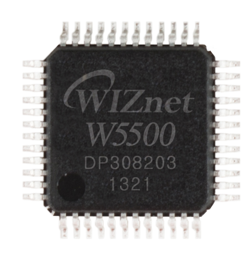
WIZnet - W5500
x 1

Espressif - ESP32
x 1
Project description
1. 프로젝트 개요 및 시스템 구성
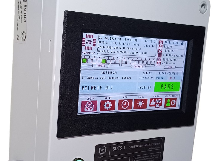
SUTS-1(Small Universal Test System)은 체코 HWPRO에서 개발한 ESP32-S3 기반 산업용 전자제품 검사 장비입니다. 생산라인에서 전자제품의 회로 연결 상태와 기능 정상 여부를 확인하기 위해 ICT(In-Circuit Test)와 FT(Functional Test)를 지원합니다.


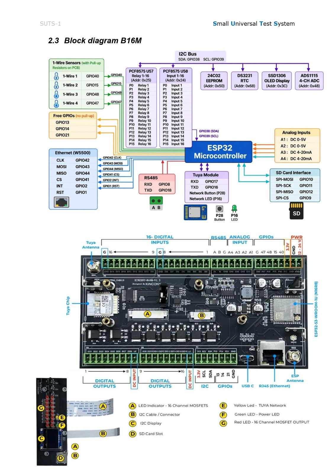
이 장비는 KinCony B16M 제어 보드를 기반으로 디지털·아날로그 입출력, 제품 식별, 검사 결과 판정 및 데이터 저장 기능을 통합했습니다. WIZnet W5500은 유선 Ethernet 통신을 담당하며, ESP32-S3와 SPI 인터페이스로 연결됩니다.
주요 하드웨어 구성
| 구성요소 | 역할 |
|---|---|
| ESP32-S3 / KinCony B16M | 검사 프로그램 실행 및 시스템 제어 |
| DB37 검사 어댑터 | 검사 대상 제품(DUT) 연결 및 검사 프로그램 식별 |
| 디지털 I/O 16입력·16출력 | 제품 상태 확인 및 제어 신호 출력 |
| 16비트 ADC 4채널 | 아날로그 신호 측정 |
| 릴레이 2개 | 검사 회로 전환 |
| 바코드·RFID 스캐너 | 작업자, 작업 지시 및 제품 일련번호 식별 |
| 7인치 터치스크린 | 검사 진행 상태와 결과 표시 |
| SD 카드 및 RTC | 검사 데이터와 시간 정보 저장 |
| WIZnet W5500 | 유선 Ethernet 인터페이스 |
| Tuya Wi-Fi 모듈 | 별도의 2.4GHz 무선 통신 인터페이스 |
검사 과정
작업자·제품 식별 → 어댑터 연결 → 검사 프로그램 선택 → 신호 측정 → PASS/NG 판정 → 결과 저장
SUTS-1은 DB37 검사 어댑터의 4비트 BCD 신호를 이용하여 최대 16종의 검사 어댑터를 구분할 수 있습니다. 어댑터가 연결되면 해당 검사 프로그램이 자동으로 선택되므로 작업자가 제품별 프로그램을 직접 지정할 필요가 없습니다.
검사 결과는 터치스크린에 표시되며, 이벤트와 측정 데이터는 SD 카드에 TXT 또는 CSV 형식으로 기록됩니다. 저장된 데이터는 USB-C 인터페이스를 통해 PC에서 추출할 수 있습니다.

바코드·RFID 스캐너는 어떤 역할을 하나요?
SUTS-1의 바코드 스캐너는 검사 대상 제품과 작업 정보를 식별하고 검사 이력을 관리하기 위한 입력 장치입니다.
1D 바코드, 2D 코드 및 RFID를 지원하며, 다음 세 가지 정보를 읽습니다.
| 식별 정보 | 목적 |
|---|---|
| 작업자 ID | 검사를 수행하는 작업자 식별 |
| 작업 지시번호(Job Number) | 어떤 생산 작업에 해당하는 검사인지 식별 |
| 제품 일련번호(DMC) | 검사 대상 개별 제품 식별 |
예를 들어 생산라인에서 제품을 검사할 때 작업자의 ID와 작업 지시번호를 등록하고, 제품에 인쇄된 Data Matrix Code(DMC)를 읽어 제품 일련번호를 식별할 수 있습니다.
이후 측정값과 PASS/NG 결과를 기록하면 어떤 작업자가 어떤 제품을 검사했는지 추적하는 데 활용할 수 있습니다.
스캐너는 RS485 인터페이스로 ESP32-S3에 연결되며, GPIO8(RX)과 GPIO18(TX)을 사용합니다. 작은 바코드를 읽기 위한 보조 LED 조명도 제공합니다.

2. WIZnet W5500의 역할
SUTS-1에서 W5500은 ESP32-S3와 외부 Ethernet 네트워크를 연결하는 전용 컨트롤러입니다.
W5500은 TCP/IP 프로토콜을 하드웨어로 처리하며, 8개의 독립적인 소켓과 총 32KB의 내부 송수신 버퍼를 제공합니다.
이러한 구조에서는 ESP32-S3가 검사 프로그램 실행과 주변장치 제어를 담당하고, W5500이 네트워크 패킷 및 소켓 처리를 담당하도록 기능을 분리할 수 있습니다.
다양한 측정 장치와 사용자 인터페이스를 동시에 관리해야 하는 산업용 검사 시스템에서는 네트워크 처리를 별도의 하드웨어에 맡길 수 있다는 점이 설계상 이점입니다.
다만 공개된 SUTS-1 기술 자료에서는 W5500의 탑재와 하드웨어 연결이 확인되지만, 실제 검사 결과를 서버로 전송하는 프로토콜이나 원격 관리 기능은 확인되지 않았습니다.
3. 하드웨어 및 통신 인터페이스 구현
ESP32-S3와 W5500 연결
SUTS-1의 공식 서비스 매뉴얼에는 다음과 같은 W5500 핀 구성이 명시되어 있습니다.
| W5500 신호 | ESP32-S3 GPIO | 기능 |
|---|---|---|
| SCK | GPIO42 | SPI 클럭 |
| MOSI | GPIO43 | 데이터 출력 |
| MISO | GPIO44 | 데이터 입력 |
| CS | GPIO41 | 칩 선택 |
| INT | GPIO2 | 인터럽트 |
| RST | GPIO1 | 하드웨어 리셋 |
W5500은 SPI 인터페이스를 통해 메인 컨트롤러와 통신하며, 외부 Ethernet 네트워크는 RJ45 커넥터를 통해 연결됩니다.
SD 카드는 별도의 SPI 핀 그룹(GPIO9~12)을 사용하므로, 저장장치와 Ethernet 컨트롤러의 하드웨어 신호 경로가 분리되어 있습니다.
ESP32-S3에 Wi-Fi가 있는데 Tuya 모듈을 사용하는 이유는 무엇인가요?
SUTS-1의 ESP32-S3에는 Wi-Fi 기능이 내장되어 있지만, 시스템에는 별도의 Tuya 2.4GHz Wi-Fi 모듈도 포함되어 있습니다.
이는 SUTS-1이 기반으로 사용하는 KinCony B16M 보드 자체가 ESP32-S3, W5500 및 Tuya 모듈을 지원하도록 설계되어 있기 때문으로 볼 수 있습니다.
KinCony의 B16M 보드는 원래 스마트홈 및 산업용 제어 시스템을 위한 컨트롤러로, Tuya Smart 및 Smart Life 앱을 통한 원격 제어 기능을 지원할 수 있도록 설계되었습니다.
ESP32-S3의 내장 Wi-Fi를 직접 사용하는 대신 Tuya 모듈을 활용하면, Tuya 전용 통신 프로토콜과 클라우드 연동 기능을 별도 모듈에서 처리하는 구성이 가능합니다.
두 장치는 UART 인터페이스로 연결되며, Tuya 모듈의 RXD는 GPIO17, TXD는 GPIO16에 할당되어 있습니다.
다만 SUTS-1에서 Tuya Cloud나 Smart Life 앱을 실제 검사 기능에 사용하는지는 확인되지 않았습니다. 따라서 Tuya 모듈은 B16M 보드가 제공하는 무선 통신 기능으로 설명하는 것이 정확하며, ESP32-S3의 내장 Wi-Fi보다 성능이 우수하기 때문에 선택되었다고 단정할 수는 없습니다.
펌웨어 및 데이터 처리
SUTS-1은 Arduino IDE 기반의 ESP32-S3 개발 환경을 사용하며, 펌웨어는 C++로 작성됩니다.
공식 매뉴얼에는 어댑터 식별 및 검사 프로그램 선택 과정이 다음과 같이 기록되어 있습니다.
S 10:30:10, 07.06.2026, ADAPTER CONNECTED (BCD-01)
S 10:30:12, 07.06.2026, BCD-01 PROGRAM=MERID CMS1610
S 10:30:19, 07.06.2026, * SYSTEM READY *
이 로그에서는 검사 어댑터가 BCD-01로 식별된 후 MERID CMS1610 검사 프로그램이 선택되고, 시스템이 검사 준비 상태로 전환되는 과정을 확인할 수 있습니다.
W5500 초기화 코드와 Ethernet 소켓 처리 루틴은 공개 자료에서 확인되지 않았으므로, 실제 네트워크 펌웨어의 구현 방식까지 특정하기는 어렵습니다.
4. 산업용 검사 장비 설계 시 고려사항
SPI 인터페이스: W5500과 SD 카드의 핀 할당을 구분하고, 각 장치의 SPI 클럭 및 초기화 설정을 확인해야 합니다.
Ethernet 연결 상태: 네트워크 통신을 시작하기 전에 W5500의 PHY 링크 상태를 확인하는 것이 좋습니다.
IP 및 소켓 설정: DHCP 또는 고정 IP 방식, 동시 연결 수, 송수신 버퍼 크기를 실제 통신 요구사항에 맞게 설정해야 합니다.
제품 식별: 바코드·RFID 스캔으로 입력된 작업자 ID, 작업 지시번호 및 제품 일련번호가 검사 결과와 올바르게 연결되는지 확인해야 합니다.
데이터 기록: 검사 결과는 로컬 저장 기능을 활용하고, 서버 전송 기능을 추가할 경우 통신 오류로 인한 데이터 누락을 방지하도록 설계하는 것이 중요합니다.
전기적 안정성: 생산라인의 접지, 노이즈, 케이블 배선 및 절연 조건을 고려하여 Ethernet 통신과 검사 신호의 안정성을 검증해야 합니다.
5. FAQ
Q1. 산업용 검사 장비에 W5500을 사용하는 기술적 이유는 무엇인가요?
W5500은 하드웨어 TCP/IP 스택을 내장하여 네트워크 프로토콜 처리를 전담할 수 있습니다. 이를 통해 ESP32-S3의 검사 제어 기능과 Ethernet 통신 기능을 분리하는 구조를 구현할 수 있습니다.
Q2. SUTS-1에서 W5500은 ESP32-S3에 어떻게 연결되나요?
SPI 인터페이스를 통해 연결됩니다. GPIO42(SCK), GPIO43(MOSI), GPIO44(MISO), GPIO41(CS)을 사용하며, 인터럽트와 리셋에는 각각 GPIO2와 GPIO1을 사용합니다.
Q3. W5500이 직접 검사 데이터를 측정하거나 저장하나요?
아닙니다. 측정과 판정은 ESP32-S3 및 주변 측정 회로가 담당하며, 데이터 저장은 SD 카드가 담당합니다. W5500은 외부 Ethernet 통신을 위한 네트워크 컨트롤러 역할을 수행합니다.
Q4. 개발자가 동일한 W5500 연결 구조를 구현할 수 있나요?
가능합니다. ESP32-S3의 SPI 인터페이스와 W5500의 기본 초기화 방법을 이해하고 있다면 하드웨어 연결 구조를 재현할 수 있습니다. 다만 SUTS-1의 전체 검사 펌웨어는 공개되지 않았으므로, 동일한 검사 기능까지 구현하려면 별도의 소프트웨어 개발이 필요합니다.
Q5. SUTS-1은 W5500을 통해 검사 결과를 자동으로 서버에 전송하나요?
공개 자료에서는 W5500 Ethernet 하드웨어가 확인되지만, 자동 서버 전송 기능은 확인되지 않았습니다. 검사 결과를 SD 카드에 저장하는 기능은 문서화되어 있으며, Ethernet 기반 데이터 전송 여부는 제조사의 추가 기술 자료나 펌웨어를 확인해야 합니다.
모든 이미지 출처 : https://hwpro.cz/produkt/suts-1-univerzalni-testovaci-stanice-ict-ft/
1. Project Overview and System Architecture
The SUTS-1 (Small Universal Test System) is an ESP32-S3-based industrial electronic testing station developed by HWPRO in the Czech Republic. It supports both ICT (In-Circuit Test) and FT (Functional Test) to verify circuit connectivity and functional operation of electronic products on production lines.
Built around the KinCony B16M controller board, the system integrates digital and analog I/O, product identification, test result evaluation, and data logging. The WIZnet W5500 provides wired Ethernet connectivity and communicates with the ESP32-S3 through an SPI interface.
Main Hardware Components
| Component | Function |
|---|---|
| ESP32-S3 / KinCony B16M | Executes test programs and controls the system |
| DB37 Test Adapter | Connects the Device Under Test (DUT) and identifies the corresponding test program |
| 16 Digital Inputs / 16 Digital Outputs | Monitors device status and generates control signals |
| 4-Channel, 16-bit ADC | Measures analog signals |
| 2 Relays | Switches test circuits |
| Barcode / RFID Scanner | Identifies operators, work orders, and product serial numbers |
| 7-inch Touchscreen | Displays test progress and results |
| SD Card and RTC | Stores test data and timestamps |
| WIZnet W5500 | Provides wired Ethernet connectivity |
| Tuya Wi-Fi Module | Provides a separate 2.4 GHz wireless communication interface |
Testing Workflow
Operator and Product Identification → Adapter Connection → Test Program Selection → Signal Measurement → PASS/NG Evaluation → Result Logging
The SUTS-1 uses a 4-bit BCD identification scheme to distinguish up to 16 types of test adapters connected through the DB37 interface. Once an adapter is connected, the corresponding test program is automatically selected, eliminating the need for operators to manually select a program for each product.
Test results are displayed on the touchscreen, while system events and measurement data are recorded on the SD card in TXT or CSV format. The stored data can be retrieved from a PC through the USB-C interface.
What Is the Role of the Barcode and RFID Scanner?
The barcode scanner in the SUTS-1 serves as an input device for identifying products and work-related information, helping maintain traceable test records.
It supports 1D barcodes, 2D codes, and RFID, and reads three types of identification information.
| Identification Data | Purpose |
|---|---|
| Operator ID | Identifies the operator performing the test |
| Job Number | Identifies the production work order associated with the test |
| Product Serial Number (DMC) | Identifies the individual product being tested |
For example, during production testing, the operator ID and job number can be registered, and the product's serial number can be identified by scanning the Data Matrix Code (DMC) printed on the product.
By recording measurement values and PASS/NG results together with this identification information, the system can help track which operator tested a particular product.
The scanner communicates with the ESP32-S3 through an RS485 interface using GPIO8 (RX) and GPIO18 (TX). It also includes auxiliary LED illumination to assist with scanning small barcodes.
2. Role of the WIZnet W5500
In the SUTS-1, the W5500 serves as a dedicated Ethernet controller connecting the ESP32-S3 to an external wired network.
The W5500 handles TCP/IP protocol processing in hardware and provides eight independent sockets and a total of 32 KB of internal transmit and receive buffer memory.
This architecture allows the ESP32-S3 to handle test program execution and peripheral control while the W5500 manages network packet processing and socket operations.
For industrial testing systems that must manage multiple measurement devices and user interfaces simultaneously, offloading network processing to dedicated hardware offers an architectural advantage.
However, although the publicly available SUTS-1 documentation confirms the presence of the W5500 and its hardware connections, it does not establish which protocols are used to transmit test results to a server or whether remote management features are implemented.
3. Hardware and Communication Interface Implementation
Connecting the ESP32-S3 to the W5500
The official SUTS-1 service manual specifies the following pin assignments for the W5500.
| W5500 Signal | ESP32-S3 GPIO | Function |
|---|---|---|
| SCK | GPIO42 | SPI Clock |
| MOSI | GPIO43 | Data Output |
| MISO | GPIO44 | Data Input |
| CS | GPIO41 | Chip Select |
| INT | GPIO2 | Interrupt |
| RST | GPIO1 | Hardware Reset |
The W5500 communicates with the main controller through SPI, while external Ethernet connectivity is provided through an RJ45 connector.
The SD card uses a separate group of SPI pins (GPIO9–12), keeping the hardware signal paths for data storage and Ethernet communication separate.
Why Use a Tuya Module When the ESP32-S3 Already Has Wi-Fi?
Although the ESP32-S3 in the SUTS-1 has built-in Wi-Fi capability, the system also includes a separate Tuya 2.4 GHz Wi-Fi module.
One possible explanation is that the KinCony B16M board used as the foundation of the SUTS-1 was already designed to support the ESP32-S3, W5500, and Tuya module.
The KinCony B16M was originally designed as a controller for smart home and industrial control applications, with support for remote control through the Tuya Smart and Smart Life applications.
Using a dedicated Tuya module instead of relying solely on the ESP32-S3's built-in Wi-Fi makes it possible to handle Tuya-specific communication protocols and cloud connectivity through a separate module.
The ESP32-S3 and Tuya module communicate through UART, with the Tuya module's RXD assigned to GPIO17 and TXD assigned to GPIO16.
However, it has not been confirmed whether the SUTS-1 actually uses Tuya Cloud or the Smart Life application for its testing functions. Therefore, it is more accurate to describe the Tuya module as a wireless communication feature provided by the B16M board rather than conclude that it was selected for superior performance over the ESP32-S3's built-in Wi-Fi.
Firmware and Data Processing
The SUTS-1 uses an ESP32-S3 development environment based on the Arduino IDE, and its firmware is written in C++.
The official service manual includes the following log showing adapter identification and test program selection.
S 10:30:10, 07.06.2026, ADAPTER CONNECTED (BCD-01)
S 10:30:12, 07.06.2026, BCD-01 PROGRAM=MERID CMS1610
S 10:30:19, 07.06.2026, * SYSTEM READY *
This log shows that the test adapter is identified as BCD-01, the corresponding MERID CMS1610 test program is selected, and the system enters a ready state.
Since the W5500 initialization code and Ethernet socket handling routines are not available in the public documentation, the exact implementation of the network firmware cannot be determined.
4. Practical Considerations for Industrial Testing Equipment
SPI Interface: The pin assignments for the W5500 and SD card should be distinguished, and the SPI clock and initialization settings for each device should be verified.
Ethernet Link Status: It is recommended to check the W5500 PHY link status before initiating network communication.
IP and Socket Configuration: DHCP or static IP configuration, the number of simultaneous connections, and transmit/receive buffer sizes should be configured according to the application's communication requirements.
Product Identification: Operator IDs, job numbers, and product serial numbers obtained through barcode or RFID scanning should be correctly associated with their corresponding test results.
Data Logging: Local storage should be used to retain test results. If server communication is added, the system should be designed to prevent data loss during network failures.
Electrical Reliability: Ethernet communication and measurement signal integrity should be verified under actual production-line conditions, taking grounding, electrical noise, cable routing, and isolation into account.
5. FAQ
Q1. Why use the W5500 in industrial testing equipment?
The W5500 integrates a hardware TCP/IP stack that can handle network protocol processing independently of the main MCU. This makes it possible to separate the ESP32-S3's test control functions from Ethernet communication processing.
Q2. How is the W5500 connected to the ESP32-S3 in the SUTS-1?
The W5500 connects through an SPI interface using GPIO42 (SCK), GPIO43 (MOSI), GPIO44 (MISO), and GPIO41 (CS). GPIO2 and GPIO1 are assigned to the interrupt and reset signals, respectively.
Q3. Does the W5500 directly measure or store test data?
No. Measurements and result evaluation are handled by the ESP32-S3 and its associated measurement circuits, while the SD card stores the recorded data. The W5500 serves as the Ethernet controller for external network communication.
Q4. Can developers implement the same W5500 hardware configuration?
Yes. Developers familiar with the ESP32-S3 SPI interface and basic W5500 initialization can reproduce the hardware connection. However, the complete SUTS-1 testing firmware is not publicly available, so additional software development would be required to implement equivalent testing functionality.
Q5. Does the SUTS-1 automatically transmit test results to a server through the W5500?
The publicly available documentation confirms the presence of the W5500 Ethernet hardware, but automatic server transmission has not been verified. Test result logging to the SD card is documented, while Ethernet-based data transmission would require further confirmation through additional manufacturer documentation or firmware inspection.
Image Source: HWPRO – SUTS-1 Universal Testing Station (ICT/FT)

