robo-con-for-Ethernet: W5500 TOE for ROS 2-Connected Robot Control
Ethernet teleoperation, a ROS 2 command bridge and CAN-connected robot control for a 2026 NHK Kosen Robocon team
0
Components
Hardware components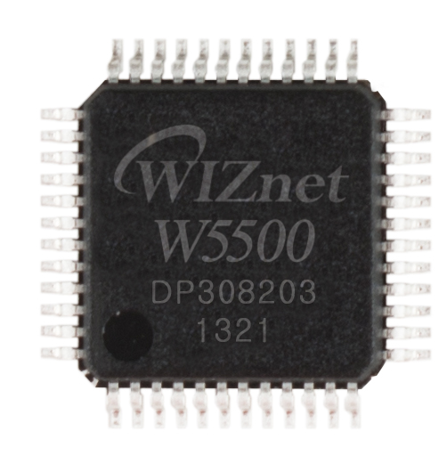
WIZnet - W5500
x 1

Project description
01 Project Context & Development Team
TMCIT Ararobo 2026A is a team from the Arakawa Campus Robot Research Club at Tokyo Metropolitan College of Industrial Technology, a public Japanese college of technology. The team develops robot controllers, networking firmware and ROS 2 software for the 2026 NHK Kosen Robot Contest.
The story here is not merely that a robot uses Ethernet. It is that both manual teleoperation and higher-level ROS 2 control communicate with embedded robot hardware through W5500-based UDP interfaces.
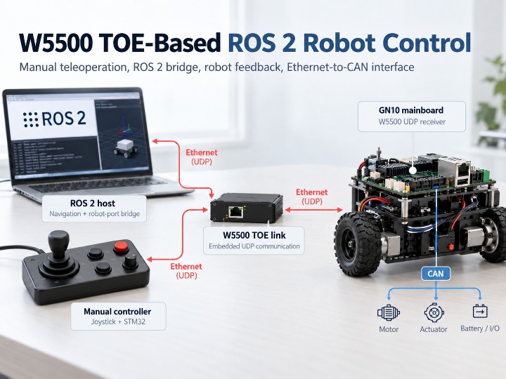
- Manual teleoperation: An STM32 collects joystick and button input and transmits UDP control messages through a W5500 hardware socket.
- ROS 2 control bridge: The
robot-portpackage translates standard ROS 2 Humble messages into binary commands for the mainboard. - Robot feedback: Battery, motor, emergency-stop and mechanism data are exposed to monitoring applications as ROS 2 topics.
- Ethernet-to-CAN interface: GN10 mainboard firmware receives commands over W5500 and interfaces with CAN-connected robot controllers.
The club's affiliation is confirmed by the college and team repositories. The project has not been verified as a separate institutional laboratory research program, and use of this specific controller during actual competition remains unconfirmed. Official club profile
02 Main Functions: Teleoperation, ROS 2 & Feedback
Ethernet teleoperation
robo-con-for-Ethernet packages joystick and button inputs into a compact 8-byte binary UDP command. The firmware configures a nominal 100Hz (10ms) timer and sends the data using a W5500 hardware UDP socket. This is a configured update interval, not a measured end-to-end latency or delivery guarantee.
ROS 2 command translation
On the higher-level computer, robot-port uses ROS 2 Humble. It receives standard messages such as geometry_msgs/Twist, navigation status, target IDs, belt-launcher speed and mechanical commands, then converts them into application-specific UDP packets accepted by the GN10 mainboard.
Bidirectional robot feedback
Feedback travels in the reverse direction. The bridge publishes emergency-stop and overcurrent status, drive battery voltage and current, wheel angular velocities, belt-launcher information, and mechanism states as ROS 2 topics.
Navigation-failure handling
The robot-port logic changes travel and belt-speed commands to zero when localization is explicitly invalid or navigation enters a Fail state. This does not establish a fail-safe stop for every possible loss of ROS input. Real-world emergency-stop behavior and actuator shutdown still require system-level validation.
03 Data Flow: Where TOE Is Used
1. Manual teleoperation path
- Input acquisition: An STM32 collects joystick and button inputs and packages them into an 8-byte control message.
- UDP transmission: The remote controller sends the message through a W5500 hardware UDP socket.
- Network delivery: The configured PC gateway routes traffic to the teleoperation UDP receiver on the GN10 mainboard.
2. ROS 2 operation path
- Higher-level control: The ROS 2 computer generates navigation, motion and mechanism commands.
- Message translation: robot-port translates ROS 2 topics into application-specific binary UDP packets.
- TOE reception: A W5500 hardware UDP socket on GN10 receives the operation commands.
- Robot actuation: The STM32 mainboard firmware interfaces with robot controls and CAN-connected devices.
3. Robot feedback path
Battery, motor, emergency-stop and mechanism information from GN10 travels via UDP back to robot-port, which publishes ROS 2 topics for monitoring applications.
Note: Manual and ROS 2 commands serve separate purposes. Separate receiving paths do not by themselves establish verified mode arbitration or automatic handover behavior.
The GN10 mainboard firmware creates separate W5500 UDP sockets for manual teleoperation and operation commands. It receives compact command packets before interfacing with the rest of the embedded control system and the CAN-connected robot devices.
| Channel | Direction | UDP Port | Payload |
|---|---|---|---|
| Teleoperation | Remote → mainboard network | 10410 | 8 B |
| ROS operation command | ROS 2 host → mainboard | 39244 | 32 B |
| Robot feedback | Mainboard → ROS 2 host | 39244 | 44 B |
| Board request | Mainboard → ROS 2 host | 26574 | 8 B |
Technical distinction: The W5500 does not execute ROS 2 DDS/RTPS middleware directly. ROS message conversion happens in the external robot-port process, while the W5500 handles the UDP/IP communication between that bridge and the embedded mainboard. This is ROS 2 integration using TOE, not DDS implemented inside the W5500.
04 Why Does the W5500 Fit?
Evidence note: The project documentation does not explicitly explain why the developers selected the W5500. The following points are engineering implications of the public firmware and the published chip specifications, not claimed quotations from the team.
- 1. Hardware TCP/IP offload: The W5500 processes protocols including UDP, IPv4 and ARP in hardware, so the embedded application can exchange datagrams without implementing a general software TCP/IP stack on the MCU.
- 2. Independent sockets: W5500 supports up to eight hardware sockets. This firmware demonstrates separate UDP sockets for manual and ROS 2 operation command paths.
- 3. Simple embedded interface: SPI, integrated Ethernet MAC/PHY and 32KB of internal TX/RX memory help separate MCU control logic from network packet management.
- 4. Wired control channel: Wired Ethernet avoids radio-frequency interference on the link. Latency, jitter, and packet-loss benefits for this implementation still require measurement.
Chip capabilities and socket/memory specifications: Official WIZnet W5500 documentation
05 Comparison with Other WIZnet Maker Projects
Two previously published Maker projects show different ways of integrating W5500 networking and ROS 2 robotics.
| Dimension | TMCIT Ararobo 2026A (This case) | ULSTU Buggy | MATE-ROV-2025 |
|---|---|---|---|
| Application | Competition robot: manual & autonomous control | Education/research Ackermann rover | ROV telemetry and control |
| Controllers | STM32 + ROS 2 computer | ESP32 + Jetson | STM32F4 + micro-ROS agent |
| W5500 role | Hardware UDP on remote and mainboard | UDP linking ESP32 and ROS 2 host | UDP transport for micro-ROS |
| ROS approach | External robot-port bridge | ROS 2 ↔ JSON-RPC/UDP | Embedded micro-ROS client |
| CAN involvement | Ethernet-to-CAN robot control | Not a primary documented feature | CAN sensors → ROS topics |
| Distinctive feature | Separate manual and ROS 2 command paths | Ackermann robotics teaching platform | Embedded micro-ROS bridge |
TMCIT keeps ROS 2 on an external computer and uses a lightweight custom UDP protocol on the embedded controllers. MATE-ROV takes a different approach with a micro-ROS client running on the MCU. ULSTU also bridges a ROS 2 host and microcontroller using UDP, but with JSON-RPC messages.


