How Does TALLY-NODE Use W5500 Ethernet and LoRa for Camera Tally Lights?
TALLY-NODE connects video switchers through W5500 Ethernet, then sends camera tally states to LoRa receivers. The paid kit is available by inquiry.
0
Components
Hardware components
WIZnet - W5500
x 1

Standard 10/100 Mbps Ethernet interface in the Licensed Master; camera receivers communicate over LoRa.
Project description
A Camera Light Connected to the Production Network
TALLY-NODE combines a W5500-equipped Master with LoRa camera receivers to show which camera is live and which is next. The TALLY-NODE brand sells the assembled Licensed kit and publishes a separate Free edition for phone-based tally. The paid system connects a video switcher to dedicated lights without running a tally cable to each camera.
A tally light is a small status indicator used during a video production. Program, usually shortened to PGM, means the camera is on the active output; preview, or PVW, means it is selected for the next transition. TALLY-NODE represents these states with red and green receiver LEDs. The camera operator can see the production state while remaining beside the camera.
The Master contains an ESP32-S3 processor, a W5500 Ethernet interface and a LoRa radio. A camera receiver uses the radio link and displays its assigned state. The official product page presents the system as a complete paid kit, with ordering by inquiry. The product, documentation and purchase path were checked on 12 October 2026.
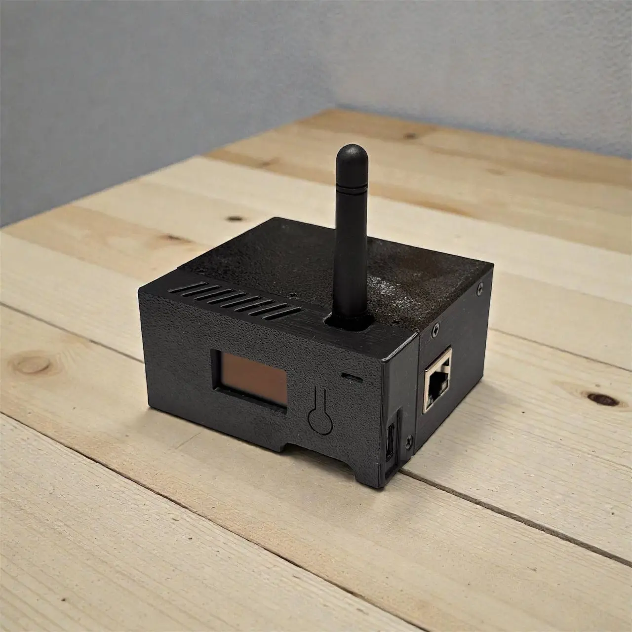 The Master is the bridge between the switcher network and camera receivers. Photo: TALLY-NODE.
Where W5500 Sits in the Signal Path
The technical reference identifies W5500 as the Master-only 10/100 Mbps Ethernet controller. Its RJ45 port connects the Master to the switcher network. The ESP32-S3 application interprets switcher state and distributes the mapped result through LoRa, a low-data-rate wireless technology used here for the final link to camera receivers.
Consider a director selecting camera two. The switcher updates its program state, the Master receives that information over its configured IP connection, and the corresponding receiver shows red. The video picture follows the production system's own video path. TALLY-NODE carries the state information needed to operate the lights.
The wired link is useful when the switcher already belongs to a local Ethernet network. LoRa serves the camera end, while Wi-Fi can provide a separate browser-management connection to the Master. The product therefore has several communication roles, rather than one wireless connection doing every job. The public documents identify W5500 but do not expose its firmware driver, so they leave the implemented TCP/IP processing mode unspecified.
What Travels Over the Switcher Connection
The switcher integration guide lists four supported systems. Their transports differ, so choosing a switcher type also selects the protocol the Master expects.
| Switcher | Documented connection | Setup detail |
|---|---|---|
| Blackmagic ATEM | UDP, port 9910 | Set the switcher IP and input count. |
| OBS Studio | WebSocket, port 4455 | Use the WebSocket 5.x server and matching credentials. |
| vMix | TCP, port 8099 | Receive tally state through the TCP API. |
| OSEE | UDP, port 52381 | Check the connection status after configuration. |
vMix provides a concrete example of the data involved. The official vMix TCP API defines a TALLY response containing one value per input: zero for off, one for program and two for preview. A client can send SUBSCRIBE TALLY to receive subsequent state changes. The Master can therefore turn a compact network message into camera-light state without processing the video itself.
OBS has a different integration requirement. Its WebSocket server lets an external application communicate with OBS over a persistent network connection. TALLY-NODE's guide requires version 5.x; an older 4.x server is not listed as compatible. The supported-system list is the vendor's compatibility documentation, and configuration still depends on the actual switcher and software version in use.
Ethernet for the Switcher, Wi-Fi for Setup
The network guide describes both router-based installation and a direct Master-to-switcher cable. On a network with DHCP, the address-assignment service can give the Master an IP address. The Network screen then reports whether Ethernet hardware is detected, whether a link exists and which address was assigned.
A direct cable requires a different setup because there may be no DHCP server. The Master needs an unused static address in the same subnet as the switcher. A subnet is the local address range whose devices can communicate directly. The corresponding switcher slot should use the Ethernet interface. Wi-Fi, including the Master's access-point mode, remains available for opening the configuration page.
The two interfaces can also serve different switcher connections. The manual gives the example of vMix over Wi-Fi and ATEM over Ethernet. A slot can bind explicitly to either interface; Auto follows the routing table. This makes the network choice a per-connection setting, rather than a single global choice for the entire system.
Map Switcher Inputs to Physical Cameras
TALLY-NODE offers two switcher slots and a separate mapping stage. Each slot defines the available input range. The mapping assigns those inputs to fixed output positions P1 through P20, which correspond to the camera IDs used by the receivers.
For example, P1 could show camera one from the first switcher, while P9 shows camera one from the second. These are different sources even though both switchers call their input “camera one.” Mapping gives the receiver a single position to follow. An unused position can remain blank, and a slot's input count limits which sources can be selected.
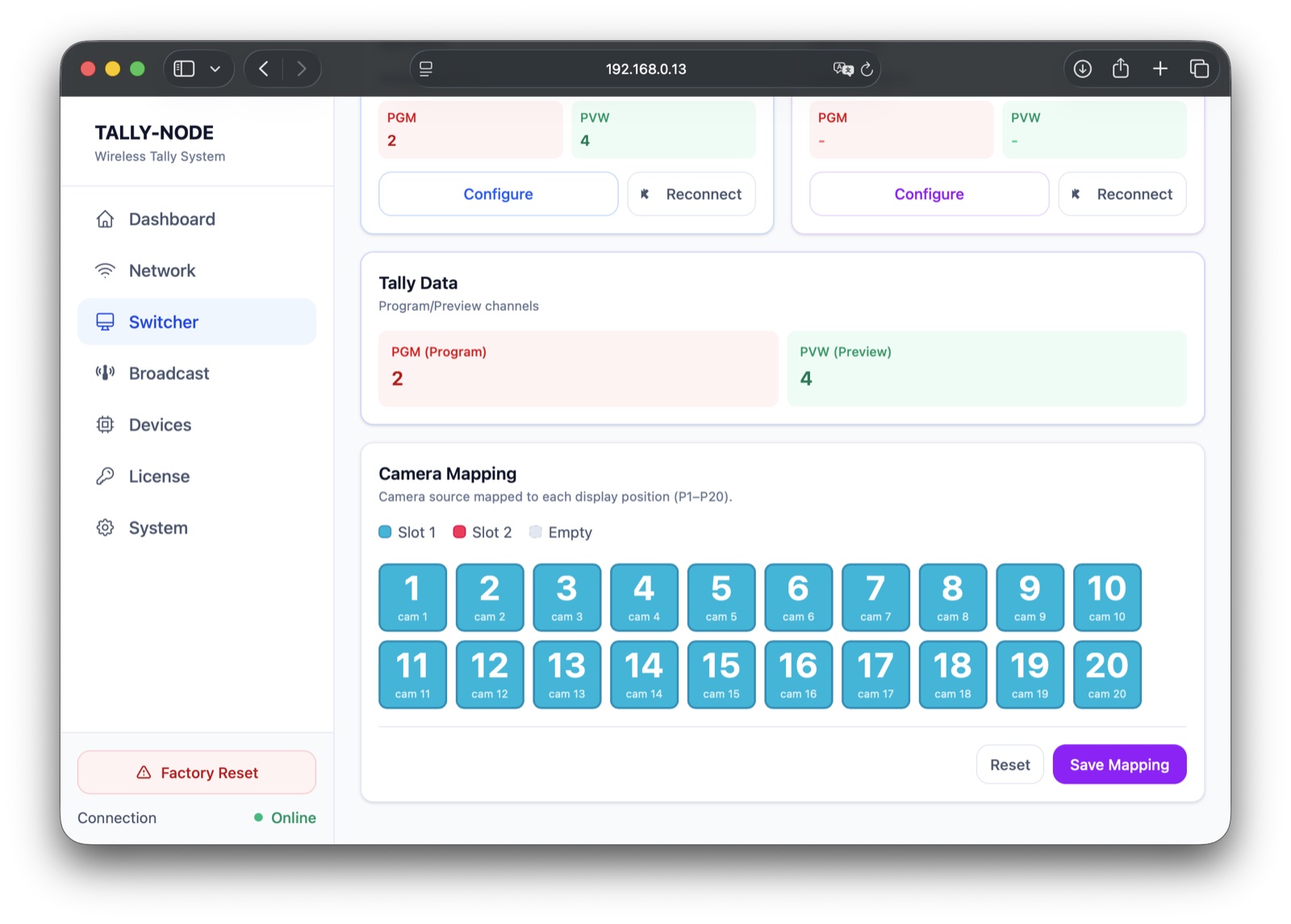 The manufacturer's mapping screen assigns a switcher source to each receiver position. Source: TALLY-NODE Web UI Guide.
The receiver operation guide describes assigning a camera ID with the receiver's button and checking it on the display. The identifier is saved in nonvolatile storage, which retains settings after power is removed. During setup, matching the receiver ID to the intended mapping position is as important as establishing the network connection.
Check the Network, Receiver and Display Separately
The Web UI Guide separates overall status, switcher setup and receiver management. A switcher can be connected while a particular receiver is offline, so the two status views answer different questions. The Devices page shows receiver identity, assigned camera number, online state, signal information and brightness controls.
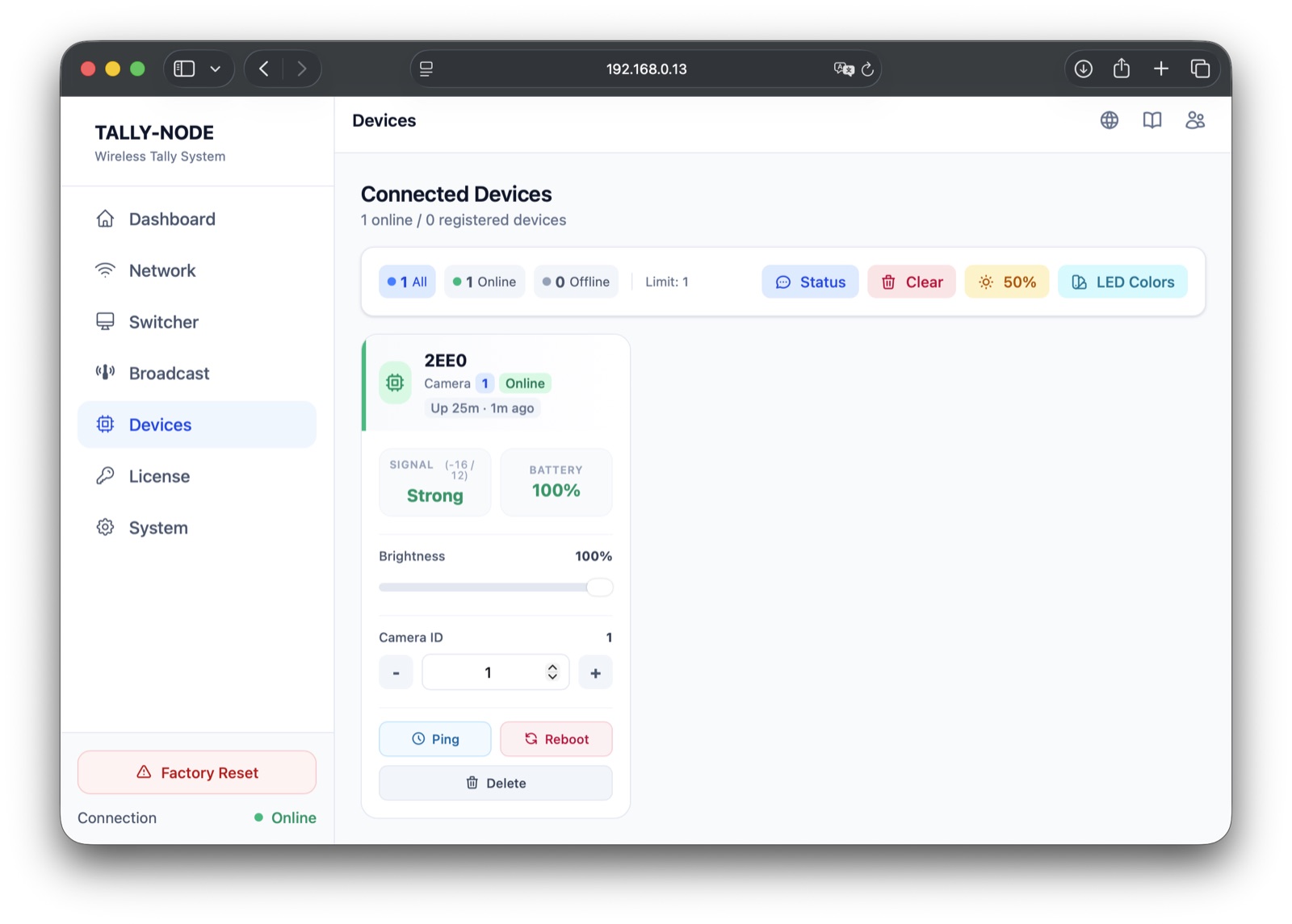 Receiver management includes camera assignment, signal information and brightness. Source: TALLY-NODE Web UI Guide.
Dashboard refresh speed does not measure camera-light latency. The browser periodically requests status, with documented intervals from 0.5 to 5 seconds. Changing that interval changes how quickly the management display refreshes. The vendor describes the Master-to-receiver tally path separately, so a faster web page setting should not be presented as a faster radio link.
The System page also provides a tally test mode that cycles program and preview states across selected channels. That test can help check the receiver assignments and indicators before using switcher-driven state. The guide says test mode generates its own sequence, so it should be stopped before normal operation resumes.
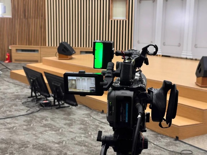
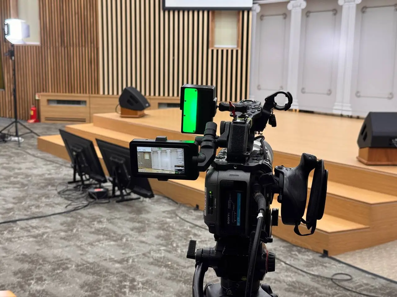 The camera-mounted receiver gives the operator a visible tally indication. Photo: TALLY-NODE.
The technical reference describes the enclosure as intended for indoor use, with no water or dust resistance rating. Receiver placement also affects the radio connection. A useful commissioning check is therefore to walk the intended camera positions and observe receiver status, rather than treating a vendor range estimate as a guarantee for a particular room.
Firmware and License Form Part of the Setup
The firmware guide uses USB-C web flashing and separate Master, Receiver and Free roles. The browser must have access to the connected serial device, and the chosen firmware must match the hardware's role. The guide does not describe over-the-air updating for the Licensed units.
Master and Receiver firmware versions must match, particularly the wireless protocol version. Updating both ends and then checking receiver recognition is therefore part of the documented maintenance flow. A successful flash on one device alone does not establish that the whole system is ready.
The license guide assigns a receiver limit to one Master license. Activation requires an internet connection to the vendor's server. Receivers do not each need their own license. Before ordering, the buyer needs to distinguish three numbers: the system's 20 mapping positions, the purchased receiver quantity and the receiver limit assigned to the Master.
Buying the Kit and Choosing the Right Approach
TALLY-NODE's order page describes an inquiry, a vendor-issued checkout link, payment and shipment from Korea. No public kit price is given. Overseas shipments exclude the 18650 battery. A quote should establish the actual receiver quantity and delivery terms; the advertised maximum does not describe the contents of every order.
The Free edition follows a different path: one ESP32-S3 connects over Wi-Fi and phone browsers display tally. The Licensed kit adds dedicated Master and LoRa receiver hardware. The free software is therefore a separate entry point for phone-based use, rather than a download that supplies the complete commercial system.
For a firmware-oriented alternative, the ESP32-S3 TSL 3.1 project on WIZnet Maker receives Ethernet multicast tally messages and controls a local LED strip. TALLY-NODE instead provides switcher integration, browser setup and a separate radio distribution stage in a licensed kit. The distinction helps a reader choose between a network-connected tally endpoint and a central Master serving multiple camera receivers.
FAQ
Q. Is W5500 optional in the Licensed Master? No. The manufacturer lists W5500 Ethernet as standard Master hardware. Camera receivers use LoRa for their tally connection.
Q. Can Ethernet and Wi-Fi operate together? Yes. The manual supports simultaneous interfaces and selecting an interface for each switcher slot, including Ethernet to a switcher with Wi-Fi for browser access.
Q. Does a kit include 20 receivers? Twenty is the mapping capacity. The order quantity and the Master license's device limit must be confirmed separately.
Q. Does the fastest dashboard setting make the lights respond faster? No. That setting controls browser polling. The manual treats actual tally delivery as a separate process.
Q. What needs checking after a firmware update? Confirm the correct Master and Receiver roles, matching firmware versions, receiver recognition and normal tally operation using the vendor's update procedure.
Documents
-
TALLY-NODE product and kit overview
Licensed Master/Receiver kit, W5500 specifications and original product photos.
-
Technical reference
W5500 Master Ethernet, ESP32-S3 and receiver hardware roles.
-
Switcher integration
ATEM, OBS, vMix and OSEE setup; two slots, camera mapping and interface selection.
-
Network setup
Ethernet and Wi-Fi access, DHCP and direct-switcher static addressing.
-
Master license activation
Internet activation and the receiver limit assigned to each Master license.
-
Kit inquiries and orders
Quote-based ordering, checkout and shipment from Korea; checked 12 October 2026.
-
Free edition DIY guide
Separate ESP32-S3 Wi-Fi phone-tally edition.
-
Official vMix TCP API
TCP port 8099, TALLY states and subscription commands.
-
Web UI and receiver management
Official configuration screens, receiver controls and dashboard polling behavior.
-
Receiver operation and camera IDs
Camera assignment, display modes and receiver operation.
-
Firmware installation and matched versions
USB web flashing, device roles and matched Master/Receiver firmware.


