Aircraft Actuator Test Platform: STM32 and W5500 Modbus TCP Link to a CLICK PLC
A prototype actuator test bench where an STM32 NUCLEO-F446RE uses a WIZ550IO (W5500) as a Modbus TCP server for a CLICK PLUS PLC, plus a Python HMI.
0
Components
Hardware components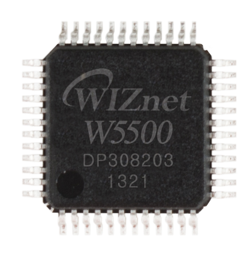
WIZnet - W5500
x 1

HelloWorld-123-star/Aircraft-Actuator-Control-and-Test-Platform
Project description
https://github.com/HelloWorld-123-star/Aircraft-Actuator-Control-and-Test-Platform
Overview
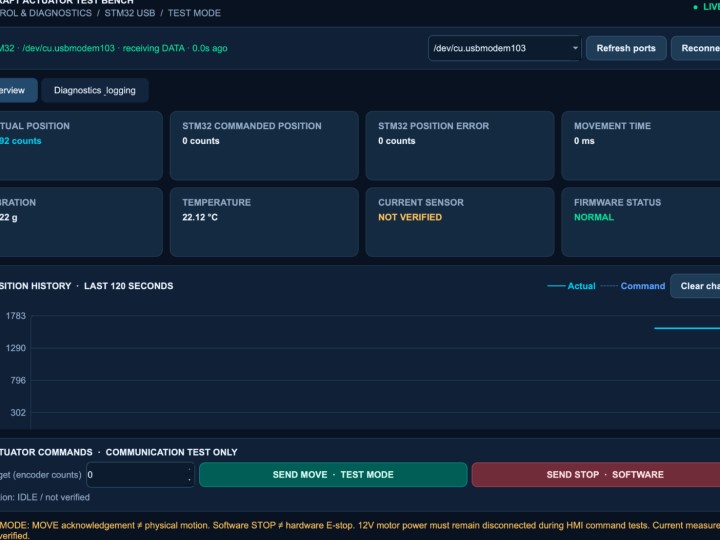
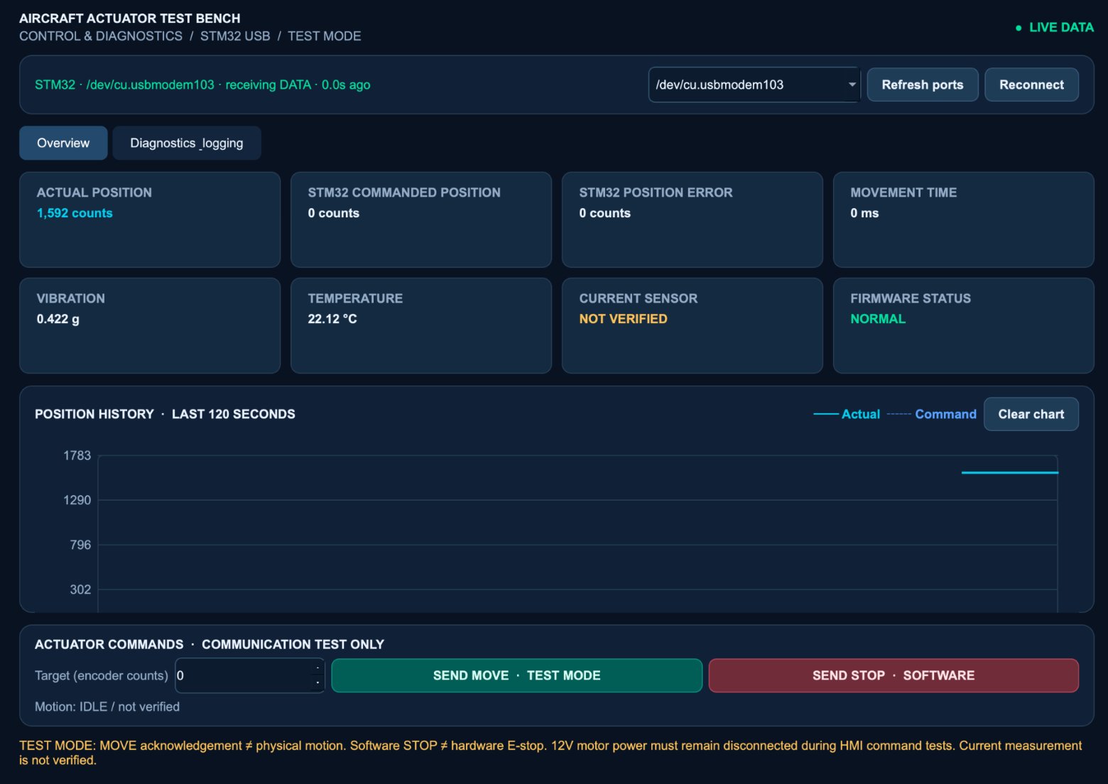
The Aircraft Actuator Control and Test Platform is an embedded test bench in which an STM32 NUCLEO-F446RE drives a 12 V geared DC motor, reads its quadrature encoder and a set of sensors, and exposes its data to a CLICK PLUS C2-01CPU PLC over Modbus TCP through a WIZ550IO Ethernet module built on the WIZnet W5500. A Python HMI on macOS connects to the same STM32 over USB serial for live monitoring and command testing. This description is based on the repository as of 2026-10-19 (last push); the repository has no tagged release.
The author is explicit about scope, and this article follows that wording. The setup is "inspired by aerospace actuator testing", it uses a 12 V DC geared motor "as a prototype rather than an aircraft-certified actuator", and the README closes with: "This is an engineering prototype, not a certified aircraft actuator controller. Software STOP commands do not replace a physical emergency-stop circuit." No aviation certification, flight qualification or performance rating is claimed anywhere in the source, and none is implied here.
What makes the project useful as a reference is the way it documents bring-up. The W5500 link was checked step by step, from a single register read up to a working Modbus TCP server on port 502, and the README records the troubleshooting that was needed to get a real PLC to talk to the board. Motor rotation, encoder feedback, Ethernet, basic PLC logic and HMI messaging are reported as tested. Full closed-loop positioning and physical safety functions are reported as still under development.
Additional photos are available in the original repository: https://github.com/HelloWorld-123-star/Aircraft-Actuator-Control-and-Test-Platform
Hardware & Software Configuration
The README lists the following parts and tools. Every item below is taken from that table.
| Component | Purpose |
|---|---|
| STM32 NUCLEO-F446RE | Main controller and embedded firmware |
| 12 V geared DC motor + driver | PWM motor control |
| Quadrature encoder | Position feedback |
| WIZ550IO / W5500 | Ethernet connection over SPI |
| CLICK PLUS C2-01CPU | PLC communication and Ladder Logic |
| DS18B20 | Motor temperature readings |
| ADXL345 | Vibration measurements over I²C |
| ACS724 | Current sensing (still being tested) |
| Python, PySide6, PySerial | Desktop HMI on macOS |
| STM32CubeIDE, Embedded C, STM32 HAL | Firmware development |
On the STM32, TIM3 generates PWM at 20 kHz for the external motor driver, GPIO pins set the motor direction, and TIM4 runs in encoder mode. SPI1 connects the WIZ550IO, I²C reads the ADXL345, a 1-Wire bus reads the DS18B20, and an ADC input is used for the ACS724 current sensor. UART carries HMI messages and debug output. The HMI talks to the STM32 over USB serial at 115200 baud.
The firmware is written with the STM32 HAL in a main-loop structure, not on an RTOS. The README says FreeRTOS scheduling, CAN, RS-485 / Modbus RTU and Wi-Fi are under consideration, but "these interfaces and RTOS features have not yet been implemented or verified." The current build is a breadboard setup; a custom PCB is listed as a possible later step.
The network uses two static addresses on the same subnet: the STM32 / W5500 at 192.168.1.50 and the CLICK PLUS PLC at 192.168.1.60.
System Architecture
The STM32 is the hub. The motor path and the sensors hang off its timers and serial buses, the HMI reaches it over USB/UART, and the PLC reaches it only through the W5500 on SPI1.
flowchart TB
    HMI["Mac HMI<br/>Python / PySide6"]
    PLC["CLICK PLUS PLC<br/>192.168.1.60<br/>Modbus TCP client"]
    MCU["STM32 NUCLEO-F446RE<br/>HAL main loop"]
    W5500["WIZ550IO / W5500<br/>192.168.1.50<br/>TCP port 502"]
    DRV["Motor driver<br/>TIM3 PWM 20 kHz"]
    ENC["Quadrature encoder<br/>TIM4 encoder mode"]
    MOT["12 V geared<br/>DC motor"]
    SEN["Sensors<br/>ADXL345 I²C<br/>DS18B20 1-Wire<br/>ACS724 ADC"]

    HMI <-->|"USB / UART"| MCU
    PLC <-->|"Ethernet<br/>Modbus TCP"| W5500
    W5500 <-->|"SPI1"| MCU
    MCU --> DRV
    DRV --> MOT
    MOT --> ENC
    ENC --> MCU
    SEN --> MCU
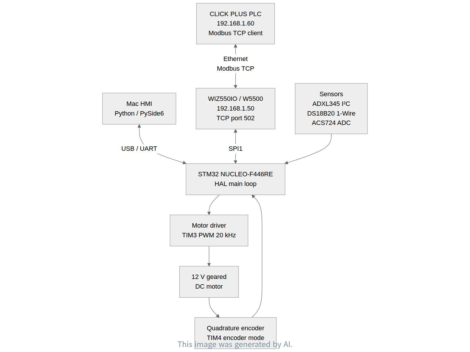
The two outward links carry different traffic. The serial link to the HMI carries text commands such as MOVE,1000 and STOP together with live position, temperature, vibration and status data. The Ethernet link to the PLC carries Modbus TCP register traffic: the PLC reads holding registers from the STM32 (FC03) and writes single or multiple registers to it (FC06, FC16).
On the PLC side, the final CLICK PLUS program has 18 rungs. Rungs 1 to 7 compare the heartbeat in DS6 with the previous value in DS31, set HeartbeatValid (C68) when it changes, and use a 3-second timer (T1) to raise CommTimeout (C59) when updates stop. Rungs 8 to 17 handle the STOP request. StopPending (C111) copies 0 into DS20, a one-shot StopPulse (C114) increments the sequence value in DS22 and sets SendTrigger (C81), and a 500 ms timer (T2) resets the trigger. The FC16 instruction writes three registers starting at DS20 to the STM32, and the FC03 instruction reads four holding registers into DS3 to DS6. The full ladder is published as a PDF in the repository's docs folder.
Role of the WIZnet W5500
The W5500, on a WIZ550IO module, is the only Ethernet interface in the system and the only path between the STM32 and the PLC. The NUCLEO-F446RE connects to it over SPI1. The STM32 acts as the SPI host, configures the chip, and serves Modbus TCP on port 502. The CLICK PLUS PLC is the Modbus TCP client.
The chip is handled directly in the firmware. In Core/Src/main.c, W5500_Reset() resets the Ethernet module and waits for it to restart. W5500_Test() checks SPI communication and prints the result as W5500 SPI Status:%d Version:0x%02X. The HMI code in HMI/main.py is written to skip these W5500 debug lines when it parses STM32 messages, which shows they share the debug UART with the HMI traffic.
The README describes a staged bring-up. First, the VERSIONR register was read and returned the expected value, 0x04. Next, a static IP address was set and read back from the W5500 registers. Then the Ethernet link was checked through the PHYCFGR register, and macOS got 4 out of 4 successful ping replies. Finally, a TCP server was opened on port 502 for Modbus TCP. During debugging, SPI register access, link status, IP configuration, the TCP connection and the Modbus responses were each checked separately.
The data flows in both directions. For writes, the PLC sends a Modbus request over Ethernet to 192.168.1.50:502. The W5500 terminates the TCP connection, and the STM32 reads the received frame over SPI1, decodes the function code and updates its registers. In testing, an FC06 write of the value 123 was received and the PLC success flag was checked, and an FC16 STOP command was confirmed on the STM32 as function code 0x10. For reads, the STM32 builds the FC03 response from its holding registers, including temperature, vibration and heartbeat values, and writes it into the W5500 transmit buffer for the chip to send back to the PLC.
Troubleshooting the Modbus TCP Link
The README records three problems found while connecting a real PLC, and they are useful to anyone putting a W5500 Modbus server on a busy main loop.
The first problem was Modbus response timeouts. The Ethernet link and TCP connection were up, but the PLC reported communication errors. The author checked received Modbus frames, W5500 transmit buffers, socket states and send flags, and found that blocking sensor reads and delays in the STM32 main loop stopped the firmware from answering in time. Temporarily disabling those reads improved communication. Non-blocking sensor scheduling is listed as not yet implemented.
The second was a PLC register conflict. During FC03 sensor testing, the Modbus exception-code destination overlapped with temperature register DS4. Moving it to DS10 fixed the conflict and restored the expected temperature and vibration readings.
The third was FC16 trigger timing. An earlier ladder version reset the send trigger before the FC16 request could reliably execute. After testing trigger conditions and a temporary timer, the author simplified the final program to keep only the basic communication functions.
Test Results and Limitations
The README's test table reports the following results, quoted as written.
| Test | Result |
|---|---|
| STM32 PWM motor rotation | Passed |
| TIM4 encoder feedback | Passed |
| W5500 SPI communication | Passed |
| Ethernet link and ping | Passed |
| Modbus TCP FC03, FC06, FC16 | Passed in basic tests |
| PLC heartbeat and STOP command communication | Passed |
| HMI live display and MOVE/STOP message exchange | Passed |
| HMI-controlled closed-loop motor positioning | Not yet tested |
| ACS724 current measurement | Not yet verified |
| Physical emergency stop and powered STOP behavior | Not yet tested |
| Long-duration system reliability | Not yet tested |
The author also states several limits in the text. The proportional position-control routine, with its target tolerance and 5-second timeout, is not yet connected to the HMI MOVE command. MOVE currently runs in test mode and does not move the motor. The STOP reply confirms only that the command was received, and the PLC STOP test "confirms communication, not physical stopping of a powered motor." DS18B20 readings have sometimes been unstable. The repository has no license file and no stated release version.
FAQ
Is this a certified aircraft actuator controller? No. The README calls it "an engineering prototype, not a certified aircraft actuator controller." It uses a 12 V geared DC motor as a stand-in for an aerospace actuator.
Which side is the Modbus TCP server? The STM32 with the W5500 is the server, listening on TCP port 502 at 192.168.1.50. The CLICK PLUS PLC at 192.168.1.60 is the client.
Which Modbus function codes were tested? FC03 (Read Holding Registers), FC06 (Write Single Register) and FC16 (Write Multiple Registers). The README reports all three as passed in basic tests.
How was the W5500 checked before Modbus was added? By reading VERSIONR (expected 0x04), setting and reading back a static IP, checking the link through PHYCFGR, and getting 4 out of 4 ping replies from macOS.
Does the PLC STOP command physically stop the motor? That has not been tested. The tests confirm that the STM32 receives the FC16 STOP request, and the README notes that software STOP commands do not replace a physical emergency-stop circuit.
About the Author
The project is published on GitHub by HelloWorld-123-star. The GitHub profile gives no name, blog or other contact details. The repository combines STM32 HAL firmware, CLICK PLUS ladder logic and a PySide6 desktop HMI, and its README documents the bring-up, troubleshooting and test results in detail.
개요
Aircraft Actuator Control and Test Platform은 STM32 NUCLEO-F446RE가 12 V 기어드 DC 모터를 구동하고, 쿼드러처 엔코더와 여러 센서를 읽으며, 그 데이터를 WIZnet W5500 기반 WIZ550IO 이더넷 모듈을 통해 Modbus TCP로 CLICK PLUS C2-01CPU PLC에 내주는 임베디드 시험 장치다. 같은 STM32에는 macOS의 Python HMI가 USB 시리얼로 붙어 실시간 모니터링과 명령 시험을 맡는다. 이 글은 2026-10-19(마지막 push) 시점의 저장소를 기준으로 하며, 저장소에는 태그된 릴리스가 없다.
저자는 범위를 분명히 밝히고 있고, 이 글도 그 표현을 따른다. 이 장치는 항공기 액추에이터 시험에서 "착안한" 것이고, 12 V DC 기어드 모터를 "항공 인증 액추에이터가 아닌 프로토타입으로" 쓴다. README는 "This is an engineering prototype, not a certified aircraft actuator controller. Software STOP commands do not replace a physical emergency-stop circuit."라는 문장으로 끝난다. 원본 어디에도 항공 인증, 비행 적합성, 성능 등급에 관한 주장은 없으며, 이 글도 그런 내용을 암시하지 않는다.
이 프로젝트가 참고 자료로 쓸모 있는 이유는 bring-up 과정을 기록한 방식에 있다. W5500 링크를 레지스터 한 번 읽기부터 포트 502에서 동작하는 Modbus TCP 서버까지 단계별로 확인했고, 실제 PLC와 통신하기까지 거친 문제 해결 과정도 README에 남겨 두었다. 모터 회전, 엔코더 피드백, 이더넷, 기본 PLC 로직, HMI 메시지 교환은 시험을 마쳤다고 밝힌다. 완전한 폐루프 위치 제어와 물리적 안전 기능은 아직 개발 중이라고 한다.
추가 사진은 원본 저장소에서 볼 수 있다: https://github.com/HelloWorld-123-star/Aircraft-Actuator-Control-and-Test-Platform
하드웨어·소프트웨어 구성
README에 실린 부품과 도구는 다음과 같다. 아래 표의 모든 항목은 그 표에서 가져왔다.
| 부품 | 용도 |
|---|---|
| STM32 NUCLEO-F446RE | 메인 컨트롤러, 임베디드 펌웨어 |
| 12 V 기어드 DC 모터 + 드라이버 | PWM 모터 제어 |
| 쿼드러처 엔코더 | 위치 피드백 |
| WIZ550IO / W5500 | SPI 기반 이더넷 연결 |
| CLICK PLUS C2-01CPU | PLC 통신, 래더 로직 |
| DS18B20 | 모터 온도 측정 |
| ADXL345 | I²C 진동 측정 |
| ACS724 | 전류 측정(시험 중) |
| Python, PySide6, PySerial | macOS 데스크톱 HMI |
| STM32CubeIDE, Embedded C, STM32 HAL | 펌웨어 개발 |
STM32에서는 TIM3가 외부 모터 드라이버용 20 kHz PWM을 만들고, GPIO 핀이 모터 방향을 정하며, TIM4가 엔코더 모드로 동작한다. SPI1에는 WIZ550IO가, I²C에는 ADXL345가, 1-Wire 버스에는 DS18B20이 붙고, ACS724 전류 센서는 ADC 입력으로 읽는다. UART는 HMI 메시지와 디버그 출력을 함께 실어 나른다. HMI는 115200 baud USB 시리얼로 STM32와 통신한다.
펌웨어는 RTOS 없이 STM32 HAL과 메인 루프 구조로 짜여 있다. README는 FreeRTOS 스케줄링, CAN, RS-485 / Modbus RTU, Wi-Fi를 검토하고 있다고 하면서도 "these interfaces and RTOS features have not yet been implemented or verified"라고 밝힌다. 지금은 브레드보드 구성이며, 커스텀 PCB는 이후에 해 볼 수 있는 단계로 적혀 있다.
네트워크는 같은 서브넷의 고정 주소 두 개를 쓴다. STM32 / W5500은 192.168.1.50, CLICK PLUS PLC는 192.168.1.60이다.
시스템 구조
STM32가 중심이다. 모터 경로와 센서는 STM32의 타이머와 직렬 버스에 연결되고, HMI는 USB/UART로, PLC는 SPI1에 붙은 W5500을 통해서만 STM32에 닿는다.
바깥으로 나가는 두 링크는 실어 나르는 내용이 다르다. HMI와의 시리얼 링크는 MOVE,1000, STOP 같은 텍스트 명령과 실시간 위치·온도·진동·상태 데이터를 주고받는다. PLC와의 이더넷 링크는 Modbus TCP 레지스터 트래픽을 나른다. PLC는 STM32의 홀딩 레지스터를 읽고(FC03), 단일 또는 다중 레지스터를 쓴다(FC06, FC16).
PLC 쪽 최종 CLICK PLUS 프로그램은 18개 rung으로 이루어진다. Rung 17은 DS6의 하트비트를 DS31의 이전 값과 비교해 값이 바뀌면 HeartbeatValid(C68)를 세우고, 갱신이 멈추면 3초 타이머(T1)로 CommTimeout(C59)을 올린다. Rung 817은 STOP 요청을 처리한다. StopPending(C111)이 DS20에 0을 복사하고, 원샷 StopPulse(C114)가 DS22의 시퀀스 값을 올리면서 SendTrigger(C81)를 세우며, 500 ms 타이머(T2)가 트리거를 리셋한다. FC16 명령은 DS20부터 레지스터 3개를 STM32에 쓰고, FC03 명령은 홀딩 레지스터 4개를 DS3~DS6으로 읽어 온다. 래더 전체는 저장소 docs 폴더에 PDF로 올라와 있다.
WIZnet W5500의 역할
WIZ550IO 모듈에 실린 W5500은 이 시스템의 유일한 이더넷 인터페이스이자 STM32와 PLC를 잇는 유일한 경로다. NUCLEO-F446RE는 SPI1로 W5500에 연결된다. STM32가 SPI 호스트로서 칩을 설정하고 포트 502에서 Modbus TCP를 서비스한다. CLICK PLUS PLC는 Modbus TCP 클라이언트다.
펌웨어는 칩을 직접 다룬다. Core/Src/main.c의 W5500_Reset()은 이더넷 모듈을 리셋한 뒤 재시작을 기다린다. W5500_Test()는 SPI 통신을 점검하고 그 결과를 W5500 SPI Status:%d Version:0x%02X 형식으로 출력한다. HMI/main.py는 STM32 메시지를 파싱할 때 이 W5500 디버그 줄을 건너뛰도록 짜여 있다. 이 출력이 HMI 트래픽과 같은 디버그 UART를 쓴다는 뜻이다.
README는 bring-up을 단계별로 설명한다. 먼저 VERSIONR 레지스터를 읽어 기대값 0x04를 얻었다. 다음으로 고정 IP를 설정하고 W5500 레지스터에서 다시 읽어 확인했다. 이어 PHYCFGR 레지스터로 이더넷 링크를 점검했고, macOS에서 ping 4회 중 4회 응답을 받았다. 마지막으로 Modbus TCP용 TCP 서버를 포트 502에 열었다. 디버깅 중에는 SPI 레지스터 접근, 링크 상태, IP 설정, TCP 연결, Modbus 응답을 하나씩 따로 확인했다.
데이터는 양방향으로 흐른다. 쓰기의 경우 PLC가 이더넷으로 192.168.1.50:502에 Modbus 요청을 보낸다. W5500이 TCP 연결을 종단하고, STM32는 SPI1로 수신 프레임을 읽어 기능 코드를 해석한 뒤 레지스터를 갱신한다. 시험에서는 FC06으로 값 123을 써서 PLC 성공 플래그를 확인했고, FC16 STOP 명령이 STM32에서 기능 코드 0x10으로 수신되는 것을 확인했다. 읽기의 경우 STM32가 온도·진동·하트비트 값을 담은 홀딩 레지스터로 FC03 응답을 만들어 W5500 송신 버퍼에 쓰고, 칩이 이를 PLC로 돌려보낸다.
Modbus TCP 링크 문제 해결
README에는 실제 PLC를 연결하면서 찾은 문제 세 가지가 기록되어 있다. 바쁜 메인 루프에 W5500 Modbus 서버를 올리려는 사람에게 참고가 된다.
첫째는 Modbus 응답 타임아웃이다. 이더넷 링크와 TCP 연결은 살아 있었지만 PLC가 통신 오류를 보고했다. 저자는 수신한 Modbus 프레임, W5500 송신 버퍼, 소켓 상태, 송신 플래그를 점검했고, STM32 메인 루프의 블로킹 센서 읽기와 지연 때문에 펌웨어가 제때 응답하지 못한다는 것을 찾아냈다. 이 읽기를 잠시 끄자 통신이 나아졌다. 논블로킹 센서 스케줄링은 아직 구현하지 않았다고 적혀 있다.
둘째는 PLC 레지스터 충돌이다. FC03 센서 시험 중 Modbus 예외 코드 저장 위치가 온도 레지스터 DS4와 겹쳤다. 저장 위치를 DS10으로 옮기자 충돌이 사라지고 온도·진동 값이 제대로 돌아왔다.
셋째는 FC16 트리거 타이밍이다. 이전 래더 버전은 FC16 요청이 확실히 실행되기 전에 송신 트리거를 리셋해 버렸다. 트리거 조건과 임시 타이머를 시험해 본 뒤, 최종 프로그램은 기본 통신 기능만 남기도록 단순화했다.
시험 결과와 한계
README의 시험 표가 보고하는 결과는 다음과 같다. 원문 표현을 그대로 옮겼다.
| 시험 | 결과 |
|---|---|
| STM32 PWM 모터 회전 | Passed |
| TIM4 엔코더 피드백 | Passed |
| W5500 SPI 통신 | Passed |
| 이더넷 링크와 ping | Passed |
| Modbus TCP FC03, FC06, FC16 | Passed in basic tests |
| PLC 하트비트와 STOP 명령 통신 | Passed |
| HMI 실시간 표시와 MOVE/STOP 메시지 교환 | Passed |
| HMI 제어 폐루프 모터 위치 제어 | Not yet tested |
| ACS724 전류 측정 | Not yet verified |
| 물리적 비상 정지와 전원 인가 상태 STOP 동작 | Not yet tested |
| 장시간 시스템 신뢰성 | Not yet tested |
저자는 본문에서도 몇 가지 한계를 밝힌다. 목표 허용 오차와 5초 타임아웃을 갖춘 비례 위치 제어 루틴은 아직 HMI MOVE 명령에 연결되지 않았다. MOVE는 지금 시험 모드로만 동작하며 모터를 실제로 움직이지 않는다. STOP 응답은 명령을 받았다는 사실만 확인해 주며, PLC STOP 시험은 "confirms communication, not physical stopping of a powered motor"라고 적혀 있다. DS18B20 값은 때때로 불안정했다. 저장소에는 라이선스 파일도, 명시된 릴리스 버전도 없다.
자주 묻는 질문
인증받은 항공기 액추에이터 컨트롤러인가? 아니다. README는 이 장치를 "an engineering prototype, not a certified aircraft actuator controller"라고 부른다. 항공 액추에이터 대신 12 V 기어드 DC 모터를 쓴다.
Modbus TCP 서버는 어느 쪽인가? W5500이 붙은 STM32가 서버이며, 192.168.1.50의 TCP 포트 502에서 대기한다. 192.168.1.60의 CLICK PLUS PLC가 클라이언트다.
어떤 Modbus 기능 코드를 시험했나? FC03(Read Holding Registers), FC06(Write Single Register), FC16(Write Multiple Registers)이다. README는 세 가지 모두 기본 시험을 통과했다고 보고한다.
Modbus를 올리기 전에 W5500은 어떻게 확인했나? VERSIONR(기대값 0x04)를 읽고, 고정 IP를 설정한 뒤 다시 읽어 확인하고, PHYCFGR로 링크를 점검하고, macOS에서 ping 4회 중 4회 응답을 받는 순서로 확인했다.
PLC의 STOP 명령이 모터를 물리적으로 멈추나? 그 부분은 시험하지 않았다. 시험으로 확인된 것은 STM32가 FC16 STOP 요청을 받는다는 사실까지다. README는 소프트웨어 STOP 명령이 물리적 비상 정지 회로를 대신하지 않는다고 덧붙인다.
저자 소개
이 프로젝트는 GitHub 사용자 HelloWorld-123-star가 공개했다. GitHub 프로필에는 이름, 블로그, 그 밖의 연락처가 없다. 저장소에는 STM32 HAL 펌웨어, CLICK PLUS 래더 로직, PySide6 데스크톱 HMI가 함께 들어 있으며, README가 bring-up, 문제 해결, 시험 결과를 자세히 기록하고 있다.


