RF-UPS-Monitor: Mains Power Monitoring with RP2040 and W5500
A Raspberry Pi Pico and W5500 monitor mains presence over SNMP, with loss/restore traps, LibreNMS integration and a PoE carrier design.
0
Components
Hardware components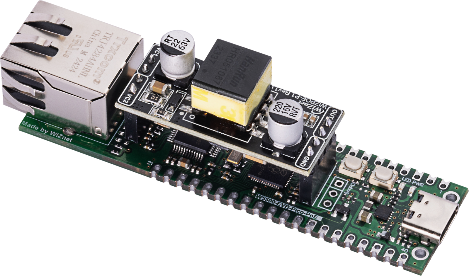
WIZnet - W5500-EVB-Pico-PoE
x 1

Supported integrated RP2040 + W5500 PoE board; alternative to a Pico with an external W5500 module.
Project description
RF-UPS-Monitor: Making Mains Power Visible over W5500 Ethernet
Project curation | Original repository: TheKingOfChaos/RF-UPS-Monitor
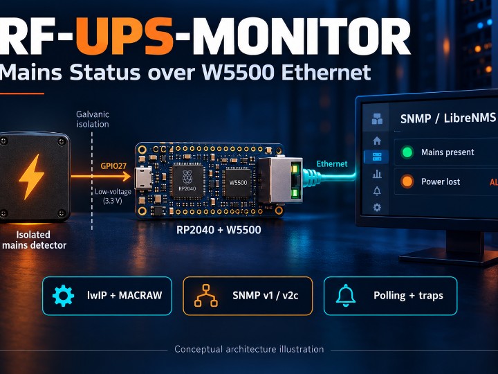
A network can still be reachable while a particular mains circuit has failed. RF-UPS-Monitor turns that local power-presence signal into something a network management system can poll and receive alerts about. The project combines a Raspberry Pi Pico / RP2040, WIZnet W5500 Ethernet, an isolated detector input, and an SNMP agent with LibreNMS integration.
Despite the name, this is a mains-presence monitor. It does not implement a UPS, measure battery capacity, or report the full telemetry of a commercial UPS. Its useful question is simpler: is the monitored mains supply present, and when did that state change?
System architecture
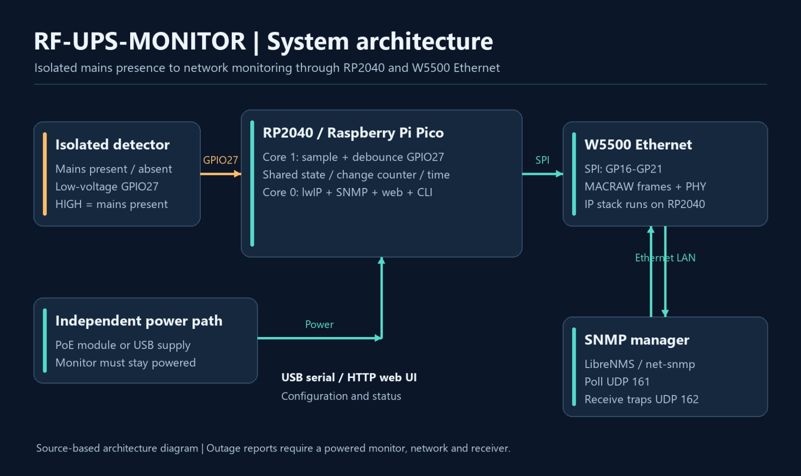
The isolated detector reports mains presence on GPIO27. RP2040 core 1 samples and debounces this input, then shares the state, change count and event time with core 0. Core 0 runs lwIP and the SNMP/web services; the W5500 moves Ethernet frames in MACRAW mode. The manager polls status and receives loss/restore traps, while USB serial or the web interface provides configuration.
Concrete evidence of WIZnet use
The README lists a Pico with a W5500 SPI module and also supports the integrated WIZnet W5500-EVB-Pico-PoE board. src/main.cpp includes W5500lwIP.h, creates a CountingW5500lwIP interface, configures SPI pins, resets the controller, and calls eth.begin(). include/pins.h defines MISO GP16, CS GP17, SCK GP18, MOSI GP19, reset GP20, and interrupt GP21. src/net_stats.cpp also reads the W5500 PHYCFGR register to obtain link information. These are specific implementation references, not just a product tag.
An interesting architectural choice: this project uses the W5500 in MACRAW mode with the RP2040's lwIP software stack. Its IPv4/IPv6 support should therefore not be described as IPv6 being handled by the W5500's hardwired TCP/IP engine. Interface traffic counters are maintained by the firmware; link state and speed come from the W5500 PHY.
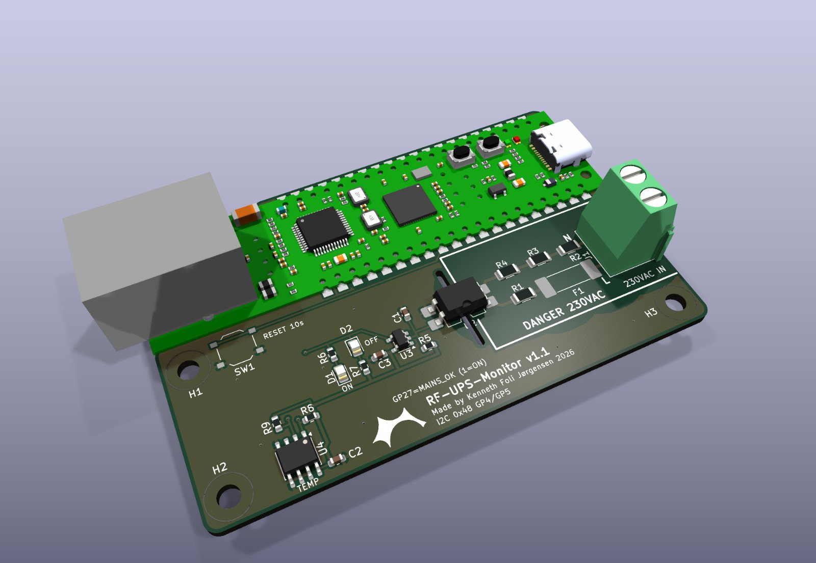
Image source: TheKingOfChaos / RF-UPS-Monitor — iso.png
From a GPIO change to an SNMP alert
An isolated detector produces a low-voltage signal on GPIO27, HIGH for mains present. Core 1 samples and debounces that input, while core 0 handles Ethernet, SNMP, the serial configuration menu, and a web interface. A shared snapshot carries the current state, change count, and last-change time between the cores.
The SNMP agent answers read-only v1/v2c requests on UDP 161. It exposes mains state, transitions, time of last change, board temperature, and IF-MIB interface statistics. Configured traps go to UDP 162 and include mainsPowerLost and mainsPowerRestored. Polling gives periodic visibility; traps provide event notifications. LibreNMS discovery definitions and a custom MIB are included in the repository. The SNMP and web services support dual-stack addressing, while the implemented trap destination is IPv4.
Why the PoE option matters
The carrier design accepts a W5500-EVB-Pico-PoE module and adds an isolated mains detector, status LEDs, a reset button, and a TMP1075 temperature sensor. PoE can let the monitor remain powered separately from the circuit it observes. Reporting an outage still requires the monitor, PoE source, network path, and receiving system to remain powered and reachable. PoE by itself is not backup power.
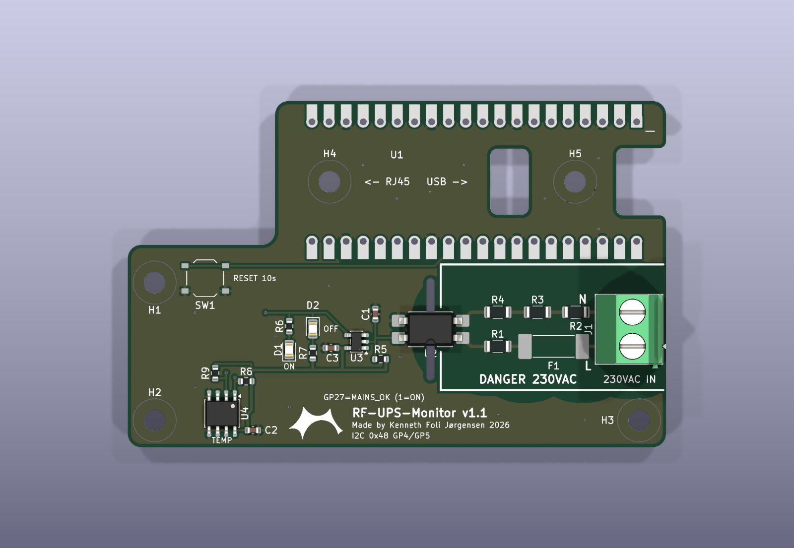
Image source: TheKingOfChaos / RF-UPS-Monitor — top-carrier-only.png
Evidence, limits, and details worth checking
The README reports successful real mains loss/restore and SNMP trap tests. The repository provides on-device Ethernet tests and hardware-in-the-loop code that switches mains and checks loss/restoration traps in both SNMP versions. This curation reviewed the documents and source; it did not rerun those hardware tests or independently certify the hardware. PCB images in the hardware folder are renders, not evidence that the carrier was manufactured.
Several distinctions matter when reproducing the design. The carrier's RC filtering adds about 30–50 ms before a mains-loss signal reaches the firmware, so a software debounce target is not an end-to-end detection-time guarantee. Firmware boardTemperature currently comes from the RP2040 internal sensor; the carrier's TMP1075 is not read yet. The web interface uses plain HTTP, SNMPv1/v2c community strings are unencrypted, and SNMPv3 is unsupported; the repository positions operation on a trusted management network.
For a low-voltage review, start with include/pins.h, src/main.cpp, src/snmp_service.cpp, and the test guide. Mains detector construction is a separate electrical-safety task: the original documentation calls for galvanic isolation, a closed enclosure, upstream protection, and qualified installation. This article is an architecture overview, not a mains-wiring tutorial or safety certification.
Curator's take: the project is compelling because it follows a physical state change all the way into standard network monitoring. W5500 integration, multicore separation, SNMP polling and traps, and hardware-facing tests make it a useful reference for Ethernet-connected monitoring devices.
RF-UPS-Monitor: 정전 여부를 W5500 Ethernet으로 네트워크에 알리다
프로젝트 큐레이션 | 원작 저장소: TheKingOfChaos/RF-UPS-Monitor
네트워크는 살아 있는데 특정 전원 회로만 끊겼다면, 그 상태를 어떻게 원격으로 알 수 있을까? RF-UPS-Monitor는 절연된 전원 감지 입력을 Raspberry Pi Pico / RP2040에서 읽고 W5500 Ethernet을 통해 SNMP로 제공한다. LibreNMS 같은 기존 네트워크 관리 도구에 전원 상태를 연결한다는 점이 흥미롭다.
이름에 UPS가 들어가지만 UPS 자체를 구현하거나 배터리 잔량을 측정하는 프로젝트는 아니다. 핵심은 감시 대상 상용 전원의 존재 여부와 상태 변화 이력을 알리는 것이다.
시스템 아키텍처
절연 감지부가 전원 존재 여부를 GPIO27로 전달합니다. RP2040의 코어 1이 입력을 샘플링·디바운스하고, 현재 상태·변화 횟수·발생 시점을 코어 0과 공유합니다. 코어 0은 lwIP와 SNMP·웹 서비스를 실행하며 W5500은 MACRAW 모드로 Ethernet 프레임을 전달합니다. 관리 서버는 상태를 주기적으로 조회하고 상실·복구 트랩을 받으며, 설정은 USB 시리얼 또는 웹 화면에서 수행합니다.
WIZnet 사용 근거와 네트워크 구조
README는 Pico와 W5500 SPI 모듈 조합, 그리고 WIZnet W5500-EVB-Pico-PoE 보드를 지원 대상으로 명시한다. src/main.cpp에는 W5500lwIP.h, CountingW5500lwIP 객체, 리셋·SPI 설정과 eth.begin() 호출이 있다. include/pins.h는 GP16~GP21의 W5500 연결을 정의하고, src/net_stats.cpp는 PHYCFGR 레지스터에서 링크 정보를 읽는다.
이 프로젝트는 W5500을 MACRAW 모드로 사용하고 RP2040의 lwIP 소프트웨어 스택에서 네트워크를 처리한다. 따라서 IPv6 지원을 W5500 하드웨어 TCP/IP 엔진이 직접 수행한다고 소개하면 부정확하다. 트래픽 통계도 펌웨어가 집계하며 링크 상태와 속도는 W5500 PHY에서 얻는다.
이미지 출처: TheKingOfChaos / RF-UPS-Monitor — iso.png
전원 변화에서 SNMP 알림까지
절연 감지 회로가 GPIO27에 3.3 V 이하의 신호를 제공하며 HIGH가 전원 존재 상태다. 코어 1은 입력 샘플링·디바운스를 담당하고 코어 0은 Ethernet, SNMP, USB 시리얼 메뉴와 웹 설정 화면을 처리한다. 현재 상태·변화 횟수·마지막 변화 시점을 스냅샷으로 공유한다.
SNMP v1/v2c 읽기 요청은 UDP 161에서 처리하고, 설정된 대상의 UDP 162로 전원 상실·복구 트랩을 보낸다. 전원 상태 외에 변화 횟수, 시점, 보드 온도와 IF-MIB 통계도 제공한다. 저장소에는 사용자 MIB와 LibreNMS 탐지·센서 정의가 들어 있다. SNMP·웹 서비스는 IPv4/IPv6를 지원하지만 구현된 트랩 목적지는 IPv4다.
PoE 보드와 캐리어의 의미
캐리어 PCB 설계는 W5500-EVB-Pico-PoE에 절연 전원 감지부, 상태 LED, 리셋 버튼, TMP1075 센서를 더한다. 감시 회로와 별도의 PoE 전원으로 모니터를 유지할 수 있다는 장점이 있다. 다만 정전 중 알림을 받으려면 모니터뿐 아니라 PoE 공급 장치, 네트워크 경로와 수신 시스템도 계속 동작해야 한다. PoE 자체가 백업 전원을 의미하지는 않는다.
이미지 출처: TheKingOfChaos / RF-UPS-Monitor — top-carrier-only.png
검증 범위와 재현 시 확인할 점
README는 실제 전원 차단·복구 및 트랩 시험 성공을 보고한다. 저장소에는 보드에서 W5500과 DHCP를 확인하는 테스트, 실제 전원을 스위칭하고 v1/v2c 트랩을 검사하는 HIL 테스트가 있다. 이 글은 해당 문서와 코드를 검토한 큐레이션이며 하드웨어 시험을 직접 재실행한 결과는 아니다. 캐리어 폴더의 PCB 이미지는 렌더이므로 제작 실물 사진으로 소개하지 않는다.
캐리어 RC 필터는 전원 상실 전달에 약 30~50 ms를 추가하므로 소프트웨어 디바운스 목표를 전체 감지 지연으로 해석하면 안 된다. 현재 펌웨어의 boardTemperature는 RP2040 내부 온도이며 TMP1075는 아직 읽지 않는다. 웹은 평문 HTTP, SNMP v1/v2c는 암호화되지 않은 커뮤니티 문자열을 사용하고 SNMPv3는 지원하지 않으므로 원본 문서가 안내하는 신뢰할 수 있는 관리망 운용을 전제로 봐야 한다.
설계 흐름은 핀 정의, main.cpp, snmp_service.cpp와 테스트 가이드에서 살펴볼 수 있다. 상용 전원 감지 회로 제작은 별도의 전기 안전 검토가 필요하며, 원본은 절연·폐쇄형 케이스·상위 보호 장치와 자격을 갖춘 작업자를 요구한다. 이 글은 구조 소개이며 고전압 배선 설명서나 안전 인증을 대신하지 않는다.
큐레이터 관점: 물리적인 상태 변화를 표준 네트워크 모니터링까지 연결하는 흐름이 잘 드러난다. W5500 연동, 멀티코어 역할 분리, SNMP 폴링·트랩과 하드웨어 테스트를 함께 공부할 수 있는 사례다.
Sources / 출처
README: hardware, status and license
W5500 initialization and multicore flow
MACRAW/lwIP statistics and PHY access
SNMP service and trap destination
Hardware-in-the-loop trap tests
Carrier design and implementation limits
Reviewed on 2026-10-25 against firmware version 2.4.2. The README declares MIT; no standalone top-level LICENSE file was present in the reviewed tree. Third-party assets may have their own notices. Original project credit remains with TheKingOfChaos. Artwork is an AI-generated conceptual illustration, not a photograph or actual monitoring screenshot.
Documents
-
RF-UPS-Monitor firmware and monitoring definitions
Original source by TheKingOfChaos. README declares MIT.
-
W5500-EVB-Pico-PoE carrier design
Original KiCad files, fab outputs and PCB renders; not independently safety certified.
-
Testing guide and hardware-in-the-loop coverage
Author-provided test procedures and code; tests were not rerun for this curation.


