How to Build Distributed Smart Parking Vision with WIZnet W5500 on ESP32-S3 and LuckFox Pico Mini?
LuckFox-PicoMini-ParkingVision is a distributed smart-parking system that combines LuckFox Pico Mini RV1103 edge-AI boards with ESP32-S3
0
Components
Hardware components
WIZnet - W5500
x 1

Project description
Summary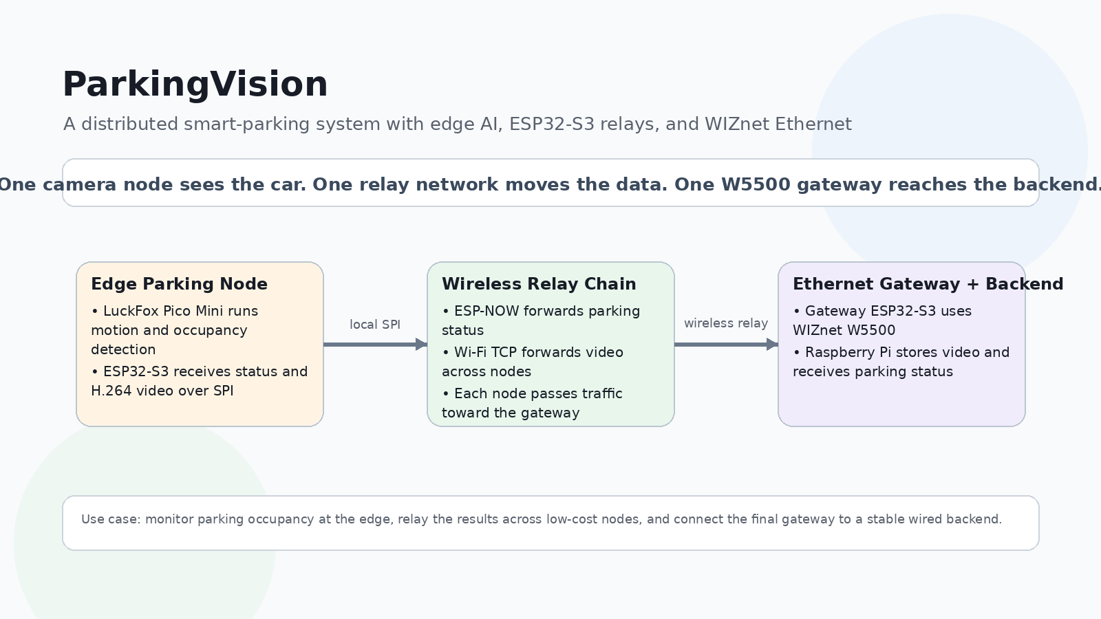
LuckFox-PicoMini-ParkingVision is a distributed smart-parking system that combines LuckFox Pico Mini RV1103 edge-AI boards with ESP32-S3 relay nodes and a Raspberry Pi 4 backend. Each parking node performs local camera processing for motion, vehicle occupancy, and license-plate localization, then forwards status and video through a wireless daisy chain. A WIZnet W5500 on the gateway ESP32-S3 provides the final wired-Ethernet uplink to the Raspberry Pi backend. GitHub
What the Project Does
Each physical parking node contains two processors with separate responsibilities. The LuckFox Pico Mini handles vision processing, while the ESP32-S3 handles transport and network relaying. The two devices communicate over SPI.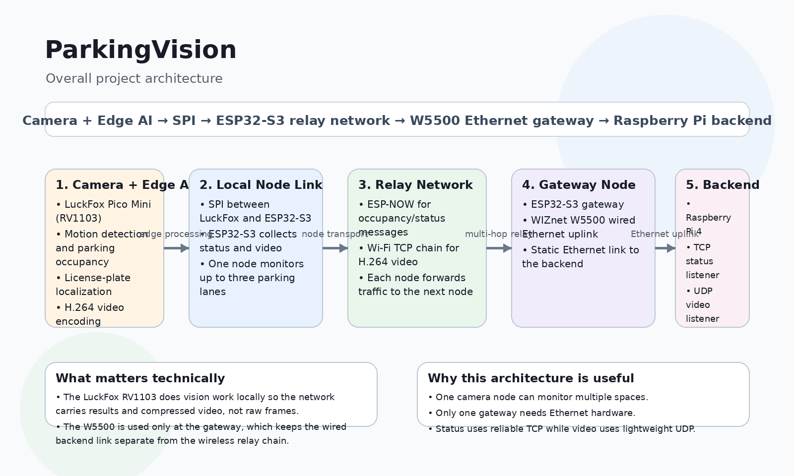
The LuckFox side receives a 1920×1080 NV12 camera frame and divides it into three vertical parking-lane regions. Each region is downsampled to 600×400 for video transport and occupancy processing. This lets one camera monitor three parking spaces independently while preserving a node and stream identifier for each lane.
The vision pipeline is deliberately staged:
Motion detection → settle delay → vehicle detection → occupancy decision → plate localization
Motion detection uses a comparatively inexpensive frame-difference calculation. When motion is detected, the lane enters a settling period rather than immediately running AI inference while a vehicle is still moving. After the wait, an RKNN YOLOv5n model runs on the RV1103 NPU to determine whether a car is actually present. If a parking space becomes occupied, a second model locates the plate region for forwarding to the backend.
Video follows a different path. The RV1103 hardware encoder produces H.264 instead of sending uncompressed frames. The repository reports measurements of roughly 366 KB for the earlier PNG representation versus about 21 KB for an H.264 I-frame, with nearly unchanged P-frames becoming much smaller. This is important because the video must pass through multiple ESP32-S3 relay nodes before reaching the gateway.
The ESP32-S3 network forms a one-way chain rather than a mesh or closed ring. Every node generates its own parking information while simultaneously forwarding data received from the previous node. Small occupancy/status messages use ESP-NOW with hop-by-hop flow control. Bulk H.264 video uses a parallel Wi-Fi AP/STA TCP daisy chain because the project's ESP-NOW packets are too small for video transport.
The end-to-end architecture is therefore:
Camera → LuckFox RV1103 AI → SPI → ESP32-S3 → wireless relay chain → Gateway ESP32-S3 + W5500 → Ethernet → Raspberry Pi 4
Only one ESP32-S3 needs the Ethernet uplink. The node provisioned with node_id == 0 becomes the gateway while still functioning as a normal parking-lot node. All ESP32-S3 units run the same firmware image.
Where WIZnet Fits
The project uses a WIZnet W5500 on the gateway ESP32-S3.
Its specific responsibility is to bridge the distributed parking network onto a wired connection to the Raspberry Pi 4 backend. The other ESP32-S3 nodes relay information toward this gateway wirelessly; they do not require their own Ethernet interfaces.
The gateway uses the W5500 over SPI3. The current firmware assigns:
- GPIO4 — MOSI
- GPIO5 — MISO
- GPIO6 — SCK
- GPIO7 — CS
- GPIO9 — INT
The project currently runs the W5500 SPI link at 8 MHz. The comments explicitly note that this conservative setting was retained while migrating from an earlier ENC28J60 setup, rather than simultaneously changing both the Ethernet controller and bus timing.
There is another important architectural choice behind these pins. The LuckFox-to-ESP32 link uses the ESP32-S3's SPI2 controller because the ESP32 is operating as a SPI slave on that interface. According to the repository comments, the dedicated IOMUX path proved important for reliable slave operation. The W5500 operates as an SPI peripheral under an ESP32 master, so it can be placed on SPI3 through the GPIO matrix without taking those preferred pins away from the LuckFox link.
The W5500 therefore occupies a carefully chosen position in the architecture:
Vision processing stays on the LuckFox NPU.
Wireless aggregation stays on ESP32-S3.
The W5500 handles the gateway's physical Ethernet connection.
The gateway-to-Raspberry-Pi connection is intentionally simple. It is a direct Ethernet cable with static addressing: the firmware defines the gateway as 192.168.50.2 and the Raspberry Pi Ethernet interface as 192.168.50.1. No DHCP server or Ethernet switch is required for that link.
A technical nuance is worth noting: although the W5500 contains its own hardware TCP/IP engine, this firmware integrates it through Espressif's espressif/w5500 Ethernet component and ESP-IDF network stack. Application code uses normal socket() calls rather than WIZnet ioLibrary hardware-socket APIs. In this implementation, the W5500 is primarily the dedicated wired Ethernet interface rather than a directly managed TOE socket engine.
Implementation Notes
The Ethernet configuration is defined directly in src/ESP32-S3-RAP/main/config.h.
constexpr spi_host_device_t kEthSpiHost = SPI3_HOST;
constexpr int kEthSpiClockMhz = 8;
constexpr int kEthCsPin = 7;
constexpr int kEthSckPin = 6;
constexpr int kEthMisoPin = 5;
constexpr int kEthMosiPin = 4;
constexpr int kEthIntPin = 9;
File: src/ESP32-S3-RAP/main/config.h, lines 61–73.
This code exists to isolate the W5500 onto a separate ESP32-S3 SPI controller while reserving SPI2's preferred IOMUX pins for the more timing-sensitive LuckFox-to-ESP32 slave interface. The use of a dedicated interrupt pin also lets the ESP-IDF W5500 driver respond to received Ethernet traffic without relying on periodic polling.
The actual W5500 initialization appears in src/ESP32-S3-RAP/main/gateway_uplink.cpp:
spiDevCfg.mode = 0;
spiDevCfg.clock_speed_hz = kEthSpiClockMhz * 1000 * 1000;
spiDevCfg.queue_size = 20;
spiDevCfg.spics_io_num = kEthCsPin;

eth_w5500_config_t w5500Config =
    ETH_W5500_DEFAULT_CONFIG(kEthSpiHost, &spiDevCfg);

w5500Config.base.int_gpio_num = kEthIntPin;
File: src/ESP32-S3-RAP/main/gateway_uplink.cpp, lines 315–321.
The firmware then creates ESP-IDF W5500 MAC and PHY objects and installs them as a standard Ethernet interface:
esp_eth_mac_t *mac =
esp_eth_mac_new_w5500(&w5500Config, &macConfig);
esp_eth_phy_t *phy =
esp_eth_phy_new_w5500(&phyConfig);
esp_eth_config_t ethConfig = ETH_DEFAULT_CONFIG(mac, phy);
esp_eth_driver_install(ðConfig, &g_ethHandle);File: src/ESP32-S3-RAP/main/gateway_uplink.cpp, lines 329–345.
That interface carries two different kinds of backend traffic.
Parking status uses TCP on port 5000. Each reading contains the originating node, lane stream, occupancy state, and plate field:
node:stream:occupied:plateThe firmware intentionally performs this work in a separate FreeRTOS task with a bounded connection timeout. If the Raspberry Pi or Ethernet connection fails, the wireless chain is not allowed to block indefinitely waiting for the backend
Video uses a different trade-off. The gateway sends H.264 data to port 5300 using UDP. Individual video frames are split into application-level chunks of 1,400 payload bytes, keeping the resulting UDP packets below the normal 1,500-byte Ethernet MTU. Missing chunks cause that video frame to be discarded rather than retransmitted.
That behavior is deliberate: a lost occupancy update matters, so the project uses TCP for status. A lost video frame can simply be skipped because another frame follows shortly afterward, so UDP avoids spending bandwidth and SPI transactions on retransmission.
The Raspberry Pi listener reflects the same architecture. backend/status_listener.py opens a TCP server on port 5000, while backend/video_listener.py listens for UDP on port 5300, reconstructs frame chunks, and appends them to per-node, per-stream H.264 files.
Practical Tips / Pitfalls
- Treat the W5500 as a gateway resource, not a per-camera requirement. The architecture only needs wired Ethernet on
node_id == 0; adding W5500 modules to every parking node would increase wiring and hardware cost without matching this topology. - Keep the LuckFox SPI link and W5500 SPI link separate. This project assigns the timing-sensitive ESP32 slave interface to SPI2/IOMUX and the W5500 master interface to SPI3. Swapping them without testing could reproduce the SPI reliability problems described in the source comments.
- Use the W5500 interrupt line where possible. The firmware assigns GPIO9 to
INTand configures the ESP-IDF driver around that interrupt instead of relying on periodic polling. - Separate critical telemetry from disposable video. Parking state goes over TCP, while video uses chunked UDP. This prevents video retransmission behavior from consuming bandwidth needed for small but important status messages.
- Avoid IP fragmentation for video. The project's 1,400-byte application chunk size leaves room for UDP/IP headers beneath a normal Ethernet MTU and makes loss recovery operate at the application-frame level.
- Plan for gateway failure. The current one-way chain has no implemented rerouting around a permanently failed node, so a dead relay or gateway can isolate upstream nodes. This is a significant consideration for real parking deployments.
- Do not let backend outages stall the relay chain. The implementation already addresses this with bounded TCP connection attempts and separate queues. Any production backend should preserve that decoupling.
FAQ
Q: Why does this project use the WIZnet W5500?
The W5500 gives the gateway ESP32-S3 a dedicated wired-Ethernet connection to the Raspberry Pi backend while the other nodes continue using wireless links for their local chain. This isolates the backend uplink from the multi-hop parking network and provides a direct RJ45 connection for aggregated status and video traffic. In this particular firmware, ESP-IDF exposes the W5500 as an Ethernet interface to the host networking stack rather than using WIZnet ioLibrary socket APIs directly.
Q: How is the W5500 connected to the ESP32-S3?
The gateway uses SPI3 with MOSI on GPIO4, MISO on GPIO5, SCK on GPIO6, CS on GPIO7, and interrupt on GPIO9. The configured SPI frequency is 8 MHz. The LuckFox SPI connection is kept on the separate SPI2 controller because the ESP32-S3 acts as a slave on that interface and benefits from the dedicated IOMUX path.
Q: What role does the W5500 play specifically in ParkingVision?
It is the final uplink between the distributed parking-node chain and the Raspberry Pi 4 backend. The gateway receives occupancy/status data and H.264 video relayed from other ESP32-S3 nodes, then sends status over TCP port 5000 and chunked video over UDP port 5300 through the W5500 Ethernet interface.
Q: Can beginners reproduce this project?
The W5500 portion alone is manageable for a developer familiar with ESP-IDF and SPI, but the full system is advanced. It combines embedded Linux, RV1103 NPU inference, H.264 hardware encoding, SPI master/slave communication, ESP-NOW, Wi-Fi daisy chaining, FreeRTOS tasks, W5500 Ethernet, TCP/UDP protocols, and a Raspberry Pi backend. A practical learning path would be to validate a single LuckFox–ESP32 pair first, then add the W5500 gateway, and only afterward extend the wireless chain.
Q: How does W5500 Ethernet compare with making the gateway Wi-Fi-only?
A Wi-Fi-only gateway would remove the Ethernet hardware but would force the final backend connection to share the ESP32-S3 radio already handling ESP-NOW and the video daisy chain. The current design gives the final aggregation hop its own wired interface, leaving the radio focused on node-to-node traffic. The trade-off is extra SPI bandwidth, PCB space, and Ethernet hardware at the gateway, but only one W5500 is required for the entire chain.

