How to Build a Managed USB-C Power Controller with WIZnet W6100 on RP2350?
Summary
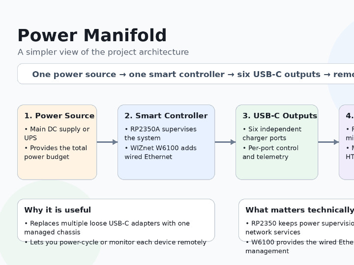
Power Manifold is a six-port managed USB-C Power Delivery supply built around an RP2350 , independent charger blades, and a WIZnet W6100
0
Components
Hardware components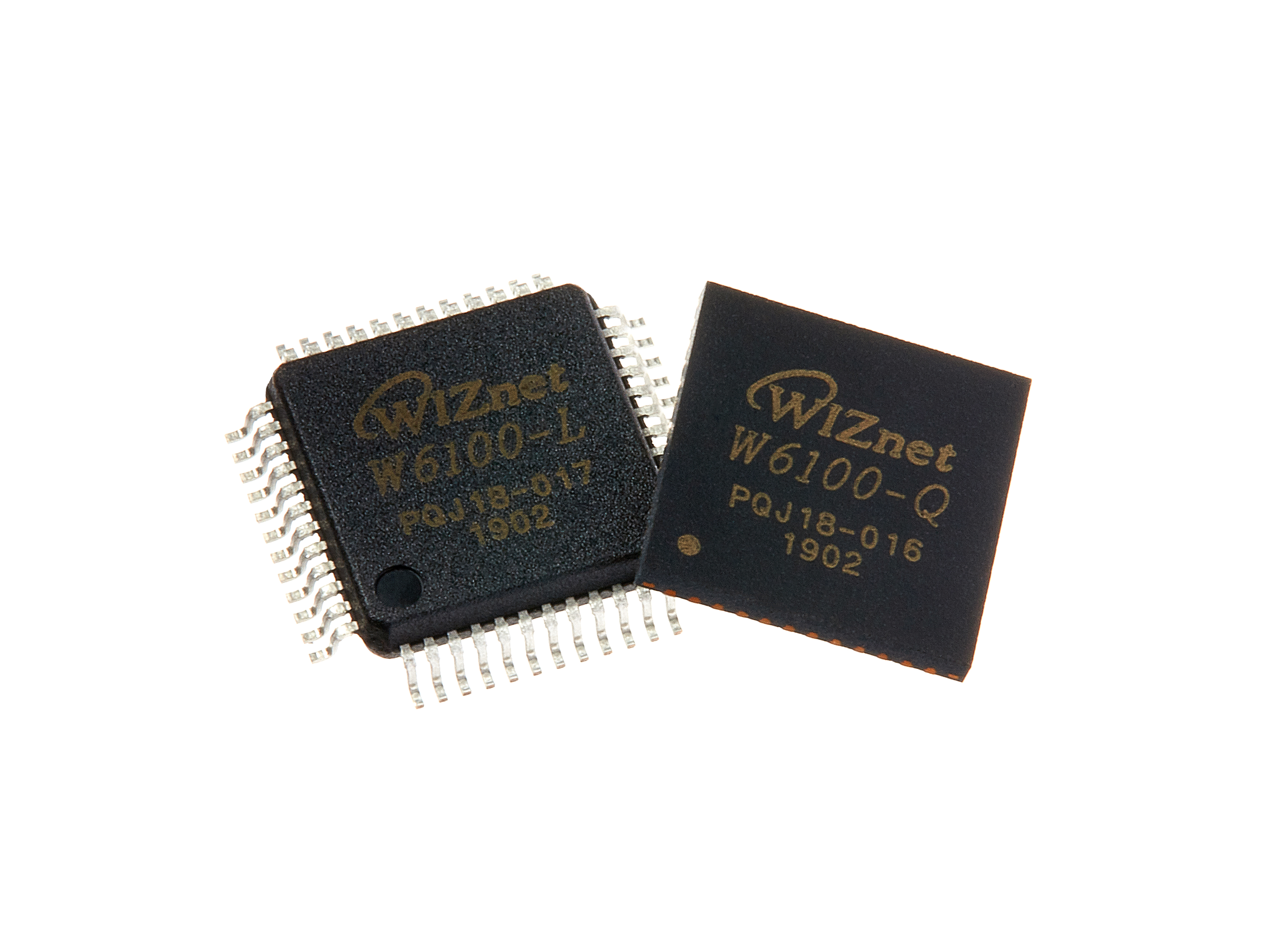
WIZnet - W6100
x 1

Project description
Summary
Power Manifold is a six-port managed USB-C Power Delivery supply built around an RP2350 management controller, independent charger blades, and a WIZnet W6100-L wired-Ethernet interface. It can allocate a shared chassis power budget by port priority while exposing monitoring and control through MQTT, Home Assistant, HTTP, Prometheus, and a local web interface. In the production controller, the W6100 provides the physical wired network path while the RP2350 runs the project's lwIP-based management stack.
What the Project Does
Power Manifold is designed for systems that need to power several USB-C devices from one central supply while retaining per-port control. Typical targets include single-board computers, network appliances, development hardware, and homelab equipment where remotely cycling one load is preferable to rebooting an entire power supply.
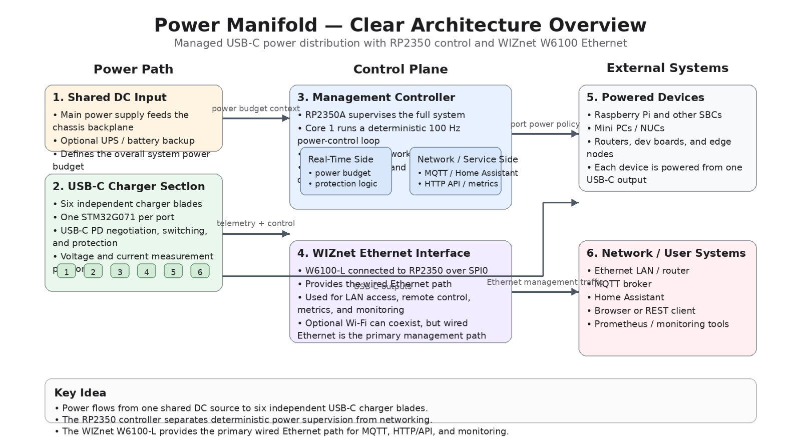
The chassis contains six interchangeable charger blades plus a separate management card. Each charger blade controls one USB-C PD output. The current production architecture uses an STM32G071 on each blade to handle the port-level USB-PD logic, power sequencing, measurement, and fault handling. A TCA9548A I²C multiplexer lets all six identical blades use the same address while remaining electrically separated into individual bus segments.
Above those blades sits an RP2350-based management controller. It polls port telemetry, controls blade enables, enforces the system-wide power budget, manages priority-based throttling, drives the status LEDs, and exposes the entire system to the network. The firmware separates these jobs across both RP2350 cores: core 1 runs a 100 Hz power-supervision loop, while core 0 handles Ethernet, Wi-Fi, MQTT, the HTTP interface, metrics, logging, and configuration.
The resulting data flow is approximately:
USB-C load → charger blade → local measurement/protection → I²C → RP2350 supervisor → W6100/Wi-Fi → MQTT, Home Assistant, REST API, Prometheus
Commands travel in the opposite direction. A user can request that a port be disabled through MQTT or the web/API layer; the management side passes that command to the real-time engine, which then controls the corresponding blade enable while keeping the same state model used by every other interface.
A particularly useful application is a rack or homelab containing SBCs. Instead of using six independent USB-C chargers or a conventional PDU that can only switch AC outlets, Power Manifold can manage the low-voltage USB-PD power delivered to each device and report individual port state and consumption.
Where WIZnet Fits
The production management card contains a WIZnet W6100-L connected to the RP2350A over SPI0. The repository documentation identifies GP16 through GP19 as the W6100 SPI signals, GP20 as reset, and GP21 as the W6100 interrupt. The Ethernet side terminates in a Hanrun HR913550A MagJack, with the W6100 directly driving its link and activity indicators.
The W6100 is therefore located entirely in the management plane:
W6100-L ⇄ SPI0 ⇄ RP2350 core 0 ⇄ management services
It does not negotiate USB-PD, measure the USB-C ports, or participate directly in the real-time power-budget algorithm. Those functions remain local to the charger blades and the core-1 supervisor.
An important architectural detail is that Power Manifold does not simply treat the W6100 as eight hardware TCP/UDP sockets. The firmware documentation explicitly describes the management plane as running lwIP over the W6100 wired interface, alongside lwIP over the CYW43439 Wi-Fi interface. MQTT, HTTP, mDNS, SNTP and the other application services therefore fit into a common network architecture rather than being implemented as separate WIZnet socket applications.
This distinction matters. The W6100 itself provides a hardwired IPv4/IPv6 TCP/IP engine, but a designer can also use its Ethernet capability underneath a host software stack. Power Manifold takes the latter approach so its network services can share the RP2350's management-plane networking model. WIZnet's own W6100 architecture supports both IPv4 and IPv6 and exposes Ethernet through SPI.
The wired interface also coexists with an RM2/CYW43439 radio. When both network paths are available, the project's architecture gives the wired interface the default route. That is a sensible arrangement for equipment whose management connection should remain available without depending exclusively on the local RF environment.
Implementation Notes
The W6100 integration is present in both the production PCB architecture and the controller firmware configuration.
From firmware/controller/boards/pwrman_controller_card.h, the production board definition explicitly identifies the hardware:
// W25Q128 (16 MB) flash, a WIZnet W6100-L on SPI0 GP16-21,
// ...
#define PWRMAN_CONTROLLER_CARD
The comments appear at the beginning of the actual board definition and distinguish the production controller from the Pico 2 W development carrier. They matter because the firmware supports more than one physical management board and must select the correct GPIO and flash configuration at build time.
The same file defines the actual SPI mapping used by the W6100:
// --- SPI (the W6100) ---
#define PICO_DEFAULT_SPI 0
#define PICO_DEFAULT_SPI_SCK_PIN 18
#define PICO_DEFAULT_SPI_TX_PIN 19
#define PICO_DEFAULT_SPI_RX_PIN 16
#define PICO_DEFAULT_SPI_CSN_PIN 17
Source: firmware/controller/boards/pwrman_controller_card.h, lines 49–64.
This establishes the primary host connection as:
- GP16 — MISO
- GP17 — chip select
- GP18 — SPI clock
- GP19 — MOSI
- GP20 — W6100 reset
- GP21 — W6100 interrupt
The separate reset and interrupt signals are documented in the project's controller GPIO map. The interrupt is active while a received frame is waiting, allowing the firmware to react to Ethernet traffic without blindly treating the interface as a continuously polled peripheral.
The broader firmware design is just as important as these pins. Core 1 owns the power-control hardware and runs its supervisor at 100 Hz. Core 0 owns networking. Commands and telemetry cross between them through queues and a seqlock snapshot instead of allowing network handlers to manipulate the backplane directly.
That separation keeps a slow MQTT broker, HTTP request, Wi-Fi event, or Ethernet transaction out of the timing path responsible for USB-C port supervision. It is one of the stronger engineering choices in the project: networking is important, but it is deliberately not allowed to become the real-time controller.
The management side exposes several services over the W6100 path:
- MQTT with optional TLS and Home Assistant discovery
- embedded HTTP/JSON API with optional HTTPS
- Prometheus metrics
- mDNS and SNTP
- UDP syslog forwarding
- DHCP or static addressing
The same controller can also use Wi-Fi. A static address is assigned to the wired interface when a W6100 is present, while the software avoids assigning independent static configurations to both links at once.
The repository also includes host-side verification of the W6100 driver against an emulated chip. That is significant for a management appliance: network-driver behavior can be exercised in automated testing without requiring a physical controller card for every test run.
Practical Tips / Pitfalls
- Keep the W6100 SPI wiring short and controlled. Power Manifold dedicates SPI0 GP16–19 to Ethernet and uses separate reset and interrupt lines. On a custom RP2350 board, routing quality becomes increasingly important as SPI frequency rises.
- Separate network timing from power-control timing. The project's two-core design prevents MQTT, HTTP, DHCP, or retransmission behavior from blocking the 100 Hz supervisory engine. This pattern is worth preserving when adapting the architecture.
- Treat link state as part of system health. Power Manifold reports a problem when its wired link is down and traffic has fallen back to Wi-Fi. For remotely managed power equipment, network availability is operational state rather than merely a connectivity detail.
- Plan grounding and ESD at the RJ45 connector. The production design bonds the RJ45 shield into the chassis structure and handles the magnetics termination as part of its EMI/ESD strategy instead of treating Ethernet as only an SPI-module problem.
- Do not assume that using a W6100 means the application uses its hardware TCP/IP sockets. Power Manifold documents lwIP over the W6100 interface. Hardware choice and network-stack architecture need to be evaluated separately.
- Use deterministic recovery paths. The controller hardware exposes W6100 reset separately, while watchdog supervision covers both RP2350 cores. A managed power controller should have a recovery strategy for both network and control-plane failures.
- Test the driver without depending exclusively on real hardware. The repository's emulated-W6100 host tests provide a useful pattern for regression-testing Ethernet code alongside the rest of the control firmware.
FAQ
Q: Why does Power Manifold use the WIZnet W6100?
The W6100 provides a dedicated 10/100 Ethernet interface that connects cleanly to the RP2350 through SPI while also supporting an IPv4/IPv6-capable architecture. In this project it gives the management controller a wired network path alongside Wi-Fi. The application still uses lwIP on the RP2350, so the main project-specific benefit is the dedicated wired Ethernet interface rather than simply moving all TCP/IP processing into WIZnet hardware sockets.
Q: How is the W6100 connected to the RP2350?
The production controller uses SPI0: GP16 is MISO, GP17 is CS, GP18 is SCK and GP19 is MOSI. GP20 controls W6100 reset and GP21 receives its active-low interrupt. The mapping follows the WIZnet EVB-Pico2 arrangement, which also makes the project's development hardware easier to align with the production controller.
Q: What exactly does the W6100 do in Power Manifold?
It provides the wired Ethernet path for the management plane. Through that interface, the RP2350 can expose MQTT/Home Assistant integration, HTTP and JSON APIs, Prometheus metrics, time synchronization, logging and other network services. It does not control USB-PD directly; real-time blade supervision remains on RP2350 core 1 and on the individual STM32-based charger blades.
Q: Can a beginner reproduce this W6100 design?
The SPI connection itself is approachable, but the complete Power Manifold controller is an advanced embedded-system project. Reproducing it requires familiarity with RP2350 firmware, SPI and I²C, lwIP networking, PCB layout, Ethernet magnetics, USB-PD power electronics, watchdogs and fault handling. A beginner would be better served by first testing the network architecture with an RP2350/W6100 development board before attempting the full multi-board power system.
Q: How does the W6100 wired interface compare with using Wi-Fi alone?
Wi-Fi remains useful in Power Manifold for provisioning and wireless access, and the production controller includes an RM2/CYW43439 radio. Wired W6100 Ethernet adds a physically separate network path and becomes the default route when both links are active. For a fixed device that remotely controls power to other computers, that gives the designer an Ethernet management option that does not depend entirely on RF conditions, while still retaining Wi-Fi as another interface.

