How Does a W5500-EVB-Pico2 Run a Solar Radio Telescope's Front End over Modbus TCP?
MicroPython on a W5500-EVB-Pico2 serves Modbus TCP for EOVSA's front-end controller, applying attenuator and noise-source commands on each 1 PPS edge.
0
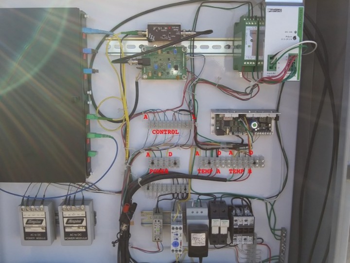
Components
Hardware components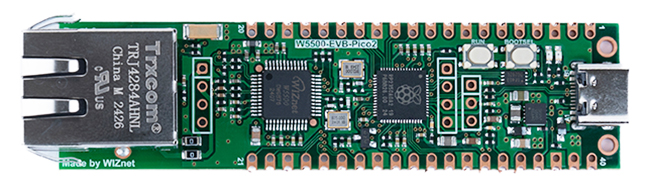
WIZnet - W5500-EVB-Pico2
x 1

Project description
📚 Context: oweng1/EOVSA-FEM-Interface — MicroPython firmware for new front-end interface cards on the 2-m antennas of EOVSA (Expanded Owens Valley Solar Array), the solar radio array NJIT operates at Owens Valley Radio Observatory in California. A W5500-EVB-Pico2 serves Modbus TCP, sets the front-end attenuators and noise source, and reads its power detectors, all on the array's 1 PPS.
01 — Where the card sits
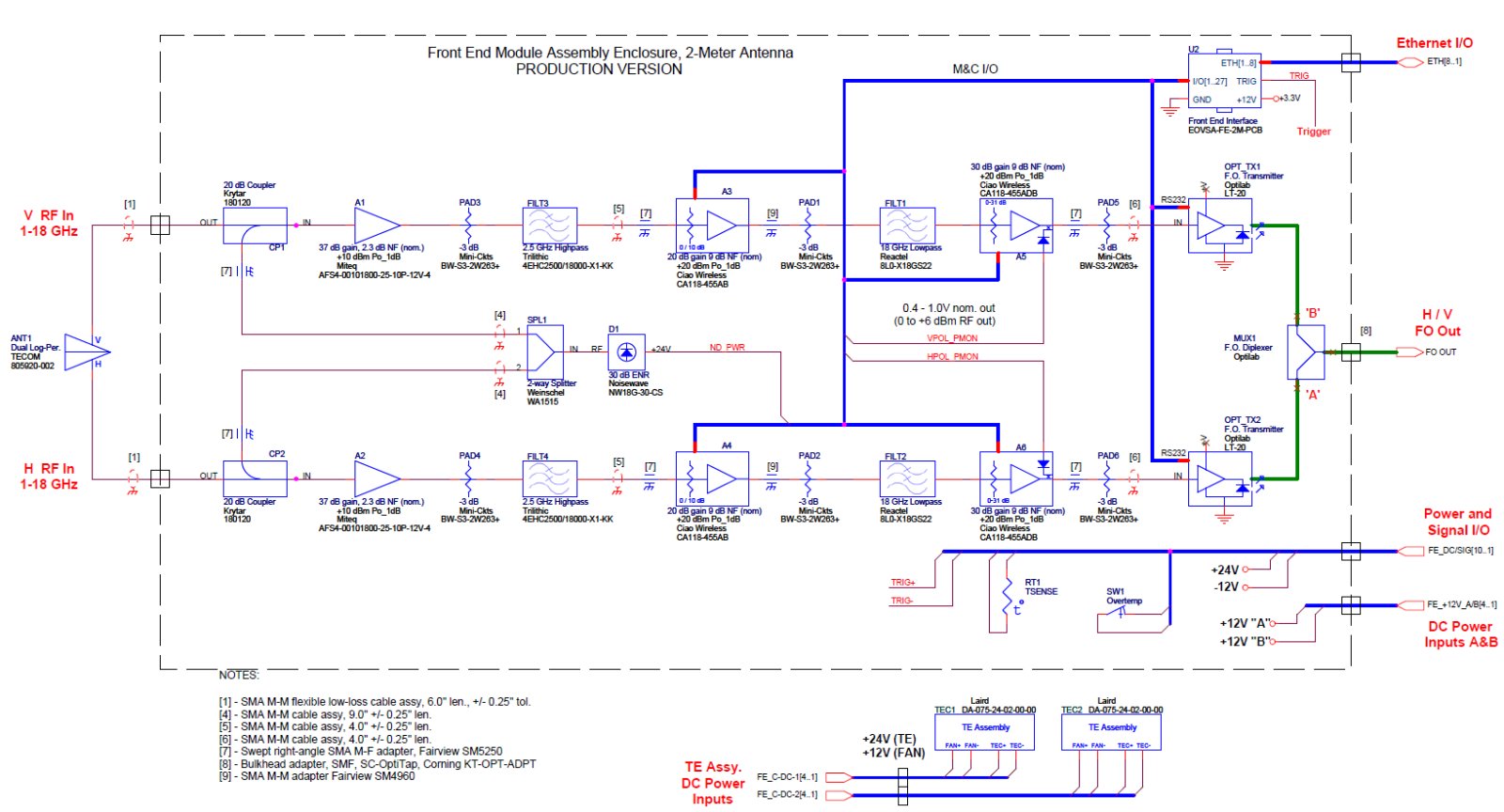
EOVSA observes the Sun every day at 1–18 GHz with fifteen 2-m antennas and a 27-m calibration dish. Behind each 2-m feed is the Front End Module (FEM), a temperature-controlled box with the amplifiers, step attenuators, a calibration noise diode, and the optical transmitters that put both polarizations on one fiber. In the FEM diagram, a Front End Interface block links the box to the antenna network through Ethernet, I/O lines and a trigger input. The repository's card does the same job:
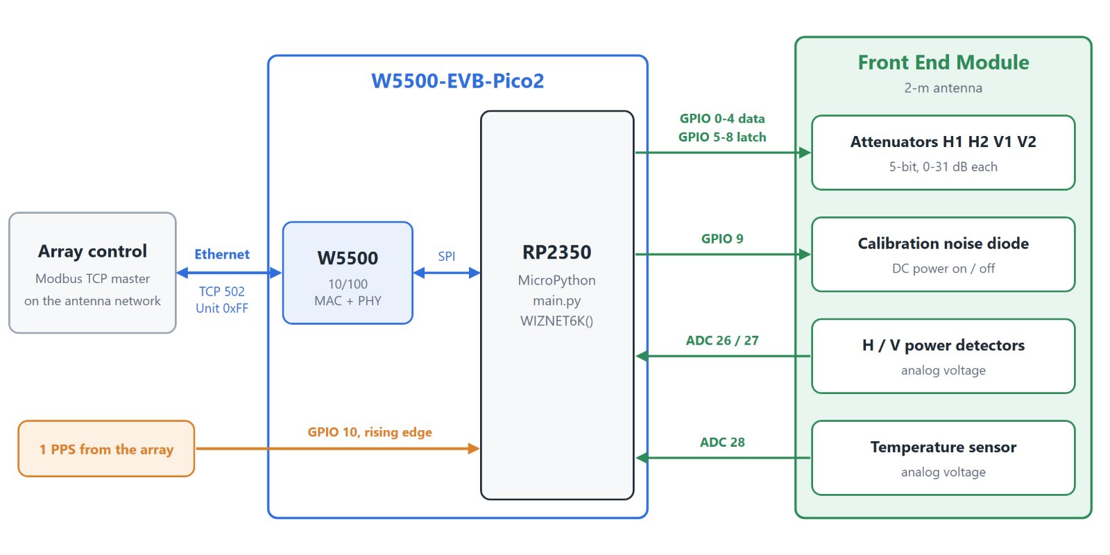
| FEM part | Card side |
|---|---|
| Two step attenuators per polarization, H and V | GPIO 0–4 data bus, GPIO 5–8 latch enables |
| Calibration noise diode | GPIO 9, DC power on or off |
| H and V power detectors | ADC 26, ADC 27 |
| Temperature sensor | ADC 28 |
| 1 PPS trigger | GPIO 10, rising-edge interrupt |
| Antenna network | W5500, Modbus TCP |
02 — The board and the network
| Setting | Value |
|---|---|
| Board | W5500-EVB-Pico2 (RP2350); the README also lists the W5100S and W6100 versions |
| Firmware | MicroPython, WIZnet-ioNIC UF2 build for the EVB-Pico2 |
| Driver | network.WIZNET6K(), onboard SPI pins set by the build |
| Address | DHCP with a MAC-to-IP reservation per front end |
| Service | Modbus TCP server on port 502, Unit ID 0xFF |
| Rollout | one main.py for front ends fe1 to fe16, no per-unit edits |
Because the address comes from the DHCP reservation, the same file goes onto every card. The README's deployment notes are three steps: flash the UF2, save the code as main.py, and repeat across the fleet.
03 — Four attenuators on nine pins
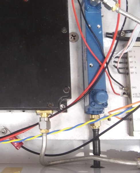
Each polarization has two 5-bit attenuators (0–31 dB). The four share one data bus on GPIO 0–4, and each has its own latch enable on GPIO 5–8. Setting one attenuator means putting the inverted value on the bus and pulsing that attenuator's latch:
def set_attenuators(pol, a1, a2):
    idx = pol * 2                      # 0 = H POL (latches 0, 1), 1 = V POL (latches 2, 3)
    for i, b in enumerate(get_attn_bits(a1)):   # bits = ~value & 31
        attnpins[i].value(b)
    lepins[idx].value(1)
    lepins[idx].value(0)
    # ... same for a2 on latch idx + 1
Nine GPIOs cover twenty attenuator bits, and the other three channels hold their values while one is written.
04 — Every change waits for the second
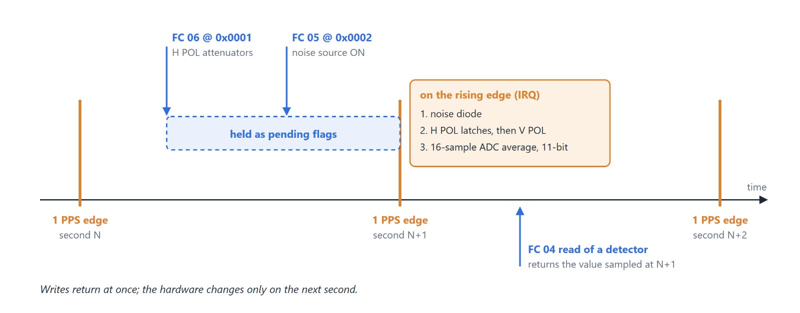
In EOVSA's control commands, a front-end attenuation change takes effect on the next second boundary. The card enforces that itself. A Modbus write only stores the value and sets a flag. The GPIO 10 interrupt does the rest:
def on_rising_edge(pin):              # GPIO 10, 1 PPS
    if setnd:
        set_noisediode(ndval); setnd = False
    if sethpolattn:
        set_attenuators(0, hpola1, hpola2); sethpolattn = False
    if setvpolattn:
        set_attenuators(1, vpola1, vpola2); setvpolattn = False
    latest_hpol_det = read_voltage(0)  # 16-sample average, 11-bit
    latest_vpol_det = read_voltage(1)
    latest_temp = read_temperature()
Every front end therefore switches on the same edge. Each detector reading is tied to a known second, which lets the control system compare antennas and step the attenuation from those readings.
05 — Keeping the programming model
The card implements the "EOVSA 2-Meter Front End Assembly Programming Model", so the software on the other side of the network keeps its register map:
| FC | Address | Use |
|---|---|---|
| 06 | 0x0000 | V POL attenuators: high byte #1, low byte #2, applied on the next 1 PPS |
| 06 | 0x0001 | H POL attenuators, same format |
| 05 | 0x0002 | Noise source power, 0xFF00 on, 0x0000 off, applied on the next 1 PPS |
| 04 | 0x0000, 0x0001, 0x0002 | V detector, H detector, temperature, 0–2047 |
| 04 | 0xFFFF | Firmware revision, currently 2 |
| 01 | 0x0002 | Noise source state |
| 03 | 0x01D4, 2 registers | Attenuator readback V1, V2, H1, H2 |
The RP2350 ADC readings are averaged over 16 samples and scaled to 11 bits, the 0–2047 range the model defines. The model's optical-transmitter commands (FC 03 at 0x0000 and 0x0042, FC 05 at 0x0000 and 0x0001) are marked obsolete and left out.
06 — Staying up at the antenna
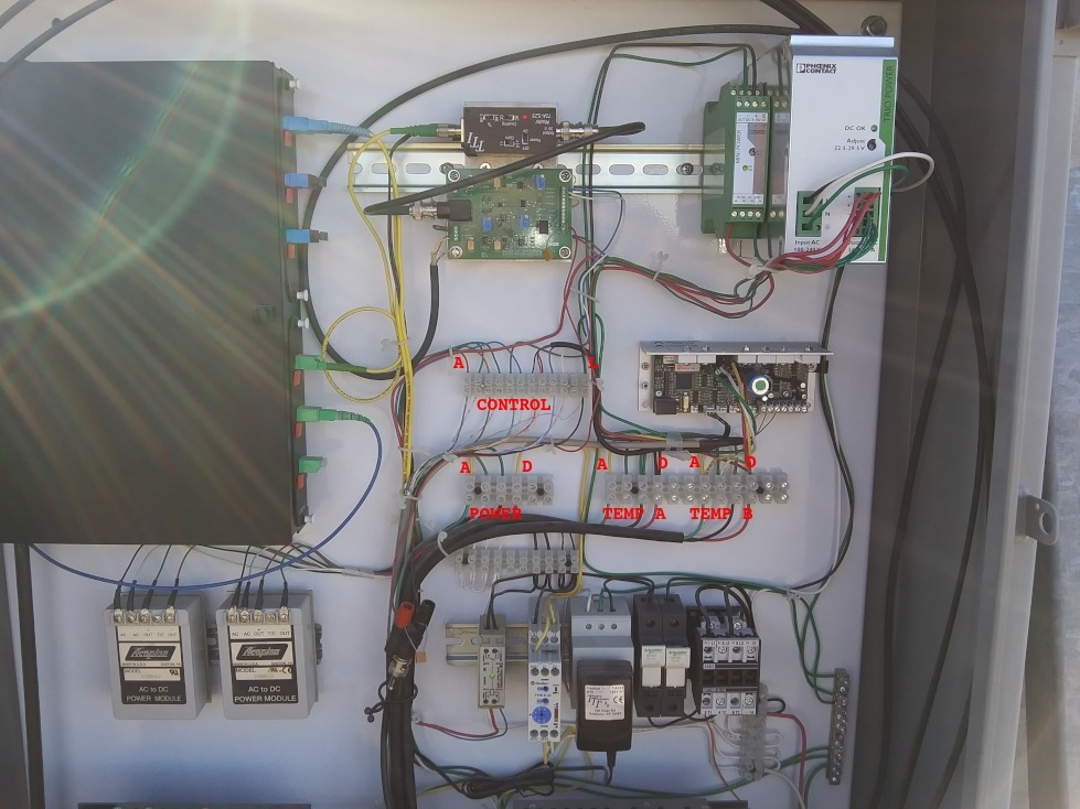
EOVSA's operating notes describe recovering a stuck front-end controller by a remote power cycle, or by the two breakers in the auxiliary box at the antenna. The firmware arms the RP2350 hardware watchdog at 8 s and feeds it from both of its loops:
| Situation | Behaviour |
|---|---|
| No master connected | accept() times out every 1 s, watchdog fed |
| Master connected but silent | recv() times out every 2 s, link checked with nic.isconnected() |
| Link lost | connection closed, back to accept() |
| Firmware hangs | watchdog resets the RP2350 after 8 s, DHCP hands back the reserved address |
07 — Where it stands
- The repository was published on 2026-11-17 with a README and
fem_interface.py. Hostnames, address ranges and the port are masked in the README. - The listing has its debug prints commented out. In the last
exceptblock this leaves the block empty, so it needs apassbefore MicroPython will compile it. The code also imports asecretsmodule that is not in the repository. - The README does not say whether the TOE or the lwIP variant of the WIZnet-ioNIC firmware is flashed.
- There is no license file yet.
One main.py runs the whole front-end fleet, and every attenuator and noise-source change lands on the second.
08 — Similar Projects on WIZnet Makers
- Upgrading of the L-P Band Cryogenic Receiver of the Sardinia Radio Telescope — another radio telescope replacing obsolete receiver control electronics. Its LNA bias board talks Ethernet through a W5100-based module.
- How Does W55RP20 Ethernet Control Ocupoint RF Frontends? — RF front ends configured over Ethernet, here from Go tools using protobuf.
- hispec-fib — the same W5500-EVB-Pico2 in an observatory instrument, running C++ on FreeRTOS to switch fibers for HISPEC, a spectrograph for the Keck telescope.
Q&A
Q. In what mode is the WIZnet chip used? Through MicroPython's network.WIZNET6K() driver in the WIZnet-ioNIC build, with sockets from MicroPython's socket module. The ioNIC releases come in TOE and lwIP variants, and the README does not say which one is used.
Q. Why Ethernet rather than Wi-Fi at the antenna? The repository does not give a reason. EOVSA's RFI notes describe interference near 2 GHz causing non-linearity in the optical link, and the FEM runs 2.5 GHz high-pass filters. A 2.4 GHz radio would sit in the band the array keeps filtering out.
Q. Which boards does it run on? The README lists the W5500-, W5100S- and W6100-EVB-Pico2. The repository description names the W5500 version.
Q. Can it be reused? There is no license file, so ask the author before reusing the code.
Appendix — From the ioNIC build to upstream MicroPython
The firmware runs on the WIZnet-ioNIC MicroPython build, not on an upstream MicroPython release. That build's WIZnet changes are going upstream as a series of pull requests split out of micropython#18035. The first, micropython#19713, was merged on 2026-11-17. It points lib/wiznet5k at WIZnet's ioLibrary_Driver instead of a MicroPython-specific fork, so one driver covers W5100 through W6300. The PR lists the order of the rest:
| Step | Content | State |
|---|---|---|
| 1, micropython#19713 | lib/wiznet5k switched to WIZnet's ioLibrary_Driver; DHCP retransmits on a lost request; MAC and network settings survive active(False) and active(True) | merged 2026-11-17 |
| 2, micropython#19984 | W5100S-, W5500- and W6100-EVB-Pico2 and W6100-EVB-Pico boards on the same driver; DHCP, DNS, TCP and UDP tested on all four with both lwIP and the WIZnet stack | opened 2026-11-20 |
| 3 | machine.PIOSPI on the rp2 port, plus the W6300 and W55RP20 boards | planned |
| 4 | Socket timeout and setsockopt for the WIZnet stack | planned |
For this firmware, that sequence is the path to upstream builds. Step 2, micropython#19984, adds all three boards the README lists. Until it lands, the ioNIC build provides them, which is why the code brings up the interface with network.WIZNET6K(). The socket timeouts its accept and recv loops use come to WIZnet-stack builds in step 4.
Original Link: https://github.com/oweng1/EOVSA-FEM-Interface
Firmware: fem_interface.py · Pinout and register map: README.md · EOVSA front end: Hardware Overview, Attenuation and Level Control, Dealing with RFI


