Designing Prepaid Smart Energy Meter and Deployment in a Network
Designing Prepaid Smart Energy Meter and Deployment in a Network
0
Components
Hardware components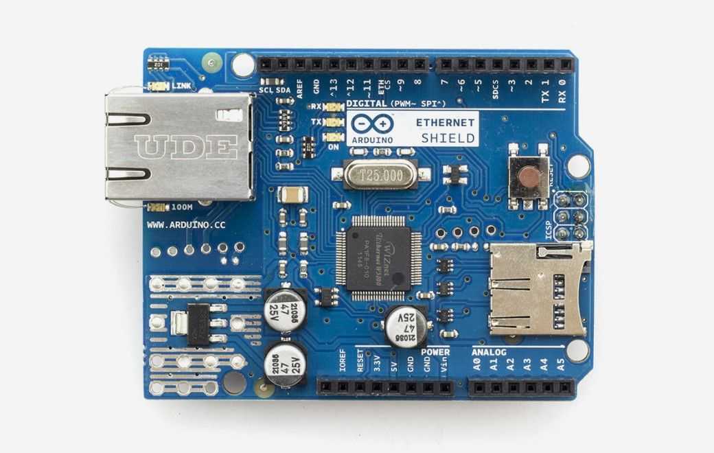
Arduino - Arduino Ethernet Shield
x 1

Arduino Uno Rev3
x 1
Arduino Relay Shield 60A
x 1
Three-Phase Relay PLC
x 1
Adapter
x 1
Arduino - Arduino IDE
x 1
Project description
INTRODUCTION
In developing countries like India, providing everybody with electricity is itself a big challenge. With a growing population and increasing in industries, the need for power also increases. Ineffective distribution creates a considerable gap between the ordinary and the privileged. Few sections of the society have access to unlimited supply of electricity and hence are not paying attention to its misuse. For writing this paper, we got motivation from our college, which has numerous sports complex and common rooms for recreational activities. We observed that students often leave floods lights ON after practice. This lack of responsibility arises because of the unlimited supply of electricity and students having no idea of its actual cost. Our paper focuses on designing a smart meter and connecting multiple smart meters in a network to limit the power wastage. Each meter will act as a node and will be able to communicate with the master computer or Server. The server will store the energy consumption data and it is being displayed on a web portal. The server is storing permitted power consumption in kWh called here as balance. There will be limited balance available for use, it is up to the user to use it wisely. Moreover, the server will give the users full control over each node. This prepaid infrastructure at the institute level will develop the subconscious of using electricity effectively.DEVELOPING A NEW SMART METER
Origin of Smart Meter An electricity meter or energy meter is a device used to measure the amount of electrical energy consumed by the load. Most of these meters are used for billing purposes and are installed at the customer’s end. Energy consumption typically measured in kilowatt-hour(kWh). Otto´ Blathy´ invented the first AC watt-hour meter, but AC meters currently on use operate on the same principle as Blathy’s´ original invention. In the old electromechanical meters, reading was taken by counting revolutions of a non-magnetic and electrically conductive metal disc which is made to rotate at speed proportional to the power passing through the meter. Meter Constant for an energy meter is the amount of energy in kWh used for each revolution of the induction disc. The unit of meter constant is (revolution/kWh). Meters equipped with the ability to have two-way communication with the power company (or other authorized people) are known as smart meters. Few of the peculiarities of the present day Smart Meters are listed below:- Automated and cheap energy consumption data collection system.
- Realtime power usage monitoring.
- Easy implementation of dynamic prices
- Easy fault detection and diagnosis
- High cost of procurement and maintenance.
- Connectivity issue.
- Chances of data theft.
- Lack of customization.
- Considerable startup time after power failure.
 PowerLine Communication
Powerline Communication (PLC) or PowerLine Carrier Communication (PLCC) make use of electrical wires, used to conduct electricity, for communication. It allows user to use the existing wiring infrastructure to provide two or more connected devices with the internet. PLC cuts the additional investment needed to lay ethernet cables for internet connectivity. In PLC data is modulated and filtered and then by using couplers, it is sent over the power lines. PLC can be broadly divided into two types:
PowerLine Communication
Powerline Communication (PLC) or PowerLine Carrier Communication (PLCC) make use of electrical wires, used to conduct electricity, for communication. It allows user to use the existing wiring infrastructure to provide two or more connected devices with the internet. PLC cuts the additional investment needed to lay ethernet cables for internet connectivity. In PLC data is modulated and filtered and then by using couplers, it is sent over the power lines. PLC can be broadly divided into two types:
- Narrowband PLC
- Broadband PLC
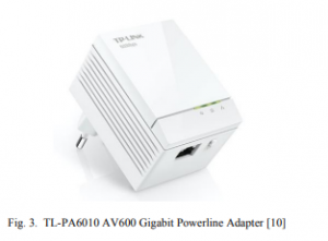
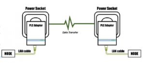 Powerline adapters come in various configurations. Few PLC adapters offer passthrough function, Wi-Fi range extension and higher speeds.
 Arduino With Ethernet Shield
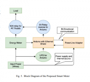
The PLC adapters we used have an RJ45 ethernet port in them, but Arduino does not have RJ45 port. To connect Arduino with PLC adapter, we used Ethernet Shield with Arduino. It is based on the WIZnet W5100 ethernet chip. The WIZnet W5100 provides a network (IP) stack capable of both TCP and UDP. It supports up to four simultaneous socket connections. Arduino communicates with W5100 SPI bus (through the ICSP header). This is on digital pins 11, 12, and 13.
Our designed Smart meter
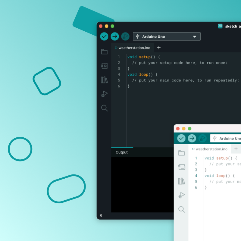
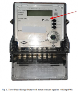
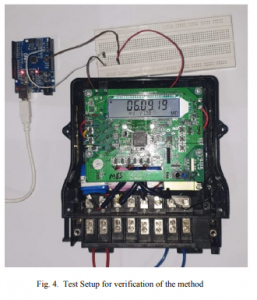
We made a smart meter using the instruments mentioned above. We are using Arduino as the liaison device between the server and the meter. We are using a 60A three-phase energy meter for testing purpose. The meter we used has meter constant equals to 1600imp/sec. That implies that each pulse of the flashing LED equals to 0.000625kWh of energy consumed. The LED is removed, and the input of LED is given to the analog input pins of Arduino. We aim to count the number of transitions from 0 to VCC volts (rising edges or pulses). Arduino will run a programme that will count number of transitions from 0 to VCC volts. This count will serve the basis of our project. Multiplying number of pulses with 0.000625 can give energy consumed in kWh. From the Arduino, a 10A 250V relay is attached which will act as an input for three 20A 250V relays installed at each phase of the three-phase meter. As per the instructions of the server, these relays are used to control the output supply from energy meter.
Arduino With Ethernet Shield
The PLC adapters we used have an RJ45 ethernet port in them, but Arduino does not have RJ45 port. To connect Arduino with PLC adapter, we used Ethernet Shield with Arduino. It is based on the WIZnet W5100 ethernet chip. The WIZnet W5100 provides a network (IP) stack capable of both TCP and UDP. It supports up to four simultaneous socket connections. Arduino communicates with W5100 SPI bus (through the ICSP header). This is on digital pins 11, 12, and 13.
Our designed Smart meter
We made a smart meter using the instruments mentioned above. We are using Arduino as the liaison device between the server and the meter. We are using a 60A three-phase energy meter for testing purpose. The meter we used has meter constant equals to 1600imp/sec. That implies that each pulse of the flashing LED equals to 0.000625kWh of energy consumed. The LED is removed, and the input of LED is given to the analog input pins of Arduino. We aim to count the number of transitions from 0 to VCC volts (rising edges or pulses). Arduino will run a programme that will count number of transitions from 0 to VCC volts. This count will serve the basis of our project. Multiplying number of pulses with 0.000625 can give energy consumed in kWh. From the Arduino, a 10A 250V relay is attached which will act as an input for three 20A 250V relays installed at each phase of the three-phase meter. As per the instructions of the server, these relays are used to control the output supply from energy meter.
 Salient Features of our Smart Meter Explained:
Built-in UPS for zero startup time: whenever there is a power cut or interruption in supply our smart meter will not shut down and hence when power is restored no lag will be observed in collecting readings from energy meter.
Salient Features of our Smart Meter Explained:
Built-in UPS for zero startup time: whenever there is a power cut or interruption in supply our smart meter will not shut down and hence when power is restored no lag will be observed in collecting readings from energy meter.
- High level of accuracy: As Arduino is counting the number of positive pulses from energy meter, least count of our energy meter is (1/1600) kWh=0.000625kWh.
- No operating cost: Data is sent to the server using PowerLine Communication, whereas other smart meters use GSM or internet connection for its connectivity. Hence no need to buy a SIM card and pay for SMS pack or data pack.
- Low cost: In comparison to smart meters available in the market the smart meter designed by us don’t let the old digital meter go to waste and hence a lot cheaper option.
- Hack proof system: Communication using PowerLine is encrypted, and the data will be accessible only by the server.
DEPLOYMENT OF SMART METERS IN COLLEGE CAMPUS
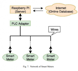
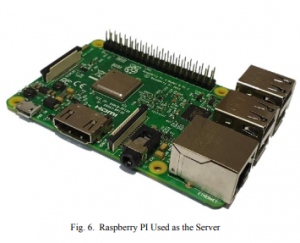
Condition That Electrical Network Must Satisfy The essential precondition for the PLC to work is that all the PowerLine Adapters we wish to connect should be on the SAME electrical network, i.e. there should not be any electrical isolator in between two adapters. Electrical isolator like transformer cannot transfer high-frequency signals without adding noise in the original signals and hence not useful for PLC. Setting Up a Server and Collecting Data. Smart meters are now connected with PLC adapters and are now ready to communicate. One raspberry Pi is used as the server and has the following functions:- Collecting readings (power consumption data) from the smart meters and storing them in a local database.
- Comparing the readings with the available balance.
- Sending readings of each meter to the online database in a periodic manner
- Receive balance information from the online database and instructions from the user to control power supply using relays connected to various Arduino
 The server will count the number of transmissions from each Smart Meter and store them in the form of a table with their timestamp.
As the raspberry pi needs to connect to internet, therefore one more ethernet port will be added to the raspberry pi using USB-to-Ethernet adapter. Raspberry will use one ethernet port for Local Area Connection with smart meters and other to connect to the internet. The authorized users will log in into the online database and make a payment, control each smart meter and monitor energy consumption.
The server will count the number of transmissions from each Smart Meter and store them in the form of a table with their timestamp.
As the raspberry pi needs to connect to internet, therefore one more ethernet port will be added to the raspberry pi using USB-to-Ethernet adapter. Raspberry will use one ethernet port for Local Area Connection with smart meters and other to connect to the internet. The authorized users will log in into the online database and make a payment, control each smart meter and monitor energy consumption.