Skip to content

IOT Battery Charger - W5100S-EVB-PICO with Blynk and Charger

IOT Battery Charger - W5100S-EVB-PICO with Blynk and Charger

ronpang

Published September 20, 2023 · © Apache License 2.0 (Apache-2.0)

IOT Battery Charger - W5100S-EVB-PICO with Blynk and Charger

Components

Hardware components

Project description

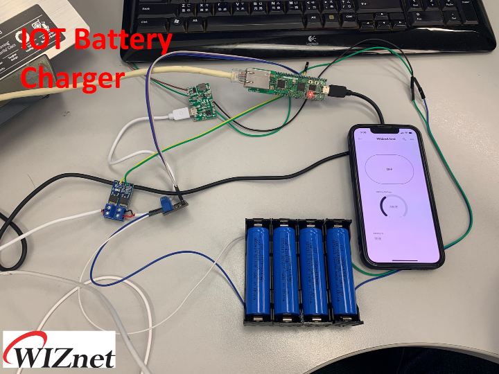
It used W5100S-EVB-PICO to communicate with Blynk to monitor and control battery Charger. (Included Siri feature.)

 
IOT Battery Charger - W5100S-EVB-PICO with Blynk and Charger

Story

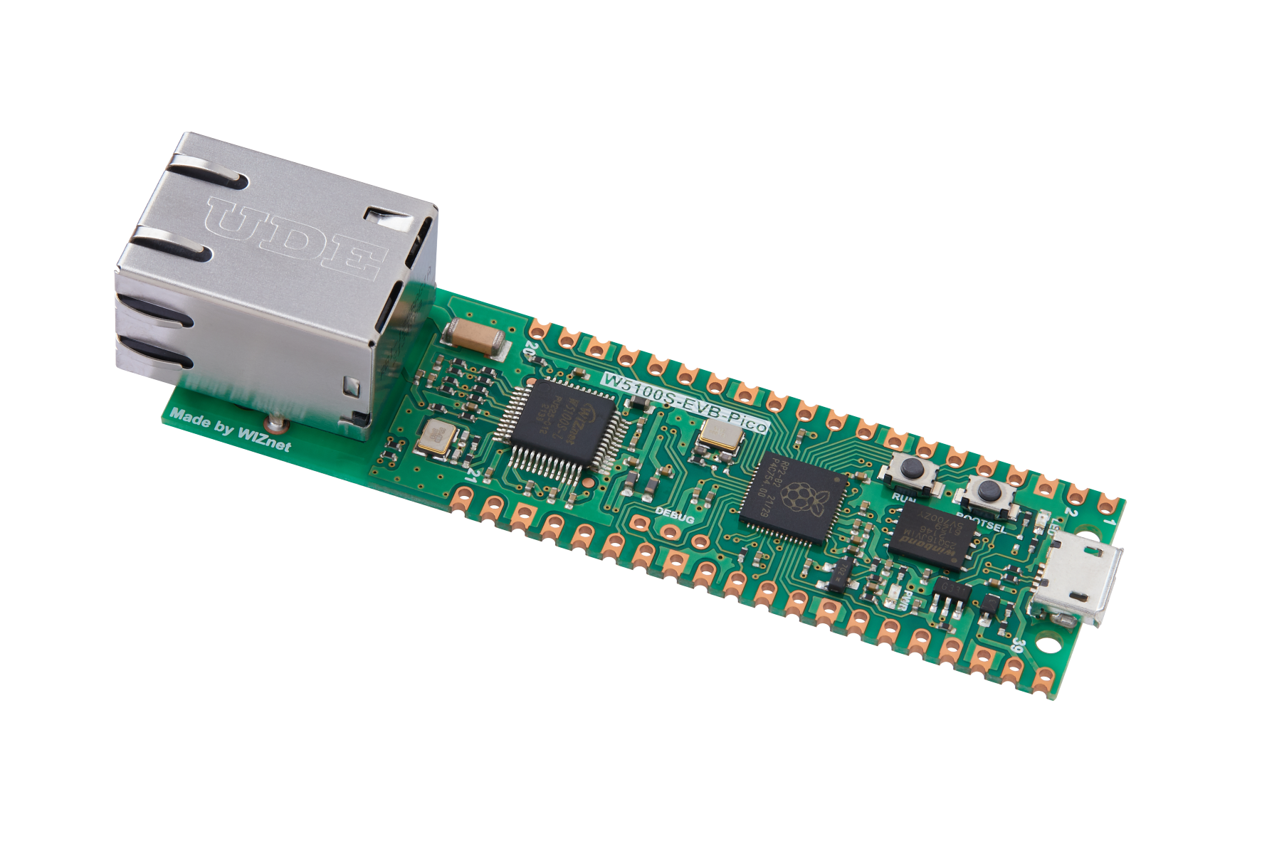
This is a application based on monitoring and controlling the battery through IOT platform Blynk Cloud. It used W5100S-EVB-PICO to work as the main communication device between the charger and Blynk.

For providing a user friendly interface, I had added Siri and shortcut feature from I-Phone to control the charger using Voice command.

All my coding methods are using circuitpython.

For details, please refer to the information below.


Structure:

Battery Charger Structure Diagram
 

This is the whole connection structure for my battery charger application.

The main feature for monitoring the battery charger is checking the voltage of the batteries.

Thus, I had used MAX471's voltage divider circuit to check voltage value.

For controlling section, I had used a relay module to control the power supply to charge the batteries.

About the communication between Blynk, It used TCP protocol.

For Blynk APP and Siri Section, It used the help with Blynk's help to make it happen.


Programming - Collect Voltage values from MAX471:

From my previous application, I had used the same library from my Solar Project.

However, I did not use the current section for this application.

MAX471 library:

import board
import analogio
import digitalio
import time

class MAX471:
    
    def __init__ (
        self, voltage_pin: pin, current_pin: pin
        ) -> None:
        self.voltage = analogio.AnalogIn(voltage_pin)
        self.current = analogio.AnalogIn(current_pin)
    
    def Voltage(self):
        """ Voltage measure  (calibrated) """
        n_result = 0
        for i in range(20):
            n_result += self.voltage.value
            #print(n_result)
            time.sleep(0.1) 
        result =(((n_result * 0.825) / 65535) * 1.0213) - 0.141
        display = ("{:.2f}").format(result)
        self.v_result = result
        return result
    
    def Current(self):
        """ Currrent measure (calibrated)"""
        n_result = 0
        for i in range(20):
            n_result += self.current.value
            #print(n_result)
            time.sleep(0.1) 
        result = (((n_result * 150) / 65535) * 1.0789) - 8.0218
        display = ("{:.2f}").format(result)
        self.c_result = result
        return display
    
    def Power(self):
        """Power = Current * Voltage"""
        result = self.c_result/1000 * self.v_result
        display = ("{:.2f}").format(result)
        return display
"""
max471 = max471(voltage_pin = board.A0, current_pin = board.A1)


while True:
    C = max471.Current()
    V = max471.Voltage()
    P = max471.Power()
"""

MAX471 Example:

import board
import busio
import digitalio
import time
import MAX471

meter = MAX471.MAX471(voltage_pin = board.A0, current_pin = board.A1)
#voltage = analogio.AnalogIn(board.A0)
while True:
    voltage = meter.Voltage()
    print (("{} V").format(voltage))
    #current = meter.Current()
    #print (("{} mA").format(current))
    #power = meter.Power()
    #print(("{} W").format(power))
    time.sleep (0.1)


Programming - Relay Control:

For relay control, it will be very simple. By using circuitpython's digitalio module, I could control one of the GPIO for the relay control.

When there is a voltage input to the relay, it could close the circuit and provide voltage to the charger.

This section will be fully controlled by Blynk.

#Add Power switch
power_switch = digitalio.DigitalInOut(board.GP0)
power_switch.direction = digitalio.Direction.OUTPUT

#Handle message from Blynk to control
@blynk.on("V5")
def v5_write_handler(value):
    if value[0] is '1':
        power_switch.value = 1
        
    elif value[0] is '0':
        power_switch.value = 0


Programming - Communicate with Blynk:

For this section, I had used Blynk library that is the same as my previous solar project.

As you may know, Blynk cloud platform is using python coding.

By combining Blynk Library and WIZnet's Circuitpython libary, I had made the full coding based for this application.

Sending Alert:

def battery_value(voltage):
    presentage = voltage /3.7 * 100
    print(presentage)
    if presentage >= 100: #check battery status
        return "full" , presentage
    elif presentage <= 0: #check is there any battery
        power_switch.value = 0
        return "no_battery", presentage
    else:
        return None, presentage

#check and send alert
msg, presentage = battery_value(voltage)
        if msg is not None:
            blynk.log_event(msg)

Sending data to Blynk:

#check the current battery switch status
def device_status():
    if power_switch.value is False:
        return '0'
    elif power_switch.value is True:
        return '1'

#Update the current battery status to Blynk
blynk.run()
status = device_status()
blynk.virtual_write(5, status) #update status

#Check the voltage value from MAX471
voltage = meter.Voltage() 
blynk.virtual_write(0, voltage) #Update the voltage of the battery
msg, presentage = battery_value(voltage) #convert to %
blynk.virtual_write(1, presentage) # Update the Battery status in %
time.sleep(1)

Full Code:

import board
import digitalio
import time
import busio
import struct
import BlynkLib
import MAX471


import adafruit_requests as requests
from adafruit_wiznet5k.adafruit_wiznet5k import * #active WIZnet chip library
import adafruit_wiznet5k.adafruit_wiznet5k_socket as socket #open socket from WIZnet library

# Go to your blynk device and input related information
BLYNK_TEMPLATE_ID = "XXXXXXXXXXXXXXX "
BLYNK_DEVICE_NAME = "Quickstart Template"
BLYNK_AUTH_TOKEN = "XXXXXXXXXXXXXXXXXXXXX"

#Add Power switch
power_switch = digitalio.DigitalInOut(board.GP0)
power_switch.direction = digitalio.Direction.OUTPUT

#Add MAX471 metering sensor
meter = MAX471.MAX471(voltage_pin = board.A0, current_pin = board.A1)

# Activate GPIO pins for SPI communication
SPI0_SCK = board.GP18
SPI0_TX = board.GP19
SPI0_RX = board.GP16
SPI0_CSn = board.GP17

# Activate Reset pin for communication with W5500 chip
W5x00_RSTn = board.GP20

print("Wiznet5k SimpleServer Test (DHCP)")

class Blynk(BlynkLib.BlynkProtocol):
    def __init__(self, auth, **kwargs):
        self.insecure = kwargs.pop('insecure', True)
        self.server = kwargs.pop('server', 'blynk.cloud')
        self.port = kwargs.pop('port', 80 if self.insecure else 443)
        BlynkLib.BlynkProtocol.__init__(self, auth, **kwargs)
        #self.on('redirect', self.redirect)
    
    def _write(self, data):
        #print('<', data)
        client.send(data) #information that we send out
        # TODO: handle disconnect
    
    def run(self):
        data = b''
        try:
            data = client.recv() #information that we received from Blynk
            #print('>', data)
        except KeyboardInterrupt:
            raise
        #except socket.timeout:
            # No data received, call process to send ping messages when needed
            #pass
        except: # TODO: handle disconnect
            return
        self.process(data)

def battery_value(voltage):
    presentage = voltage /3.7 * 100
    print(presentage)
    if presentage >= 100:
        return "full" , presentage
    elif presentage <= 0:
        power_switch.value = 0
        return "no_battery", presentage
    else:
        return None, presentage

        
def device_status():
    if power_switch.value is False:
        return '0'
    elif power_switch.value is True:
        return '1'

# Setup your network configuration below
# random MAC, later should change this value on your vendor ID
MY_MAC = (0x00, 0x08, 0xDC, 0x11, 0x22, 0x33)
IP_ADDRESS = (192, 168, 0, 111)
SUBNET_MASK = (255, 255, 0, 0)
GATEWAY_ADDRESS = (192, 168, 0, 1)
DNS_SERVER = (8, 8, 8, 8)

# Set LED for checking the network system  working
led = digitalio.DigitalInOut(board.LED)
led.direction = digitalio.Direction.OUTPUT

# Set reset function
ethernetRst = digitalio.DigitalInOut(W5x00_RSTn)
ethernetRst.direction = digitalio.Direction.OUTPUT

# Set this SPI for selecting the correct chip
cs = digitalio.DigitalInOut(SPI0_CSn)

# Set the GPIO pins for SPI communication
spi_bus = busio.SPI(SPI0_SCK, MOSI=SPI0_TX, MISO=SPI0_RX)

# Reset WIZnet's chip first
ethernetRst.value = False
time.sleep(1)
ethernetRst.value = True

# Initialize ethernet interface with DHCP
eth = WIZNET5K(spi_bus, cs, is_dhcp=True, mac=MY_MAC, debug=False)

# Show all information
print("Chip Version:", eth.chip)
print("MAC Address:", [hex(i) for i in eth.mac_address])
print("My IP address is:", eth.pretty_ip(eth.ip_address))

# Initialize steps for WIZnet's socket to create TCP server
socket.set_interface(eth)
client = socket.socket()  # Set and name the socket to be a TCP server
client_ip = "128.199.144.129"  #blynk.cloud
client_port = 80  # HTTP port for Blynk Port
client.connect((client_ip, client_port), None)

blynk = Blynk(BLYNK_AUTH_TOKEN)
@blynk.on("V5")
def v5_write_handler(value):
    if value[0] is '1':
        power_switch.value = 1
        
    elif value[0] is '0':
        power_switch.value = 0


while True:
# Maintain DHCP lease (continue the DHCP setting while TCP is connected)
    eth.maintain_dhcp_lease()

    led.value = not led.value #showing the light is blinking
    time.sleep(0.1) #transmit data speed
    

    #During the connection with Blynk Cloud, you could modified in this section.
    if client.status == SNSR_SOCK_ESTABLISHED:
        blynk.run()
        status = device_status()
        blynk.virtual_write(5, status)
        #Blynk.log_event('Device ON')
        voltage = meter.Voltage()
        blynk.virtual_write(0, voltage)
        msg, presentage = battery_value(voltage)
        if msg is not None:
            blynk.log_event(msg)
        blynk.virtual_write(1, presentage)
        time.sleep(1)

    # Found out the connection has been disconnected from the server
    elif client.status == SNSR_SOCK_CLOSE_WAIT:
        client.disconnect() #close the connection
    # Socket has closed
    elif client.status == SNSR_SOCK_CLOSED:
        client.connect((client_ip, client_port), None)


Blynk Operation - Platform setup:

As you could see from the coding, I had made some alerts setup and update through Blynk. The followings are the procedure more making it happen.

To allow me to upload information Blynk, It is required to upload information to their datastream. By having the device information from Blynk cloud and Blynk library, W5100S-EVB-PICO has the ability to communicate with those datasteam.

Thus, it is required me set datastream correctly as follow.

Datastream:


Datastream setup
Datastream setup
 

V0: Voltage datasteam to collect the acutal voltage value from W5100S-EVB-PICO

V1: Battery value that has been modified by W5100S-EVB-PICO into Persentage (%)

V5: The Power switch that controls the relay of W5100S-EVB-PICO. This feature will be actived by Blynk APP.

Alerts:

Alerts are setting the Blynk cloud to send notification on webpage and Blynk APP to allow user to be notified and take some related action.

This will be handled by "Event" section.

For this application, I had added two possiblity scenario.

1. Battery is fully charged. When the battery is fully charged (100%), it will send out a "full" command to Blynk's Log event.

2. No Battery. When the MAX471 received a value that is lower or equal than 0% of battery status, it will send out a "no_battery" commadn to Blynk's Log event.

When Blynk Cloud has received those commands, it will send out notification to my phone.

The settings will showed as follow.

Event (Alert) setup
Event (Alert) setup
 

After you had provided the information to the Blynk, you could activate those command when the condition has happend.

For details: Please refer to the Event documentation in Blynk.

No Battery Alarm:

 
No Battery Result
 
1 / 2 • No Battery Result
 

Fully Charged Alarm

Fully Charged Result


Blynk Operation - Webpage dashboard & Mobile APP dashboard

For Webpage Dashboard, the widgets from the website and Mobile APP has a slight difference. Thus, I had just added display gauge and a label bar (included value status) for the voltage and battery charging status.

For Mobile APP, It includes a button switch that allows me to easily to make my demo.

Webpage Dashboard:

Webpage Dashboard
Webpage Dashboard
 

Mobile APP dahsboard:


Mobile APP Dashboard


Siri Operation:

For Siri section, it is a very simple progress. By using Shortcut's URL get contents feature, I could easily change the settings and get information from Blynk.

By the HTTP API provided by Blynk, I could easily get information from Blynk and create notification by the following procedure.

Get datastream value from Blynk

1. Use get contents URL

2. Use HTTP API's get datastream value

3. If statement to collect message and collect the number inside the message

4. Based on your message, it will provide related information

5. Call siri and it will display the notification


Get datastream Shortcut setup
 

Get datastream Shortcut results:


Check My Charger Status


Check the Battery Status


Update datastream to Blynk

1. Use get contents URL

2. Use HTTP API's Update datastream Value

3. Call siri and it will send command to Blynk


Update datastream Shortcut


YouTube Demo:

I had made a YouTube demo based on this application. This should be a bit easy to understand with my application.


IOT Battery Charger demo


Documents

Comments

Similar projects you might like

Comments