Real Time FPGA-Based Ethernet Control Communication for Robotic Arm
Approach for real time control communication using Ethernet is proposed. The strategy to
support this at the network level and include FPGA.
3
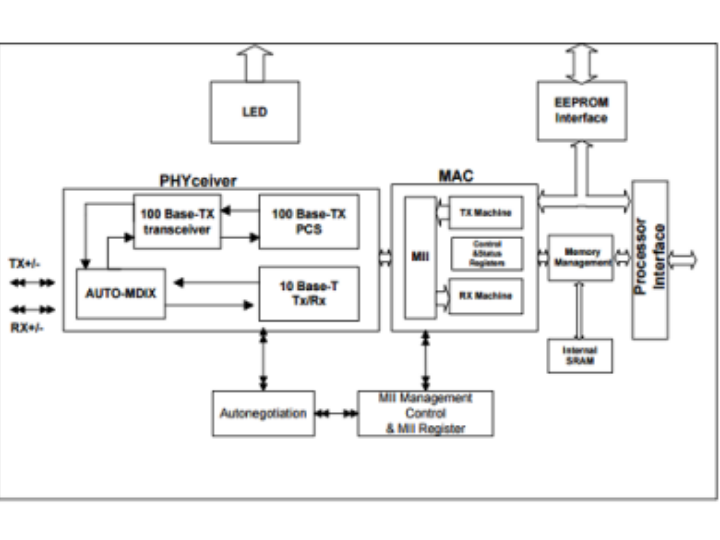
Components
Hardware components
WIZnet - W5300
x 1

Project description
Real time system is a system that produces instant output response within a specific amount of time without delay after receiving input signal [1]. It has the advantages over the non-real time system because non real time systems do not produce immediate response and do not have accountability [2]. Embedded communication network real time system is used in applications which require a set of synchronized data to be delivered in time and high response speed. Many field of application especially safety critical application use embedded communication network control to interact with real world due to flexible of designed system and less wiring complexity [3, 4]. Examples of safety critical application are military, robotics, medical, transportation system and avionics. Various types of communication control protocols which developed for network embedded real time system are used as a solution for communication problems. Altera DE2 and DE2-115 boards are used in this project as the embedded real time Ethernet controller system.
2 System design development
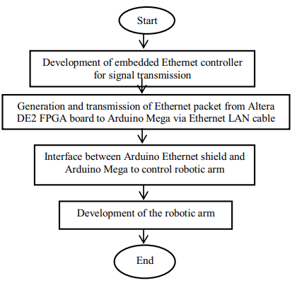
In this section, the step by step methods used to complete this project are highlighted and explained in details. The explanations are important in complete the objectives of the project. Both software and hardware are used in this project. 2.1 Development of embedded ethernet controller for signal transmission affiliations Ethernet is the main control communication protocol as this protocol is a low cost, robustness, easy to available, expendability and non-proprietary network communication solution. In order to control the Ethernet chip DM9000A in Altera DE2 FPGA board, a digital hardware system that contain components such as internal processor, RAM memory, parallel input/output interfaces, serial communication protocol, and Ethernet interface protocol will be built using SOPC builder tools in Quartus II software.
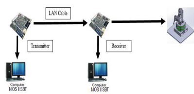
2.2 Generation and transmission of ethernet packet from altera DE2 FPGA board to arduino mega via ethernet Nios I
I processor is used to send the Ethernet packet from FPGA board to Internet by connecting Ethernet LAN cable through PHY layer via serial interface. The end point of the Ethernet packet will be stored at either server or computer. In this project, the Ethernet packet will send to the IP address of the Arduino Ethernet shield from Altera DE2 FPGA board when a push button is pressed. After this digital hardware system is created, an application program is written in C/C++ code through.
2.3 Interface between arduino ethernet shield and arduino mega to control robotic arm
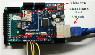
Arduino Ethernet shield is interfaced with Arduino Mega to perform control operation on robotic arm. Arduino Ethernet shield is used to enable Arduino Mega to act as the medium of communication between FPGA board and robotic arm so that signal can be transferred via (RJ45) Ethernet LAN cable. Correct IP address need to be obtained from Arduino Mega after Ethernet shield has been connected onto it.
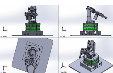
2.4 Development of the robotic arm Robotic arm with 3 degree of freedom and the end effector is a gripper is designed by using of SolidWorks software and simulated with MATLAB software. The robotic arm is capable of doing the task of pick and place of objects. All 3 links and joints are revolute. This robot is configured as an articulated robot. Estimation is being made for design material specification, theory to calculate the torque of the robotic arm is applied and its relationship towards rotational speed. Servo motor is a rotary actuator that allows for precise control of angular position [9]. In this project, type of analog servo motors HD-1501MG are used. Servo motor is the most suitable motor in this project because it is low cost and has a lot of advantage compared to the other motor such as stepper motor, brushless motor, ac motor, etc. The robotic arm is printed with 3D printer so that precise dimension guaranteed. Servo motors are used on the robotic arm. By using SolidWorks software, the robotic arm is designed. After designing, simulation process must be carried out to make sure there is zero interference and to test on the robotic arm joints and links feasibility as in real world [10].
2.5 Development of real-time communication system between two FPGA devices In this digital hardware system, Triple Speed Ethernet MegaCore is chosen as the Ethernet Controller instead of DM9000A. This is because the FPGA boards use to build this communication system is DE2-115 series and the Ethernet PHY chip (Marvell 8E1111) of this board can only support this Ethernet controller. Besides, a timer will be used to determine the transmission time and reception time of Ethernet packets at transmitter and receiver. This timer is implemented by using a 32-bit counter and its timing behavior is based on the internal clock frequency of DE2-115 FPGA board.
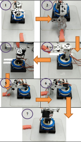
3 Results and discussion The Altera DE2 FPGA board transmits Ethernet data packet of different sizes to the Arduino Mega. If the data packet of greater or equal to 1200 bytes is received by the Arduino Ethernet shield, the Arduino Mega will perform control operation of pick and place object on two points. The object to be picked up is a sponge.The combine (Front, Left, Top and Trimetric) view of the robotic arm is shown in Figure 5.
For the communication setup which used FPGA and Arduino board, the average transmission delay of each data packet is 16ms. From the data measurements, transmission delay of each data packet can be calculated by using the formula:
4 Conclusion In conclusion, the control communication is successfully developed at high data transfer for real-time control communication to communicate with other controller device for robotic arm with Arduino board and FPGA board via Ethernet. Through this implementation, the ability to communicate safety data directly over an Ethernet/IP network is achieved. The practical test results have shown that the delay is reduced by 93.3% after the receiver in a communication system is changed from Arduino board to FPGA board

