Ethernet controller W5300. Initialization. ping
Today is more interesting. We will try to initialize the W5300 and ping.
4
Components
Hardware components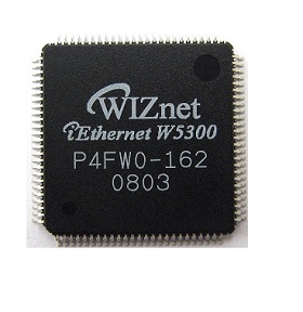
WIZnet - W5300
x 1

Project description
Original link is https://blog.radiotech.kz/stm32/ethernet-kontroller-w5300-initsializatsiya-ping/
and posted in the Czech language.
What we need for this:
- a board with W5300 (own-made or ready-made, for example WIZ830MJ);
- control module (I have a STM32F4-Discovery handkerchief);
- development environment, debugger, compiler, depending on what you have chosen as a control module. (I have Keil. They have a free version with a code limit of up to 32 KB. Personally, this is more than enough for me. :-))) );
- sniffer. This item is not required, but we will need it later. Sniffer - a program that will show us packets on the network. I like WireShark. By the way, during the installation, WireShark will ask permission to install WinPcap. Agree. If WinPcap does not ask you to install it, then you will have to install it separately.
Scheme
We access the W5300 memory using direct addressing and a 16-bit data bus. I will not draw a schematic diagram, I will simply describe which GPIOs go to which legs of the WIZ830MJ.
WIZ830MJ STM32F4-Discovery
Address bus ADDR [0:9] GPIOE [0:9]
Data bus DATA [0:15] GPIOD [0:15]
CS GPIOB 13
RD GPIOB 14
WR GPIOB 15
RES GPIOB 11
Create a project in Keil
I will describe how to create a project in Keil, in case this may cause difficulties.
Project -> New uVision Project
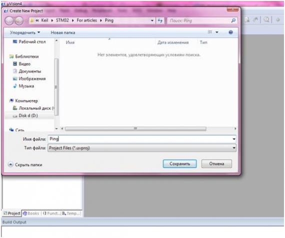
Choosing our microcontroller:
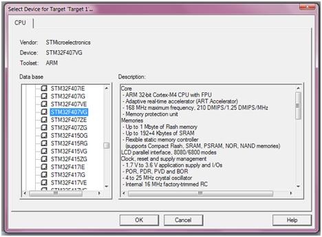
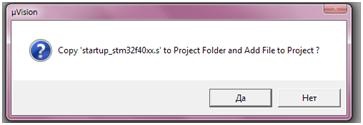
We agree to copy the startup file:
Copy the CMSIS folder to the project folder, which in turn contains the files:
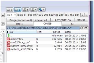
These files can be taken from STM32CubeF4
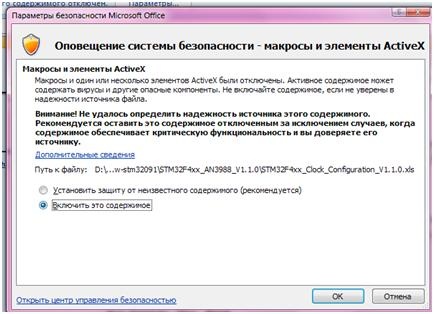
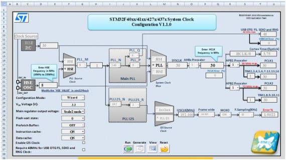
And the system_stm32f4xx.c file is generated using the STM32F4xx_Clock_Configuration Excel file . Download, unpack and run the Excel file (UPD at the time of writing this was the easiest way to set up clocking, now it is recommended to use the CubeMX code generator).
Activate the macro by clicking the Options button.
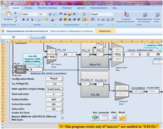
We set the frequency value at the output and at the input, press the Run button, in the process we select the external HSE clock source. Next, click Generate and in the same folder in which the Excel file is located, we find system_stm32f4xx.c, generated for our frequency and for our divisor coefficients.
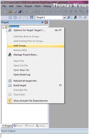
Adding a CMSIS group to our project:
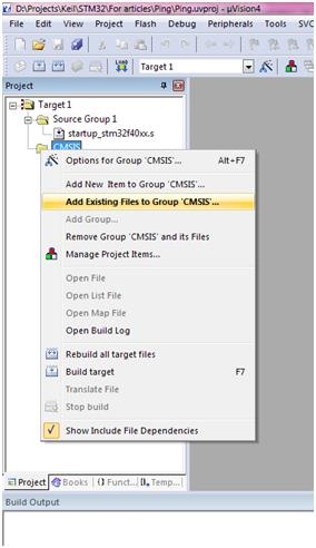
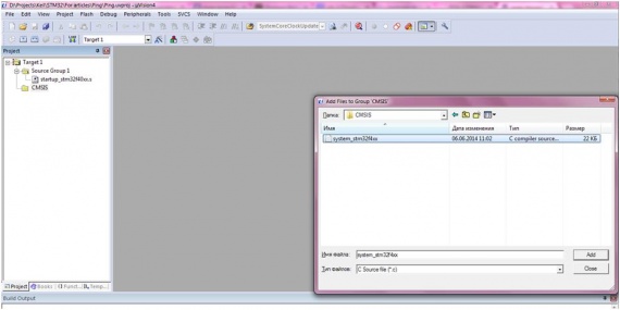
Add a sish file from the CMSIS folder to the CMSIS group:
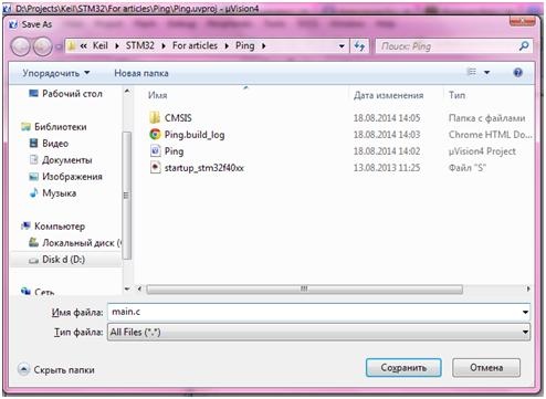
Now we create a new file, when saving we call it main.c.
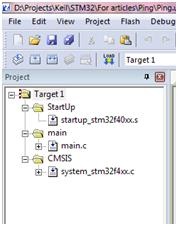
Create a main group, add the file we just created to it.
The project structure should now look like this:
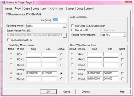
Immediately in the project options, we make the following changes.
We set the frequency to 30 MHz:
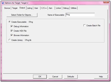
Set the Create HEX checkbox, otherwise we will not be able to flash.
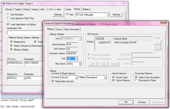
Select the ST-Link debugger, Settings -> Debug Port should be SW.
Define
Further, already in the program, we prescribe the addresses of the registers of the ethernet controller, someone does it in the header, someone in the main file, more correctly, of course, in the header.
In general, we look in the datasheet for the W5300, where the addresses of the registers are written on pages 25 - 44. For now, we only need these registers:
STM32F407 initialization
W5300 Write, Read Register Functions
The datasheet contains the following diagram explaining to us the process of writing to the W5300 registers:
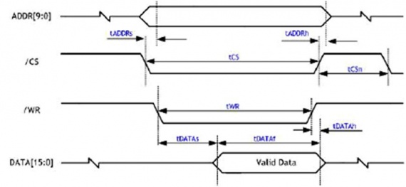
In accordance with it, we write the code:
Exactly the same diagram is given for reading from registers.
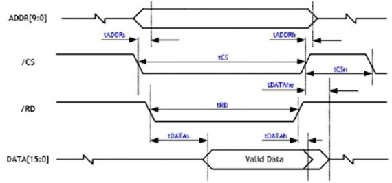
Here I think, nothing complicated.
Delay function
W5300 initialization and reset signal
What should be the duration of the reset signal is also indicated in the datasheet:
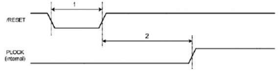
Next ... We write down the MAC address, IP address, subnet mask of our device, IP address of the main gateway:
Compiling, flashing.
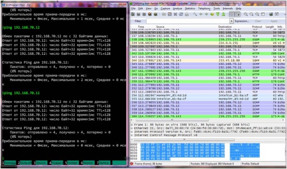
ping
Ping went and our ICMP packets too!