hkdt_pico
Pico SDK robot library for W6300-EVB-Pico2: a non-blocking W6300 UDP socket API alongside RoboMaster CAN motor, PID and WS2812 drivers.
0
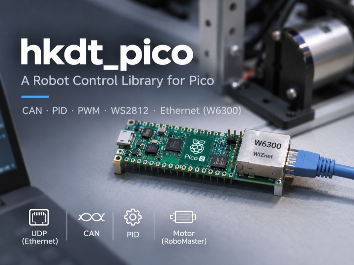
Components
Hardware components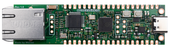
WIZnet - W6300-EVB-Pico2
x 1

Project description
Overview
hkdt_pico is a general-purpose Pico SDK library for robot control boards, built on the W6300-EVB-Pico2 (RP2350 + WIZnet W6300). One CMake target bundles the pieces a small robot controller usually needs: CAN bus, RoboMaster motor feedback, PID control, PWM, WS2812 status LEDs and wired Ethernet. The Ethernet part is just four UDP functions (initialize, receive, send, close, inc/w6300_ethernet.h), and the W6300 handles UDP/IP itself through WIZnet's ioLibrary socket API, so the RP2350 keeps its time for the motor loop.
It fits robots where a PC or single-board computer makes the decisions and a microcontroller drives the motors: the PC sends targets over a cable, and the Pico2 runs PID and talks CAN to RoboMaster motors. The same board also works as a motor test bench that streams feedback to a PC while you tune gains, or as a wired operator link that stays out of a crowded 2.4 GHz band. The library is by motii (@motii8128, hkdt_pico); the repository was created on 2026-08-29, last pushed on 2026-10-30, and has no license file.
At a Glance
| Item | What the source shows |
|---|---|
| Purpose | General-purpose Pico SDK library ("汎用ライブラリ", repository description) |
| Ethernet chip | WIZnet W6300 (src/w6300_ethernet.c, CMakeLists.txt:14) |
| Board target | W6300_EVB_PICO2 (inc/wizchip/wizchip_spi.h:13) |
| Host interface | PIO QSPI driver, pins GPIO15 to GPIO22 (inc/wizchip/wizchip_spi.h:39-46) |
| Network protocol | UDP over IPv4, static address (src/w6300_ethernet.c:41, :62) |
| Other modules | CAN (can2040), RoboMaster parser, PID/cascade PID, PWM, WS2812 |
| Examples | Two, both inside README.md: RoboMaster over CAN, W6300 UDP |
| License | No license file in the repository |
Why Is It Worth a Look?
Most W6300 examples show the chip on its own. hkdt_pico shows the W6300 as one part of a robot controller, sitting next to a CAN motor bus and a PID controller in the same library. That is the situation a robot builder actually faces.
The network API is small on purpose. initialize_w6300_ethernet() takes a socket number, IP, gateway and port, and returns the socket number on success (inc/w6300_ethernet.h:16). Behind that one call sit SPI/QSPI setup, chip reset, a chip-ID check, network configuration and UDP socket creation (src/w6300_ethernet.c:51-62). A builder who only wants "send this struct to the PC" does not need to learn the ioLibrary first.
The receive call does not block when nothing has arrived. recv_w6300_udp() first asks the chip how many bytes are waiting (getsockopt(..., SO_RECVBUF, ...), src/w6300_ethernet.c:69) and returns -1 at once if the answer is zero (:90-93). That matters for a robot: a control loop can poll the network every pass without stalling the motor update.
The project is also being used and fixed. The commit history shows the W6300 library added on 2026-09-14 (commit 3b42392), a UDP example the same day (17ed83e), and a fix on 2026-10-30 whose message says it is an update made after an operation check (0d2ebf8, "動作確認にともなうアップデート"). That last commit changed the receive length passed to recvfrom() from size - 1 to size.
How Does It Work?
 PC / ROS host / another robot (UDP, port set by user)
            |
        Ethernet cable
            |
   +------------------+   UDP/IP, ARP, socket buffers
   |   WIZnet W6300   |   handled inside the chip
   +------------------+
            |  PIO QSPI: CS=16, SCK=17, IO0-IO3=18-21,
            |            INT=15, RST=22 (wizchip_spi.h:39-46)
   +------------------+
   |  RP2350 (Pico2)  |  main loop:
   |                  |   - recv_w6300_udp()  (returns -1 if empty)
   |                  |   - can_receive()     (queue, PIO0 IRQ)
   |                  |   - PID / cascade PID
   |                  |   - can_transmit()    every 20 ms (README)
   +------------------+
            |  CAN via can2040 on PIO0, TX=GPIO7 RX=GPIO6 in README
   +------------------+
   | CAN transceiver  | --> RoboMaster motors (ID 0x200 frame)
   +------------------+
The CAN pins, the 1 Mbps rate and the 20 ms send period come from the README example (README.md:36, :61). The W6300 pins come from the board header. Both run in one for(;;) loop in the README examples; the library has no RTOS or task layer.
What W6300 Actually Does
The W6300 runs the network stack in hardware. The code uses WIZnet's ioLibrary socket calls: socket(socket_num, Sn_MR_UDP, my_port, 0) (src/w6300_ethernet.c:62), recvfrom() (:79), sendto() (:99), and disconnect()/close() (:104-105). With this API the chip builds and parses UDP/IP packets and answers ARP; the RP2350 only moves payload bytes over QSPI. There is no lwIP and no MACRAW mode anywhere in the repository.
The library initializes 4 KB of TX and 4 KB of RX buffer for each of the W6300's eight sockets (src/wizchip/wizchip_spi.c:281). The wrapper itself opens one UDP socket per call.
What the W6300 does not do here: there is no TCP wrapper, no DHCP, and no IPv6 traffic. The IPv6 fields in wiz_NetInfo are filled in, but the socket is opened as plain UDP and sendto() is called with a 4-byte address (src/w6300_ethernet.c:99). The W6300 also does not touch the CAN bus or the motors; those run entirely on the RP2350's PIO0 through can2040 (src/can.c:5-19).
How Is the W6300 Connected, and Is It Really Running Quad?
The board header selects W6300_EVB_PICO2 and enables the PIO driver with all four data lines wired: IO0 to IO3 on GPIO18 to GPIO21 (inc/wizchip/wizchip_spi.h:13, :35, :42-45). The PIO clock divider is 2.0 (:36-37), and the driver prints the resulting clock at start-up as sys_clk / (2 × divider) (src/wizchip/wizchip_qspi_pio.c:229-233). The repository does not set the system clock, so the actual QSPI clock depends on the SDK default and is not stated in the source.
The number of data lines actually used is a separate setting. The PIO driver picks a single, dual or quad program from _WIZCHIP_QSPI_MODE_ (src/wizchip/wizchip_qspi_pio.c:28-34). In the ioLibrary commit this repository pins as a submodule (39fae86), that macro defaults to QSPI_SINGLE_MODE (Ethernet/wizchip_conf.h:277-279), and nothing in hkdt_pico overrides it. So a build made exactly as the README describes talks to the W6300 over one data line, with the four-line wiring ready for later. Switching to quad mode is a build-flag change, not a hardware change.
The driver prefers PIO1 for the W6300 and falls back to PIO0 if PIO1 is full (src/wizchip/wizchip_qspi_pio.c:21-22, :199-206). CAN is fixed on PIO0 (src/can.c:5), which keeps the two apart by default.
How Does UDP Fit a Robot Control Loop?
The README's CAN example shows the timing style the library expects. It sends a motor current frame every 20 ms using delayed_by_us() so the period does not drift, and reads CAN frames whenever they are queued (README.md:46-89). Received frames go into a 128-entry queue filled by the PIO interrupt (inc/can.h:13, :29-44).
UDP slots into the same loop. Because recv_w6300_udp() returns immediately when nothing is waiting, a host PC can send set-points over Ethernet while the RP2350 keeps the 20 ms CAN rhythm. The RoboMaster parser turns each feedback frame into velocity, torque, temperature and a multi-turn position, unwrapping the 8192-count encoder at the ±4096 boundary (src/robomaster.c:18-43). Those values are what a builder would most likely send back over UDP for logging or a host-side controller.
The library does not include such a combined example. The two README examples are separate programs, and joining them is left to the builder.
Where Could You Use It?
- Robot base controller with a PC brain. A laptop or SBC sends wheel or arm targets over UDP; the Pico2 runs PID and drives RoboMaster motors over CAN.
- Motor test bench. Stream RoboMaster velocity and position feedback to a PC over a cable for plotting while tuning PID gains.
- Competition robot with a wired operator link. A wired UDP link instead of a shared 2.4 GHz band, with WS2812 LEDs on the same board for status.
- Multi-board robot. Several Pico2 boards on one switch, each handling one subsystem and reporting over UDP (each needs its own MAC address, see below).
Engineering Value and Source Limits
The value is a compact, readable bridge between three things a robot builder needs at once: a hardware network stack on the W6300, a software CAN bus on PIO, and motor feedback parsing. The W6300 part is short enough to read in a few minutes (src/w6300_ethernet.c, 106 lines).
Check these before use:
- License. The repository has no license file. The WIZnet and Raspberry Pi port files inside it carry BSD-3-Clause headers (
inc/wizchip/wizchip_spi.h:1-5,inc/wizchip/wizchip_qspi_pio.h:1-5), but the author's own code has no stated terms. Ask the author before reusing it. - Fixed MAC and subnet. Every board uses MAC
00:08:DC:12:34:56and mask255.255.255.0(src/w6300_ethernet.c:6,:8). Two boards on one network need different MAC addresses. - Start-up waits for the cable. Initialization loops until the PHY reports link up (
src/wizchip/wizchip_spi.c:293-300), and stops forever if the chip ID is not0x6300(:330-334). Bring the network up before motors are enabled. - QSPI lane mode. As built, single-line mode (see above). Quad is not shown or measured in the repository.
- PIO sharing. The WS2812 helper always uses state machine 0 without claiming it (
src/ws2812.c:18). If you put WS2812 on PIO1 next to the W6300, check which state machine each one gets. - README UDP example. The example loop sends the 128-byte buffer on every pass even when nothing was received (
README.md:120-139). Gate the send on a successful receive in real code. - Not in the source. No throughput or latency numbers, no photos or schematics of the robot, no combined CAN + UDP example, no tests. The README and comments are in Japanese.
Related WIZnet Maker Reading Path
- STM32F103 + W5500 UDP-to-CANopen Gateway for a ZLAC8015D Dual-Motor Robot: the same "UDP from host, CAN to motors" idea on a different MCU and chip.
- Bringing WIZnet W6300 QSPI Ethernet to Propeller 2: W6300 QSPI pin planning on another host.
- How to Wake a PC with Wake-on-LAN from a W6300-EVB-Pico: another small W6300 UDP sender.
- How to Connect MELSEC PLCs with Binary SLMP 3E/4E on W6300-EVB-Pico2?: the same board used for an industrial protocol.
Source-Backed Summary
- hkdt_pico is a Pico SDK robot library with CAN, RoboMaster parsing, PID, PWM, WS2812 and W6300 UDP in one CMake target (
CMakeLists.txt:1-21). - The W6300 handles UDP/IP through the ioLibrary socket API (
src/w6300_ethernet.c:62,:79,:99); no lwIP or MACRAW is used. - The target board is W6300-EVB-Pico2 with a PIO QSPI link on GPIO15 to GPIO22 (
inc/wizchip/wizchip_spi.h:13,:39-46). - Four data lines are wired, but the pinned ioLibrary defaults to single-line mode (
wizchip_conf.h:277-279). - UDP receive is non-blocking, which fits a fixed-period motor loop (
src/w6300_ethernet.c:69-93). - Development stage: working library with README examples, actively fixed through 2026-10-30, no license, no measurements.
FAQ
Does the RP2350 run a TCP/IP stack in this project?
No. The W6300 builds and parses the UDP/IP packets itself. The RP2350 calls socket(), sendto() and recvfrom() from WIZnet's ioLibrary and only moves the payload bytes.
Is the W6300 running in quad SPI mode?
Not by default. All four data lines are wired (GPIO18 to GPIO21), but the pinned ioLibrary sets single-line mode unless _WIZCHIP_QSPI_MODE_ is defined as QSPI_QUAD_MODE at build time.
Can I use TCP instead of UDP?
Not through this wrapper. It only opens UDP sockets. The ioLibrary underneath supports TCP, so you could add your own wrapper.
Will it work on a W5500 or the older W6300-EVB-Pico?
The port header lists other boards (inc/wizchip/board_list.h), but DEVICE_BOARD_NAME is hard-coded to W6300_EVB_PICO2 and the CMake file builds only the W6300 driver. Other boards are untested in this repository.
Can I copy this into my own robot?
The repository has no license file, so the author's code has no stated terms. Ask the author first.
W6300-EVB-Pico2 로봇 라이브러리는 어떻게 네트워크 함수 4개만으로 RoboMaster CAN 모터 옆에서 UDP를 돌리는가?
개요
hkdt_pico는 W6300-EVB-Pico2(RP2350 + WIZnet W6300)를 기반으로 한 로봇 제어 보드용 범용 Pico SDK 라이브러리다. 작은 로봇 컨트롤러에 보통 필요한 CAN 버스, RoboMaster 모터 피드백, PID 제어, PWM, WS2812 상태 LED, 유선 이더넷을 CMake 타깃 하나로 묶었다. 이더넷 부분은 UDP 함수 네 개(초기화·수신·송신·종료, inc/w6300_ethernet.h)가 전부이고, W6300이 WIZnet ioLibrary 소켓 API로 UDP/IP 처리를 칩 안에서 직접 하므로 RP2350은 모터 루프에 시간을 쓸 수 있다.
PC나 SBC가 판단을 맡고 MCU가 모터를 돌리는 로봇에 잘 맞는다. PC가 케이블로 목표값을 보내면 Pico2가 PID를 돌려 CAN으로 RoboMaster 모터를 구동한다. 같은 보드를 PID 게인을 맞추는 동안 피드백을 PC로 흘려보내는 모터 시험대로 쓰거나, 붐비는 2.4 GHz 대역을 피하는 유선 조종 링크로 쓸 수도 있다. 작성자는 motii(@motii8128, hkdt_pico)이고, 저장소는 2026-08-29 생성, 마지막 푸시는 2026-10-30이며 라이선스 파일이 없다.
한눈에 보기
| 항목 | 소스에서 확인되는 것 |
|---|---|
| 목적 | Pico SDK용 범용 라이브러리("汎用ライブラリ", 저장소 설명) |
| 이더넷 칩 | WIZnet W6300 (src/w6300_ethernet.c, CMakeLists.txt:14) |
| 대상 보드 | W6300_EVB_PICO2 (inc/wizchip/wizchip_spi.h:13) |
| 호스트 연결 | PIO QSPI 드라이버, GPIO15~GPIO22 (inc/wizchip/wizchip_spi.h:39-46) |
| 네트워크 프로토콜 | IPv4 UDP, 고정 주소 (src/w6300_ethernet.c:41, :62) |
| 다른 모듈 | CAN(can2040), RoboMaster 파서, PID/캐스케이드 PID, PWM, WS2812 |
| 예제 | README.md 안에 두 개: CAN으로 RoboMaster 제어, W6300 UDP |
| 라이선스 | 저장소에 라이선스 파일 없음 |
왜 눈여겨볼 만한가?
W6300 예제는 대부분 칩 하나만 보여준다. hkdt_pico는 W6300을 로봇 컨트롤러의 한 부품으로 보여준다. 같은 라이브러리 안에서 CAN 모터 버스, PID 제어기와 나란히 놓인다. 로봇을 만드는 사람이 실제로 마주하는 상황이 이 구성이다.
네트워크 API는 일부러 작게 만들었다. initialize_w6300_ethernet()은 소켓 번호, IP, 게이트웨이, 포트를 받고 성공하면 소켓 번호를 돌려준다(inc/w6300_ethernet.h:16). 이 호출 하나 뒤에서 SPI/QSPI 설정, 칩 리셋, 칩 ID 확인, 네트워크 설정, UDP 소켓 생성이 차례로 일어난다(src/w6300_ethernet.c:51-62). "이 구조체를 PC로 보내기"만 원하는 사람은 ioLibrary를 먼저 공부할 필요가 없다.
수신 함수는 받은 데이터가 없을 때 멈추지 않는다. recv_w6300_udp()는 먼저 칩에 대기 중인 바이트 수를 묻고(getsockopt(..., SO_RECVBUF, ...), src/w6300_ethernet.c:69), 0이면 바로 -1을 돌려준다(:90-93). 로봇에서는 이 점이 중요하다. 제어 루프가 매 회차 네트워크를 확인해도 모터 갱신이 밀리지 않는다.
실제로 쓰면서 고치고 있는 프로젝트이기도 하다. 커밋 기록을 보면 2026-09-14에 W6300 라이브러리가 추가됐고(3b42392), 같은 날 UDP 예제가 들어갔다(17ed83e). 2026-10-30 커밋(0d2ebf8)의 메시지는 "동작 확인에 따른 업데이트"(動作確認にともなうアップデート)다. 이 커밋은 recvfrom()에 넘기는 수신 길이를 size - 1에서 size로 바꿨다.
어떻게 동작하는가?
 PC / ROS 호스트 / 다른 로봇 (UDP, 포트는 사용자가 지정)
            |
        이더넷 케이블
            |
   +------------------+   UDP/IP, ARP, 소켓 버퍼를
   |   WIZnet W6300   |   칩 안에서 처리
   +------------------+
            |  PIO QSPI: CS=16, SCK=17, IO0-IO3=18-21,
            |            INT=15, RST=22 (wizchip_spi.h:39-46)
   +------------------+
   |  RP2350 (Pico2)  |  메인 루프:
   |                  |   - recv_w6300_udp()  (비어 있으면 -1)
   |                  |   - can_receive()     (큐, PIO0 인터럽트)
   |                  |   - PID / 캐스케이드 PID
   |                  |   - can_transmit()    20 ms마다 (README)
   +------------------+
            |  can2040으로 PIO0에서 CAN, README 기준 TX=GPIO7 RX=GPIO6
   +------------------+
   | CAN 트랜시버      | --> RoboMaster 모터 (ID 0x200 프레임)
   +------------------+
CAN 핀, 1 Mbps 속도, 20 ms 송신 주기는 README 예제에서 온 값이다(README.md:36, :61). W6300 핀은 보드 헤더에서 온 값이다. README 예제에서는 둘 다 for(;;) 루프 하나에서 돈다. 라이브러리에 RTOS나 태스크 계층은 없다.
W6300이 실제로 하는 일
W6300은 네트워크 스택을 하드웨어로 처리한다. 코드는 WIZnet ioLibrary 소켓 호출을 쓴다. socket(socket_num, Sn_MR_UDP, my_port, 0)(src/w6300_ethernet.c:62), recvfrom()(:79), sendto()(:99), disconnect()/close()(:104-105)다. 이 API를 쓰면 UDP/IP 패킷을 만들고 해석하고 ARP에 응답하는 일은 칩이 한다. RP2350은 QSPI로 데이터 바이트만 옮긴다. 저장소 어디에도 lwIP나 MACRAW 모드는 없다.
라이브러리는 W6300의 소켓 8개 각각에 송신 4 KB, 수신 4 KB 버퍼를 잡는다(src/wizchip/wizchip_spi.c:281). 래퍼 자체는 호출 한 번에 UDP 소켓 하나를 연다.
여기서 W6300이 하지 않는 일도 있다. TCP 래퍼, DHCP, IPv6 통신은 없다. wiz_NetInfo에 IPv6 필드가 채워져 있지만, 소켓은 일반 UDP로 열리고 sendto()는 4바이트 주소로 호출된다(src/w6300_ethernet.c:99). W6300은 CAN 버스나 모터에도 관여하지 않는다. CAN은 can2040을 통해 RP2350의 PIO0에서 전부 처리된다(src/can.c:5-19).
W6300은 어떻게 연결되고, 정말 쿼드로 동작하는가?
보드 헤더는 W6300_EVB_PICO2를 선택하고 PIO 드라이버를 켠다. 데이터선 4개가 모두 배선돼 있다. IO0~IO3이 GPIO18~GPIO21이다(inc/wizchip/wizchip_spi.h:13, :35, :42-45). PIO 클럭 분주비는 2.0이고(:36-37), 드라이버는 부팅 시 실제 클럭을 sys_clk / (2 × 분주비)로 계산해 출력한다(src/wizchip/wizchip_qspi_pio.c:229-233). 저장소가 시스템 클럭을 따로 설정하지 않으므로 실제 QSPI 클럭은 SDK 기본값에 따라 정해지고, 소스에 수치로 적혀 있지는 않다.
실제로 쓰는 데이터선 수는 별도 설정이다. PIO 드라이버는 _WIZCHIP_QSPI_MODE_ 값에 따라 싱글·듀얼·쿼드 프로그램 중 하나를 고른다(src/wizchip/wizchip_qspi_pio.c:28-34). 이 저장소가 서브모듈로 고정한 ioLibrary 커밋(39fae86)에서는 이 매크로의 기본값이 QSPI_SINGLE_MODE이고(Ethernet/wizchip_conf.h:277-279), hkdt_pico 안에는 이 값을 바꾸는 곳이 없다. 따라서 README대로 빌드하면 W6300과 데이터선 하나로 통신하고, 4선 배선은 나중을 위해 준비된 상태다. 쿼드 모드로 바꾸는 것은 하드웨어가 아니라 빌드 플래그 변경이다.
드라이버는 W6300에 PIO1을 먼저 쓰고, PIO1이 꽉 차 있으면 PIO0으로 넘어간다(src/wizchip/wizchip_qspi_pio.c:21-22, :199-206). CAN은 PIO0에 고정이라(src/can.c:5) 기본 상태에서는 둘이 겹치지 않는다.
UDP는 로봇 제어 루프에 어떻게 들어가는가?
README의 CAN 예제가 이 라이브러리가 기대하는 타이밍 방식을 보여준다. delayed_by_us()로 주기가 밀리지 않게 하면서 20 ms마다 모터 전류 프레임을 보내고, 큐에 들어온 CAN 프레임은 그때그때 읽는다(README.md:46-89). 수신 프레임은 PIO 인터럽트가 채우는 128칸 큐에 쌓인다(inc/can.h:13, :29-44).
UDP도 같은 루프에 들어간다. recv_w6300_udp()는 기다리는 데이터가 없으면 바로 돌아오므로, 호스트 PC가 이더넷으로 목표값을 보내는 동안에도 RP2350은 20 ms CAN 주기를 유지할 수 있다. RoboMaster 파서는 피드백 프레임마다 속도, 토크, 온도, 다회전 위치를 뽑는다. 8192카운트 엔코더 값이 ±4096 경계를 넘을 때 감김을 풀어 위치를 누적한다(src/robomaster.c:18-43). UDP로 다시 보내 로그를 남기거나 호스트 쪽 제어기에 넘길 값이 바로 이것들이다.
다만 두 기능을 합친 예제는 라이브러리에 없다. README의 두 예제는 각각 별도 프로그램이고, 합치는 일은 사용자 몫이다.
이런 곳에 사용할 수 있다
- PC를 두뇌로 쓰는 로봇 베이스 컨트롤러. 노트북이나 SBC가 UDP로 바퀴·팔 목표값을 보내고, Pico2가 PID를 돌려 CAN으로 RoboMaster 모터를 구동한다.
- 모터 시험대. PID 게인을 맞추는 동안 RoboMaster 속도·위치 피드백을 케이블로 PC에 흘려 그래프로 본다.
- 유선 조종 링크를 쓰는 대회 로봇. 여러 팀이 공유하는 2.4 GHz 대역 대신 유선 UDP를 쓰고, 같은 보드의 WS2812 LED로 상태를 표시한다.
- 보드 여러 장으로 나눈 로봇. Pico2 여러 장을 스위치 하나에 물리고, 각 보드가 하위 시스템 하나씩 맡아 UDP로 보고한다(보드마다 MAC 주소를 달리해야 한다, 아래 참고).
엔지니어링 가치와 소스의 한계
가치는 로봇 제작자가 동시에 필요로 하는 세 가지를 작고 읽기 쉽게 이어 준다는 데 있다. W6300의 하드웨어 네트워크 스택, PIO 기반 소프트웨어 CAN 버스, 모터 피드백 파싱이다. W6300 부분은 몇 분이면 다 읽을 만큼 짧다(src/w6300_ethernet.c, 106줄).
사용 전에 확인할 점:
- 라이선스. 저장소에 라이선스 파일이 없다. 안에 포함된 WIZnet·Raspberry Pi 포트 파일에는 BSD-3-Clause 헤더가 있지만(
inc/wizchip/wizchip_spi.h:1-5,inc/wizchip/wizchip_qspi_pio.h:1-5), 작성자 본인 코드에는 사용 조건이 적혀 있지 않다. 재사용 전에 작성자에게 문의한다. - 고정 MAC과 서브넷. 모든 보드가 MAC
00:08:DC:12:34:56, 마스크255.255.255.0을 쓴다(src/w6300_ethernet.c:6,:8). 한 네트워크에 보드 두 장을 물리려면 MAC 주소를 달리해야 한다. - 부팅이 케이블 연결을 기다린다. 초기화는 PHY 링크가 올라올 때까지 반복하고(
src/wizchip/wizchip_spi.c:293-300), 칩 ID가0x6300이 아니면 영원히 멈춘다(:330-334). 모터를 켜기 전에 네트워크를 먼저 올린다. - QSPI 데이터선 모드. 그대로 빌드하면 싱글 모드다(위 참고). 쿼드 모드는 저장소에서 사용되거나 측정되지 않았다.
- PIO 공유. WS2812 헬퍼는 상태 머신 0번을 점유 확인 없이 항상 쓴다(
src/ws2812.c:18). WS2812를 W6300과 같은 PIO1에 두면 각자 어떤 상태 머신을 쓰는지 확인한다. - README UDP 예제. 예제 루프는 아무것도 받지 못해도 매 회차 128바이트 버퍼를 보낸다(
README.md:120-139). 실제 코드에서는 수신 성공일 때만 보내도록 바꾼다. - 소스에 없는 것. 처리량·지연 수치, 로봇 사진이나 회로도, CAN+UDP 통합 예제, 테스트가 없다. README와 주석은 일본어다.
관련 WIZnet Maker 읽을거리
- STM32F103 + W5500 UDP-to-CANopen Gateway for a ZLAC8015D Dual-Motor Robot: 다른 MCU와 칩으로 같은 "호스트에서 UDP, 모터로 CAN" 구조를 구현한 글.
- Bringing WIZnet W6300 QSPI Ethernet to Propeller 2: 다른 호스트에서의 W6300 QSPI 핀 배치.
- How to Wake a PC with Wake-on-LAN from a W6300-EVB-Pico: 또 하나의 작은 W6300 UDP 송신기.
- How to Connect MELSEC PLCs with Binary SLMP 3E/4E on W6300-EVB-Pico2?: 같은 보드를 산업용 프로토콜에 쓴 사례.
소스 근거 요약
- hkdt_pico는 CAN, RoboMaster 파싱, PID, PWM, WS2812, W6300 UDP를 CMake 타깃 하나에 묶은 Pico SDK 로봇 라이브러리다(
CMakeLists.txt:1-21). - W6300이 ioLibrary 소켓 API로 UDP/IP를 처리한다(
src/w6300_ethernet.c:62,:79,:99). lwIP나 MACRAW는 쓰지 않는다. - 대상 보드는 W6300-EVB-Pico2이고 GPIO15~GPIO22의 PIO QSPI로 연결된다(
inc/wizchip/wizchip_spi.h:13,:39-46). - 데이터선 4개가 배선돼 있지만, 고정된 ioLibrary의 기본값은 싱글 모드다(
wizchip_conf.h:277-279). - UDP 수신이 멈추지 않으므로 고정 주기 모터 루프에 맞는다(
src/w6300_ethernet.c:69-93). - 개발 단계: README 예제가 있는 동작 라이브러리, 2026-10-30까지 수정이 이어짐, 라이선스 없음, 측정값 없음.
FAQ
이 프로젝트에서 RP2350이 TCP/IP 스택을 돌리는가?
아니다. UDP/IP 패킷을 만들고 해석하는 일은 W6300이 직접 한다. RP2350은 WIZnet ioLibrary의 socket(), sendto(), recvfrom()을 호출하고 데이터 바이트만 옮긴다.
W6300이 쿼드 SPI 모드로 동작하는가?
기본값으로는 아니다. 데이터선 4개(GPIO18~GPIO21)가 모두 배선돼 있지만, 빌드할 때 _WIZCHIP_QSPI_MODE_를 QSPI_QUAD_MODE로 정의하지 않으면 고정된 ioLibrary가 싱글 모드를 쓴다.
UDP 대신 TCP를 쓸 수 있는가?
이 래퍼로는 안 된다. UDP 소켓만 연다. 아래에 있는 ioLibrary는 TCP를 지원하므로 직접 래퍼를 추가하면 된다.
W5500이나 이전 W6300-EVB-Pico에서도 동작하는가?
포트 헤더에 다른 보드 목록이 있지만(inc/wizchip/board_list.h), DEVICE_BOARD_NAME이 W6300_EVB_PICO2로 고정돼 있고 CMake 파일은 W6300 드라이버만 빌드한다. 다른 보드는 이 저장소에서 시험되지 않았다.
내 로봇에 이 코드를 가져다 써도 되는가?
저장소에 라이선스 파일이 없어 작성자 코드에는 사용 조건이 정해져 있지 않다. 먼저 작성자에게 문의한다.

