W7500P Review
W7500P Review
0
Components
Hardware componentsW7500P-Tau
x 1
Project description
Draft to article
In my home projects, I prefer to do everything with understanding and on registers.?This project is no exception.?Encouraged by the existence of a working project (although not a working one, if you build GCC), I started writing a demo project from scratch.?In finished form, you can see it?here?.?I will dwell in detail on what concerns this particular chip and casually mention the infrastructure on the basis of which the project will be built (I plan to write separate articles about some parts).?The project is built by cmake and written in C. The project includes the following submodules:- vsrtos?is a very small proprietary real-time operating system with no surplus.?I use it in my projects and freelance projects.?I will write about it in detail another time.?And for the next part of the article, it is enough to know that its external functionality is similar to the functionality of FreeRTOS.
- lib_service?is a library with underlying hardware?decoupled?components that work together on?vsrtos?.?The mechanism of LED blinking in the OS stream will be used from it.
- lib_w7500x?- library for working with peripherals of W7500 and W7500p microcontrollers.?Except for the project itself, all hardware-dependent code is located here.?Files from this repository will be discussed in this article.
Statement of the project goal and description of requirements
In order to evaluate the capabilities of the chip, I decided to write a small demo project that would use the key peripherals. The project should:- Operate at the highest possible frequency.
- Contain a real-time operating system.
- From the OS stream, blink the on-board LED at a frequency of 1 Hz.
- Once every 500 milliseconds from the OS stream, send the value of the counter uint32_t variable to the computer via UDP.
Empty project
For a start, it would be nice to build a project that simply initializes areas in RAM and waits indefinitely in the main function.?Since we have a microcontroller with a Cortex-M0 core, there were no adventures here.?In general, it was required to write:- mem.ld?- a file describing the division of the microcontroller memory into different blocks (FLASH, RAM, STACK).?For convenience, I always allocate the initial stack in a separate block of memory.?The same stack will be used by interrupt handlers as well.?In this file, I used only 16 kilobytes from the first block of RAM.?However, the chip contains 2 blocks of RAM.?One is 16 kilobytes, and the other is 32 kilobytes.?The integrated TCP / IP stack uses a second block of memory (32 kilobytes) to receive and transmit Ethernet transactions in conjunction with the kernel (more on this later).?Since 16 kilobytes was more than enough for my tasks, I left the entire second block for the TCP / IP stack (how the TCP / IP stack uses this block of message memory will also be discussed later).?It is also interesting that flash is located not from 0x08000000 as in STM32, but from 0x00000000.
- section.ld?- a file describing the location of code and data sections by memory blocks described in mem.ld.?Everything is as usual here: the .isr_vector area at the beginning of FLASH, which stores the table of interrupt vectors, followed by .text, which stores the code of the demo program and standard compiler libraries, and .data areas with .bss located in RAM, storing global variables filled with non-zero ( .data) and null (.bss) values.
- vector.c?- file with a table of interrupt vectors for standard interrupts from Cortex-M0 + specific to W7500 / W7500p.?Unused interrupts, if called, transfer processor execution to a stub code for further research.?The table is based on the code from the repository of the working draft of the board designer and is different from the table presented in the documentation.
- loader.c?- a file with methods for copying data from flash to .data, clearing .bss, filling the stack with an initial value convenient for tracking overflows, calling main and, in case of exiting main, programmatically restarting the kernel.
- main.c - main function with an infinite loop.
Debugging a project
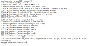
The chip is connected to the J-Link clone and debugged via the latest pyOCD version.?There are no scripts for it in openocd.?There is a pack for Keil that includes debugging.?Debugging in both cases is done via SWD.?A hardware reset pin is used. For debugging in the environment, you need to configure the embedded GDB server with the following parameters:- 'target remote' args: localhost: 3333.
- GDB Server: pyocd.
- GDB Server args: gdbserver --target w7500 --connect halt.
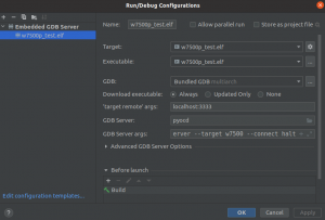 The process of flashing and starting debugging itself:
Flashing LED
As mentioned earlier, there is a ready-made module in lib_service that inverts the LED with a specified period in the vsrtos thread.?However, it requires a custom method to invert the LED.?So it's time to get acquainted with the hardware peripherals of the microcontroller.?At the same time, let's compare it with the STM32 peripherals.Structures of microcontroller periphery modules
All peripheral modules, except for the TCP / IP stack, have structures with peripheral registers in the demo code from the repository.?These structures differ from what can be drawn from the documentation, as there are many errors in the documentation.?The structures from the working demo project are the ultimate truth. There were no structures per TCP / IP module.?Only macros that wrap peripheral register addresses. For consistency, I rewrote this part in the manner of structures from more popular manufacturers such as STM.?The structures described in the periphery of the core containing?core.h?, a peripheral microcontroller?periph.h?library?lib_w7500x?.Clock Reset generator (CRG)
This is an analogue of RCC in STM32.?However, it has a number of the following differences:- All peripherals are enabled by default.
- PLL is enabled by default.?An internal 8 MHz RC circuit is used as the source, and the division and subsequent multiplication factors are 5 and 2, respectively.
- All clock lines after the PLL are connected to the peripheral blocks with a divider 1 (bypass).
- There are no mechanisms for analyzing the output to the required frequency or detecting a failure of an external HSE.?Instead, it is possible to output a signal from any clock bus to the GPIO pin.
- There is a separate frequency generator for MII_RXC and MII_TXC, powered by a separate external crystal resonator.?It can only be turned on or off.?The crystal should be at 25 MHz.?It is enabled by default.
- There are no recommendations for the sequence of settings in the documentation.?As well as the recovery mechanisms in case of setting erroneous coefficients.?The microcontroller will simply start to behave inappropriately if the HSE ratios are incorrect or if a poor-quality HSE is installed.
I / O ports (GPIO)
Everything is quite complicated here.?Instead of one GPIO + EXTI module, as is done with the STM32, here we have 3 + EXTI:- Alternate Function Controller (AFC) - this module provides functionality similar to the choice of the alternate function AFx in STM32F4 and similar.?Unlike STM32, all pins by default do not have an input function, but an alternative function corresponding to the most likely use case that the manufacturer assumes.?In this regard, in order to blink the LED, first you need to make sure that the required output is in GPIO mode, and not connected to any peripherals.?If connected, then you need to put it in the GPIO mode.
- External Interrupt (EXTI) - this module is about the same as in the EXTI module of the STM32F4, only simpler.?You can choose whether an interrupt is generated on the transition to the required level of the signal bus or not, and on the transition to which level (0 or 1) it will occur (we are talking about the signal on the internal bus between EXTI and GPIO, and not the signal at the pin input) ...
- Pad Controller (PADCON) - this module is designed to configure the parameters of the selected pin.?Here you can configure:
- Whether or not a lift to power or ground is needed.
- Output signal current (large / small).?Specific values ??for different configurations are listed in the reference manual on page 150, GPIO section.
- Whether the output is an open collector output or not (if not, then, as I understand it, it is analogous to push-pull).
- Whether the inline buffer is enabled on the input or not.
- Whether the Schmitt trigger is on or not.
- General-purpose I / Os (GPIO) - the module combines part of the RCC and part of the GPIO from stm32 and allows:
- Enable / disable outputs to pins (input mode is always enabled).
- Read data from inputs (after passing through buffers and Schmitt triggers, if enabled).
- Set data to pin outputs (will be displayed only if the pin output is enabled).
- Read / clear the status of the presence of interrupts on the pins.
- Select the interrupt operation mode: by level or falling / rising.
- Set the polarity (in case of triggering by coincidence of the level) or the boundary (in the case of triggering by the edge or falling edge) of the interrupt occurrence.
- Work with the module through the space of masks.
SYSTIC
For vsrtos to work, as with any preemptive RTOS, you need a timer.?This microcontroller has a standard SYSTIC, which is clocked from 6 MHz with an input frequency of 48 MHz fed to the core.?However, there is a nuance.?The documentation is missing the CLKSOURCE bit from the CSR.?I have never been able to figure out where the frequency is coming from at 0 in this bit.?But at 1, everything agrees with theoretical calculations.Working with TCP / IP stack
So we got to the main module, for which we started everything.?Theoretically, in order to start sending messages via UDP, you just need to configure the microcontroller pins, configure the PHY, wait for the cable to be connected, open the RX socket and send your data to the TX socket, ignoring the data in the RX socket (they are started in pairs).?However, a number of nuances arose here:- Since there are two crystals inside our microcircuit, some of the microcontroller's pins are not brought out and are connected directly to the PHY.?However, what exactly these conclusions are - we are not told.?But the study of the source code of the library, which wrote magic constants at non-existent addresses + a little deduction led to thoughts in which registers of which periphery the recording is going.
- There is an unconnected pin in the connection between the two crystals (MAC on one and PHY on the other), which causes ping to jump from 1ms to 700ms at times in transactions.?That for sending UDP packets directly by cable to the network card of the computer is significant.?Fortunately, errata has a special section on this.?They ask to assign constants to permanent addresses, which are not there .. Again, after reading the code in point 1, it became clear that a pull to the ground is hung on certain conclusions, and on others to the power supply.?And one output is generally set to a logical unit.?Hodgepodge that can be seen in init_miim_pins file functions?eth.c?library?lib_w7500x?.
- The PHY is not initialized through the MDIO interface.?He is simply not here.?Or there is, but we and those who wrote the demo code and documentation were not told about it.?Everything happens by means of manual pin control.?As it is customary to say among developers "bogus."?Alternately me pin assignment.?You can look at the slightly modified code for the jerk for MDIO in the functions mdio_idle, mdio_out, mdio_turnaround, mdio_in.?These methods are used by the mdio_get_data method to get the contents of the PHY registers.?The phy_init method initializes the pins and tries to get the integrated PHY ID using the get_phy_id method.?In my case, it was 5.
- As I said earlier, the second block of RAM is for the TCP / IP stack.?Namely:
- The 32 kilobytes are halved.?16 kilobytes for sending and 16 kilobytes for receiving.?These values ??are fixed and cannot be changed.
- Inside each block of 16 kilobytes, you can split the memory for the used sockets.?Depending on the task.?By default, 32 kilobytes are divided by the maximum number of supported sockets - 8 pieces.?That is, 2 kilobytes per socket for sending and 2 kilobytes for the same socket for receiving.
- The size of the buffer for transmitting and receiving for one socket can be set differently.?However, the sizes are multiples of two: 0, 1, 2, 4, 8, 16 kilobytes.?That is, in theory, you can create one socket, which will have 16 kilobytes for receiving and 16 for sending.?I left these parameters by default.
- Those areas of memory that are intended for each socket for receiving and transmitting represent a circular buffer inside themselves.?I will analyze it using the example of the transfer.?Suppose we have just started the work of the system.?We want to transfer 4 bytes.?For this we need:
- Read the current position in the circular buffer from the special pointer register.
- Take the address of the beginning of the buffer and add an offset to it inside the circular buffer.
- Copy the data to be sent to the buffer at the received address in step 2. If the buffer ended in the process of placing data for sending, then continue writing from the beginning.
- Put the previous value plus the length of the data that we have prepared for sending into the pointer register from point 1.
- The entire TCP / IP stack presents a state machine with many states and flags to the developer.?That is, in order to start communication for the first time, you first need to clarify that the state machine has been reset - the socket is closed.?Next, you need to configure the parameters and wait until the state machine goes into the state we need - connected.?The same applies to dispatch.?We make sure that the state machine is in the waiting state for the next transaction, set up the packet to send, put the state machine into the send state, and wait for either the transition to a timed out state or the end of the transfer.?The socket_udp_close, socket_udp_open and socket_udp_send methods of the?eth.c?library?file are responsible for opening a socket and then sending to it (with possible closing at the user's request)lib_w7500x?.
- You can copy data to a circular buffer using DMA.?But I did manual copying for the test, since this is only the first experience and there has not been any real application yet.
- The TCP / IP stack has an interrupt.?It can be configured both to trigger on general events of the entire module, and on specific events on each of the channels.?However, when transmitting small packets, its need is practically zero.?So the interrupt is not applied in the example.
PC connection
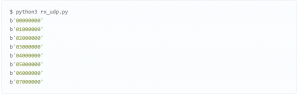
After collecting and stitching the project into the microcontroller, after rebooting, it will start sending data to a UDP socket to a static address and port.?It is important that the network on the computer is on the same subnet and statically configured.?Example for Ubuntu: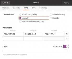 The project has a python script?rx_udp.py?that opens a receiver socket and displays incoming messages in binary form: