
[AIoT] Early Fire Detection using AI
Pico project that provides a quick alarm response to the people in the particular zone when a fire source or flame is detected.
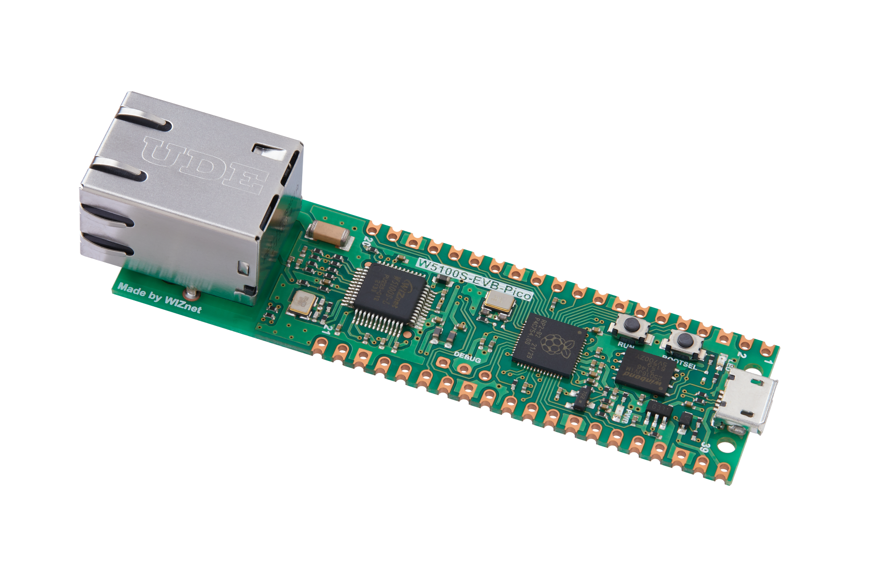
WIZnet - W5100S-EVB-Pico
x 1

adafruit - RGB Backlight LCD - 16x2
x 1
PIEZO BUZZER - MCKPT-G1210-3916.
x 1

Arduino - Arduino IDE
x 1
Introduction
One of the most common man made disaster is by fire. The project focuses on implementation in petrol pumps, and other fire zone and fire restricted areas. Today, we'll look at an unusual Pico project that provides a quick alarm response to the people in the particular zone when a fire source or flame is detected. The Advantage on real time applications is, it provides quick response before a smoke spread due to fire Whenever a fire/flame is detected it sends quick response to the peoples in the zone.
Components
Hardware
- Jumper wires
- Wiznet Pico board
- LED Bulb
- 330k Resistor
- 16*2 LCD Display
- Buzzer
- I2C Module
Software
- Yolov5 Object detection
- Arduino IDE
- Google Colaboratory
- PyCharm - Python IDE
Circuit diagram
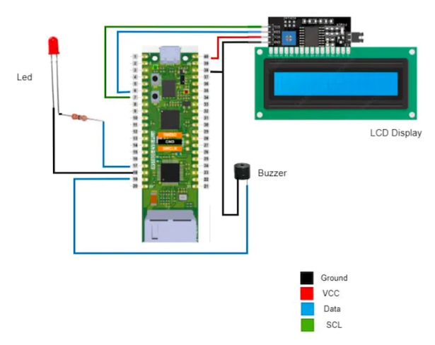
LED: Consist of 2 pins, positive pin which is connected to 330K resistor and GP13. and negative pin is connected to GND (ground).BUZZER: Consist of 2 pins in which positive pin is connected to GP14. Negative pin is connected to GND. 16*2 LCD Display with I2C Module: Consist of 4 pins. VCC, GND, SDA, SCL. VCC connected to 5V. SDA pin connected to GP4. SCL pin connected to GP5. GND can be connected to any GND of pico board.
AI diagram
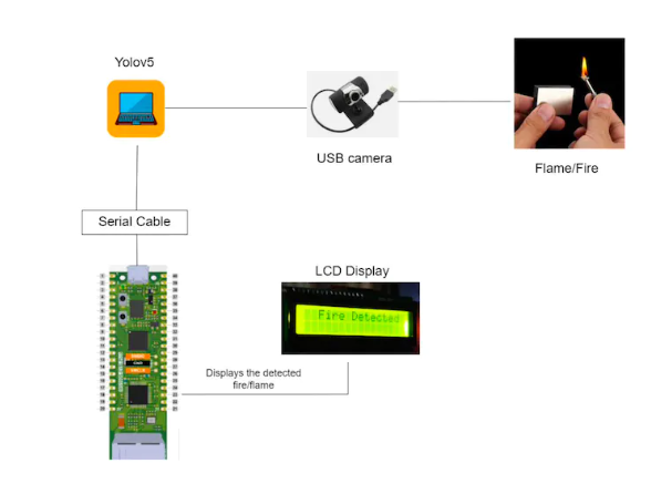
In this project, we have used the YOLOV5 object detection model on a custom trained datasets which could detect when a flame or fire source is found. Training is done by various fire sources such as lamps, lighters and matchsticks. The annotation is done with the collected real time flames and fire sources. Then feed it to the training algorithm. Ensure that the present working directory is the YOLOV5 directory and all dependencies are installed. The coco128.yaml file has to be updated with the datasets directory and also the classes used. Train using the command:
!python train.py --img 416 --batch 16 --epochs 100 --data coco128.yaml --weights yolov5s.pt --cache
A pertained weight has been assigned to the training [yolov5s.pt] and is running at 100 epochs. Once the training is done check in the “runs” folder to check the accuracy of predictions in the.jpg files. The real time detection can be used with the command:
python test.py --weights best.pt --img 416 --conf 0.28 --source 1
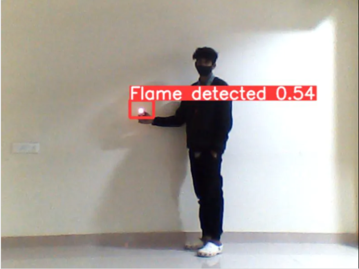
While running this command the present working directory should be the root of the yolov5 folder. The weight file ending in “.pt” file has to be given in the - -weight argument. The source can be set to 1 or 0 depending on the webcam used as internal or external. On running this command a frame opens up with bounding box detection. Through serial communication it sends the data and displays the status in LCD display, These status messages include “Fire detected”, when a flame or fire source is found using camera, in case no fire/flame are detected “No fire detected” command. On receiving the status via serial communication to raspberry pico, we check for keywords matching. A global variable is assigned for each status and this status will be displayed in the LCD display as well as the Serial Monitor.
Code Explanation:
Liquidcrystal_I2C library has to be added to the arduino sketch. Line [2 - 3] contains the libraries required for LCD display which is wire.h and Liquidcrystal_I2C.h. Line [7 - 10] Initializing variables for led, buzzer and a global variable data. Line [12 - 20] void setup contains pinMode of led and buzzer. Setting led and buzzer voltage level to low. Line [22] void loop starts. Line [25 - 28] while loop to read the data through serial connection. Line [31 - 44 ] if condition with data = h, where h is a keyword passed through serial communication. If the data read is “h” then the buzzer and led gets activated to indicate the fire detected. In LCD display “Fire detected ” message been printed. Line [46 - 59] else condition when there is “No fire” detected. when no fire is detected led and buzzer voltage level will be low.
References:
- https://towardsdatascience.com/early-fire-detection-system-using-deep-learning-and-opencv-6cb60260d54a
- https://create.arduino.cc/projecthub/shubhamsuresh/image-processing-based-fire-detection-extinguisher-system-57ddc3
- https://www.c-sharpcorner.com/article/how-to-create-a-fire-detection-alarming-system-using-arduino-uno-r3/
- https://www.researchgate.net/publication/356171734_Design_of_a_Home_Fire_Detection_System_Using_Arduino_and_SMS_Gateway
- https://create.arduino.cc/projecthub/shubhamsuresh/image-processing-based-fire-detection-extinguisher-system-57ddc3
-
Early Fire Detection
