
[AIoT] Laser turret using human hand tracking AI
A laser turret system that can detect and track the human hand using AI and computer vision.
Adafruit - SG90 Micro-servo motor
x 1
Proto Supplies - Laser Emitter Module
x 1
Adafruit - Solderless Breadboard Half Size
x 1
Adafruit - Jumper wires (generic)
x 1
OpenCV - OpenCV
x 1

.Mediapipe - Mediapipe
x 1
Project Description
In this project, we'll create a laser turret system that can detect and track the palm process the coordinates and then send the coordinates to the pico board which will use these coordinates to the servo motors and focus the laser on the detected object. All the detection, processing, and coordinate mapping is done by OpenCV and Python
How to Use servo motors, laser with Raspberry PICO
The servo motors are connected to the Pico board which will provide the X, Y coordinates to the laser and guide it to the detected object. There are two servos used in this project one is for the vertical motion and one is for the horizontal motion[X-Y Axis]. The pico board will receive the XY coordinates; these coordinates are sent to the servo motors which will move the laser pointer accordingly. The laser is powered by the pico board and is attached to the Y axis servo motor.
Things used in this project
1. Hardware
- Wiznet Pico board
- Jumper wires
- 2x SG90 Servo Motors
- Red laser pointer
- Bread Board
- Web Cam
2. Software
- Arduino IDE
- Python
- Libraries Included Arduino : Servo
- Libraries Included Python : cv2, mediapipe, numpy, serial
Story
The project is inspired by laser turret systems placed in battle ships which uses radar and video capturing to detect incoming fighter jets and missiles, track them and shoot them down with high accuracy. The Israel Iron Dome system is one of the most advanced versions of these systems to exist. This project uses a similar tracking system using AI. The coordinates after tracking are calculated and sent to the PICO board in an encoded format. The pico board will compute the X-Y coordinates and send these to the X-Y servo motors respectively. A laser is attached to the Y servo motor as for the pointing. As the detected object moves the laser pointers will also move according to it in realtime. Serial communication is established between the detection and pico board at 115200 baud rate. The servo will be active only when serial data is received. This eliminates the need of writing the same coordinates to the servo over and over again improving latency of the servo movement.
Circuit diagram Explanation
VCC, GND[Pin 36, Pin 38] are connected to the X and Y Servo motors and the laser pointer. PWM of the X-Axis servo is connected to GPIO 0 [Pin 2]. PWM of the X-Axis servo is connected to GPIO 1 [Pin 2]. Serial USB is attached to the Pico to read the incoming coordinate string. The VCC pin supplies 3.5V output which will power the laser pointer.
How to integrate AI ?
In this project OpenCV and Mediapipe are used for palm detection. The X and Y coordinates of the palm of a certain point. These X and Y coordinates are then translated to servo angles using the translate function. Two prevent two writes for X and Y coordinates the data is combined to a single string and is passed to the Serial COM port. This is done for each frames The String is encoded in ‘utf-8’ format.
Python AI Code Explanation
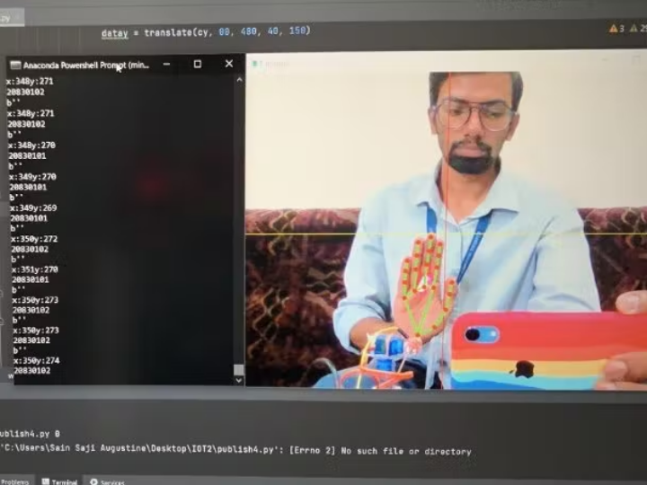
First we import all the libraries required for capturing, processing and writing to Serial Port, line number 2-6. We initialize the serial communication in line number 9. Serial port is given as COM3, Baudrate is set to 115200 and a timeout of 0.1 second is given for each writes. OpenCV video capturing is enabled as set to 0 for internal webcam. We use a hands class from mediapipe for palm detection. Line 19-82 is an infinite loop which captures frames until the program is closed. Line no 28, 29 sets up horizontal and vertical lines for the capture screen. The midpoint has to be aligned with the laser pointer. Line no 20-25 converts the captured frame to an RGB colorspace and is then given for processing. From line number 31 to 43, if palm is detected the X, Y coordinates of the palm is calculated from by multiplying with screen width and height A translate function is used to convert the XY coordinates to Servo Angles. This done by mapping the X Coordinate which range from 640 to 0 the Servo angle range 20 to 160.Similiarly the Y coordinate is converted from range 0 to 480 to the Servo angle range 40 to 150. The translate function is then called, the inpval variable is the coordinate. The translate function has the following arguments inpval which is the input coordinate, in_from and in_to which is the range of the incoming coordinates. out_from and out_to are the angles to which the range has to be converted. Once the conversion is done these values will be stored to variables datax and datay for X and Y coordinates respectively. Line no 70-74 is to encode the X and Y coordinates to a single string. This is done by the converter function which takes two arguments x, y which are the translated angles. In line no 70-74 the translated and encoded data is sent to the Serial COM port. In Line number 84 to 87 the processed and landmarked capture is shown.It is inverted in the X axis to show the real image.
Arduino Code Explanation
The code starts from line number 2, which includes the Servo library which activates the servo motor. Two servos are initialized in line number 5, 6.Two variables are initialized in line number 9, 10 in which serialdata is to capture incoming serial string and a variable midpoint which is to set the laser pointer to the middle of the screen. In the void setup() function the Servo motors are attached and Serial is enabled at baudrate = 115200 and a time out of 1 millisecond is given for the incoming serial data. The servos are initialized to an angle of 90, to set the laser to middle in the initial position. Line number 23 to 26 is set as empty as we are not continuously checking for the incoming serial data. A function is written to check for any serial communication in line no 32-46. It reads the incoming serial data in String format; it is then converted into integer format for calculating the X and Y coordinates. The string is in encoded format which has both the X and Y coordinates. Cordinates will be in the form 2xxx0yyy eg:20390107.where xxx is the X coordinate and yyy will be Y coordinate eg:X=39 and Y=107. This has to be extracted and it is done by line number 40-42 which sets two variables X and Y which are then written to the X and Y servo motors in line number 44 and 45.
You can find the source code on the GitHub.
-
Laser Turret using human hand tracking AI

-
Circuit Diagram

-
AI Integration