Pico Remote control Lamp (coded with chatGPT prompt)
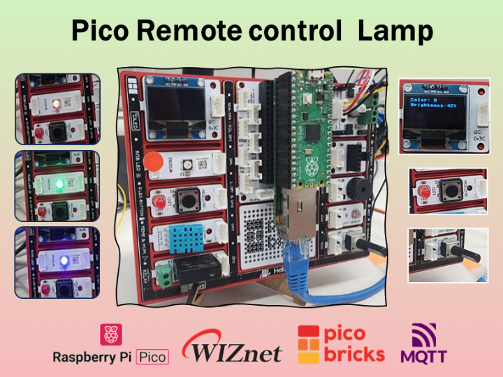
This project showcases control and lamp devices for adjusting lamp color and brightness via MQTT, with info display on OLED.
Software Apps and online services
Introduce
Have you ever found your home uncomfortably dark after stepping out? Worried that you might have left the lights on when you went out? This project offers a seamless solution. Using a control device and a lamp, you can remotely adjust the lamp's color and brightness, effortlessly illuminating your space.
This project was made using the code interpreter feature of chatGPT4. Please refer to the history below
I will explain the process of the project in a very easy and simple way. So, let's get started!!
Function definition
I will create two devices. One will serve as a control device for managing the lamp, and the other will function as the actual lamp that can be turned on. Both devices will be remotely controlled through MQTT. Here are the specifics.
- Control Device
- The controller device will use MQTT to transmit JSON data to the RGB lamp. This data will include information to adjust the RGB color and brightness of the lamp.
- The controller device will have a push button that controls the RGB color of the lamp. Pressed for less than 0.5 seconds, it will select the RGB color.
- The controller device will adjust the brightness of the lamp using a variable resistor. Values will be mapped to brightness levels 1 ~100.
- Show the RGB color and brightness information of the lamp on the OLED display.
- RGB Lamp Device
- The RGB lamp device will receive JSON data via MQTT from the controller device. This data will include information to adjust the RGB color and brightness of the lamp.
- The RGB lamp device will adjust its RGB values and brightness based on the received JSON data.
- Show the RGB color and brightness information of the lamp on the OLED display
Hardware Preparation
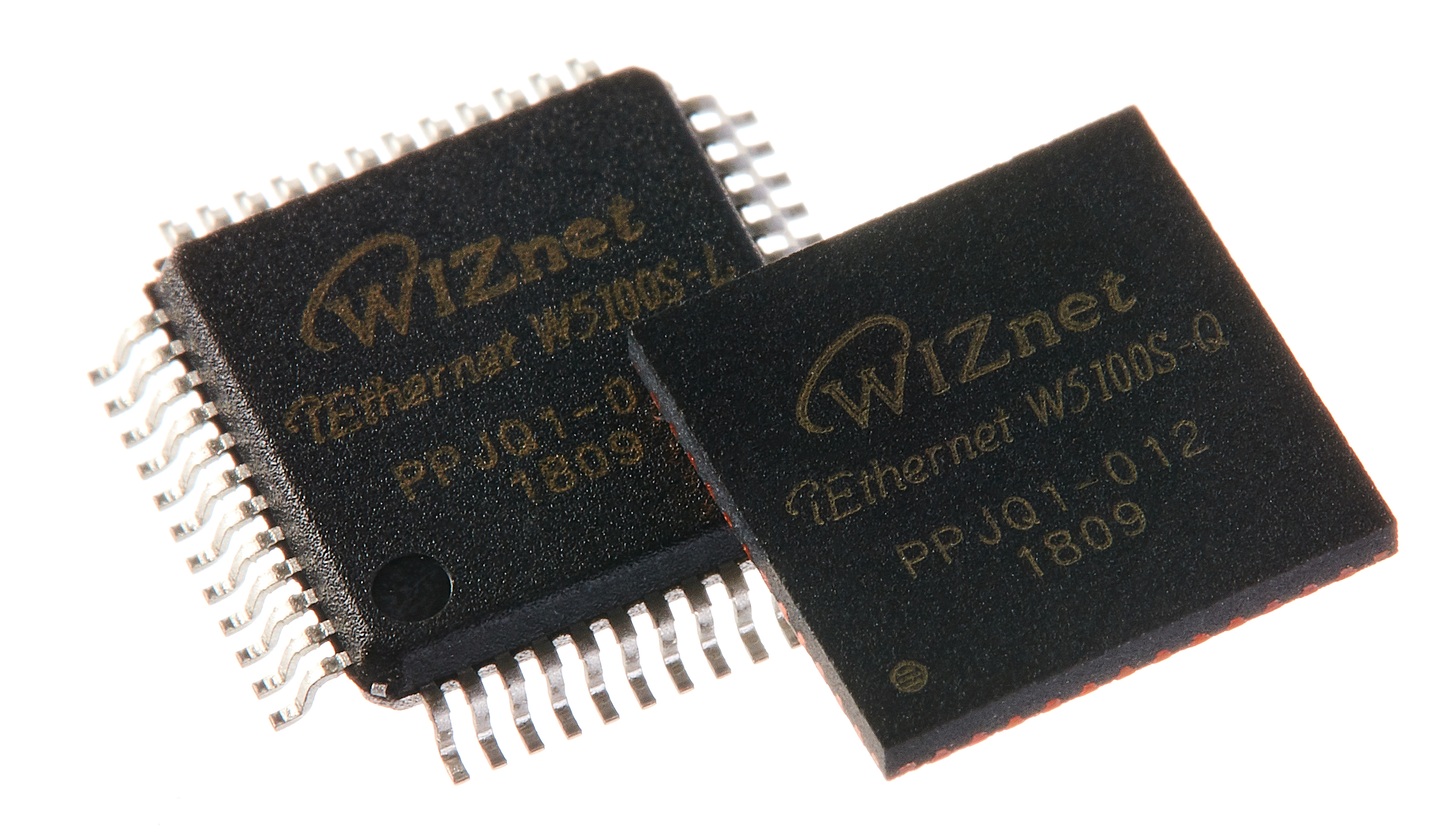
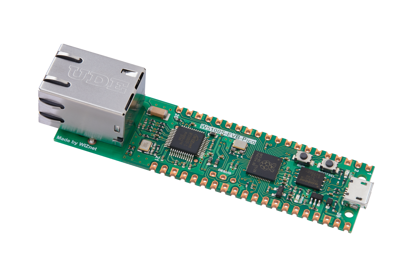
-W5100S-EVB-Pico
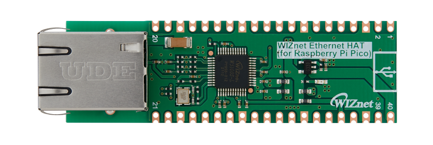
I am using a combination of PICO+WIZnet Ethernet HAT, and Pico Bricks that I have been consistently using recently.

- Pico: https://www.raspberrypi.com/products/raspberry-pi-pico/
- WIZnet Ethernet HAT: https://eshop.wiznet.io/shop/module/wiznet-ethernet-hat/
- W5100S-EVB-Pico: https://eshop.wiznet.io/shop/module/w5100s-evb-pico/
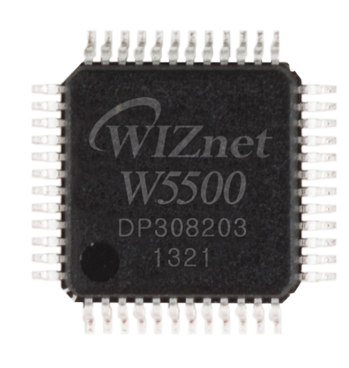
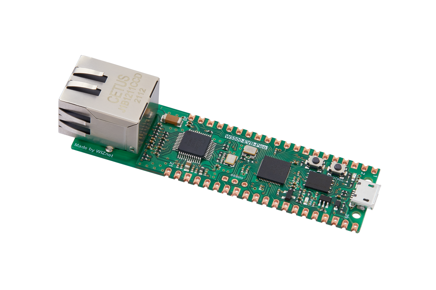
- W5500-EVB-Pico: https://eshop.wiznet.io/shop/module/w5500-evb-pico
I have used two units of both PICO and WIZnet Ethernet HAT, as well as two units of Pico Bricks.
Furthermore, using Pico+WIZnet Ethernet HAT instead of W5100S-EVB-Pico or W5500-EVB-Pico is also a viable option.
- Pico Bricks
The modules to be used are RGB LED, Button, Potentiomater and two of OLED.
Modules data sheet https://docs.picobricks.com/en/latest/datasheet.html
It is also possible to detaching and use the modules of a single Pico Bricks instead of purchasing two separate Pico Bricks.
SW Configuration
1. Firmware Configuration
I have updated the FW in Git. Please select according to the Ethernet chip version.
https://github.com/wiznetmaker/RP2040-PicoBricks-HAT-Micropython/tree/main/pico_uf2
If you need the latest version, you can check it on the micro python homepage.
Downloading the firmware follows the same steps as setting up other MicroPython device.. If you find it difficult, you can refer to this YouTube video for assistance:
WIZnet Pico Board How to Program WIZnet Pico board using MicroPython https://www.youtube.com/watch?v=8FcFhZRNNxE
2. Network
To use WIZnet W5x00 series, import network module for using WIZNET5K module.
Enter network information and SPI information to connect to W5100S. The IP of the lamp device and the control device are set differently.
DEVICE_IP = "192.168.11.101"
GATEWAY = "192.168.11.1"
NETMASK = "255.255.255.0"
DNS = "8.8.8.8"

SPI_BAUDRATE = 2000000
SPI_MOSI = 19
SPI_MISO = 16
SPI_SCK = 18
SPI_CS = 17
SPI_RST = 20
and the network init function is below.
def wiznet_init():
    spi = machine.SPI(0, baudrate=SPI_BAUDRATE, mosi=machine.Pin(SPI_MOSI), miso=machine.Pin(SPI_MISO), sck=machine.Pin(SPI_SCK))
    nic = network.WIZNET5K(spi, machine.Pin(SPI_CS), machine.Pin(SPI_RST))
    nic.active(True)
    nic.ifconfig((DEVICE_IP, NETMASK, GATEWAY, DNS))
- MQTT
And set up MQTT. The MQTT functions are in lib/WIZnet_MQTT.py
Sets the information for using MQTT and the callback function to be used when receiving subscrpt.
The user name of the lamp device and the control device are set differently.
Subscript is used only in the lamp device and is registered as a callback function during MQTT initialization. (It is set to None in the control device.) Additionally, in the main loop While True:, using the mqtt.check_msg() function checks for subscript messages and invokes the callback.
USERNAME = "umqtt_client"
BROKER_IP = "192.168.11.100"

SUB_TOPIC = "ctrl_state"
PUB_TOPIC = "chack_state"
KEEP_ALIVE = 60
 ...

def main():
	...
	mqtt = WIZnet_MQTT.WIZnetMQTT(USERNAME, BROKER_IP, PUB_TOPIC, SUB_TOPIC, KEEP_ALIVE, mqtt_sub_callback)
 	mqtt.init_mqtt()

    ...
	while True:
    	#check subscript messages. only Lamp Device.
		mqtt.check_msg()
    ...
In the mqtt_sub_callback function, extract the color and brightness of the lamp from the received subscription message. And control the lamp accordingly.
def mqtt_sub_callback(topic, msg):
    color_dict = {
    'R': (255, 0, 0),
    'G': (0, 255, 0),
    'B': (0, 0, 255)
    }
    print((topic, msg))
    try:
        # Check if msg is of type bytes and decode it
        if isinstance(msg, bytes):
            msg = msg.decode('utf-8')

        data = json.loads(msg)
        color = data.get("color", None)
        brightness = data.get("brightness", None)

        if color not in ["R", "G", "B"]:
            print("Invalid color value!")
            return
        if not 0 <= brightness <= 100:
            print("Invalid brightness value!")
            return

        neo.set_neopixel(color_dict[color], brightness/100)
        update_oled_display(color, brightness)

        print(f"Received color: {color}, brightness: {brightness}")
    except Exception as e:
        print(f"Error decoding JSON! Details: {e}")
The 'publish' function takes a string data as a parameter. When the button and potentiometer values change, create a JSON message with the color and brightness values and publish it
    # Generate JSON message and publish
    message = generate_json_message(rgb, brightness)
    mqtt.publish(message)
3. Modules
The control logic for the Pico Bricks module is written based on the official provided library picobricks.py and is included in picobricks_utils.py
https://github.com/wiznetmaker/RP2040-PicoBricks-HAT-Micropython/tree/main/lib/picobricks_utils.py
If you are using Pico Bricks, you can use it without any additional GPIO settings. However, if you are using other modules, please input the GPIO values in the initialization functions of each module accordingly.
Example
from picobricks_utils import picobricks_neopixel as _PB_neopixel
PB_neopixel= _PB_neopixel(neopixel_pin= 6)
- Control: Potentiometer
It checks every 0.1 seconds and operates when the current value differs from the previous one.
lib/picobricks_utils.py/ class picobricks_potentiometer
from picobricks_utils import picobricks_potentiometer as _PB_POT
PB_BTN= _PB_POT()
If you want to change the checking speed, please adjust the value of 'get_pot_timer'.
   global last_brightness
   prev_pot_value = None
   current_pot_value= 0
   last_pot_check = time.time()
   get_pot_timer = 0.1

   while True:
		...
        # Check Potentiometer value
        if (time.time() - last_pot_check) > get_pot_timer:
            current_pot_value = pot_value_scaled()
            if current_pot_value != prev_pot_value:
                print(f"Brightness Value changed to: {current_pot_value}")
                update_display_and_publish_message(last_rgb, current_pot_value)
                prev_pot_value = current_pot_value
                last_brightness = current_pot_value

            last_pot_check = time.time()
- Control: Button
Press the button once to select colors in the order of R, G, and B
lib/picobricks_utils.py/ class picobricks_button
from picobricks_utils import picobricks_button as _PB_BTN
PB_BTN= _PB_BTN()
If you want to change the current button detect time, please input the new detect_time_ms
PB_BTN= _PB_BTN(detect_time_ms= 500)And upon receiving the input signal for the button, you can set the callback function to be executed
PB_BTN.set_button_callback(push_callback=push_callback_setRGB)Let's create a function that changes the state from R to G to B ... based on the push action.
lib/picobricks_utils.py/ class RGBController
import picobricks_utils
RGB_Ctrl = picobricks_utils.RGBController()
The button is used in a push format. Add logic to set the button state in the actual operation's 'while' loop. Detect button inputs and execute the callback accordingly.
while True:
	# Check for button pushes
    button_push_main()
Create the 'push_callback_setRGB' function.
def push_callback_setRGB():
    global last_rgb, last_brightness
    RGB_Ctrl.cycle_rgb_state()
    cur_rgb = RGB_Ctrl.get_rgb_state()
    last_rgb = cur_rgb
    update_display_and_publish_message(cur_rgb, last_brightness)
-Lamp: RGB LED
Adjust the color and brightness of the lamp based on the JSON data received from mqtt_sub_callback.
lib/picobricks_utils.py/ class picobricks_neopixel lib/picobricks_utils.py/ class RGBController
from picobricks_utils import picobricks_neopixel as _PB_neopixel
PB_neopixel= _PB_neopixel()
Change the brightness value to 1/100. (The lamp brightness value ranges from 0 to 1 and increases by 0.01)
neo.set_neopixel(color_dict[color], brightness/100)- Lamp/ Control: OLED
Display the color and brightness of the lamp on the OLED.
lib/picobricks_utils.py/ class picobricks_oled
from picobricks_utils import picobricks_oled as _PB_oled
PB_oled= _PB_oled()
For the control device, the values change when the button and potentiometer values change.
def update_display_and_publish_message(rgb=None, brightness=None):
    # Update OLED display
    PB_OLED.print_line_oled(f"Color: {rgb}", f"Brightness:{brightness}%")
For the lamp device, the values change when receiving MQTT messages.
def update_oled_display(rgb=None, brightness=None):
    PB_OLED.print_line_oled(f"Color: {rgb}", f"Brightness:{brightness}%")
If you want to display the message in a different format, utilize the OLED class.
class picobricks_oled:
	def print_to_oled(self, string, start_x=5, start_y=5):
	def print_line_oled(self, line1='', line2='', line3='', line4='', line5=''):
	def print_string_oled(self, string, start_x=5, start_y=5, max_len=15, line_spacing=10):
My project is now complete!uite a straightforward project, isn't it? This serves as a basic project that lays a foundation for more ideas to come. For instance:
Smart Home Mood Lighting System: Create a smart lighting system for home automation that automatically adjusts the lighting based on time of day or user preferences. This system can help set the ambiance and create a comfortable environment in your living space.
Interactive Art Installation: Build an interactive art installation using the project as a foundation. Use buttons and sensitivity controls to manipulate the lamp's color and brightness, creating dynamic and interactive media art.
Personalized Wake-Up Light: Utilize the lighting system to craft a personalized wake-up light. Gradually brightening the light in the morning can provide a gentle and customized way to wake up.
Remote Workspace Illumination: Implement a solution to optimize workspace lighting remotely. Adjust the lamp's color and brightness from a distance, enhancing work productivity and convenience.
Learning Tool for Electronics and IoT: Use this project to create a learning tool for electronics and the Internet of Things (IoT). By incorporating components such as buttons, potentiometers, and an OLED display, learners can gain hands-on experience with communication concepts and deepen their understanding of electronics and IoT.
Surprisingly, I didn't write any code myself. (Actually, I'm a C developer, and I'm a beginner in Python, LOL.) I tried out the beta service of the code interpreter in GPT-4 this time. The results were incredibly satisfying. I utilized over 95% of what chatGPT provided as-is for this project.
Throughout the project, I experimented with various prompts and documented the process. I'll be sharing how to effectively use GPT for coding with you.
Expect to hear from me within a week!

