AutomaticGreenhouse
This project is to design and build a solar powered outdoor greenhouse that can monitor and control the temperature & humidity of the air as
0
Components
Hardware components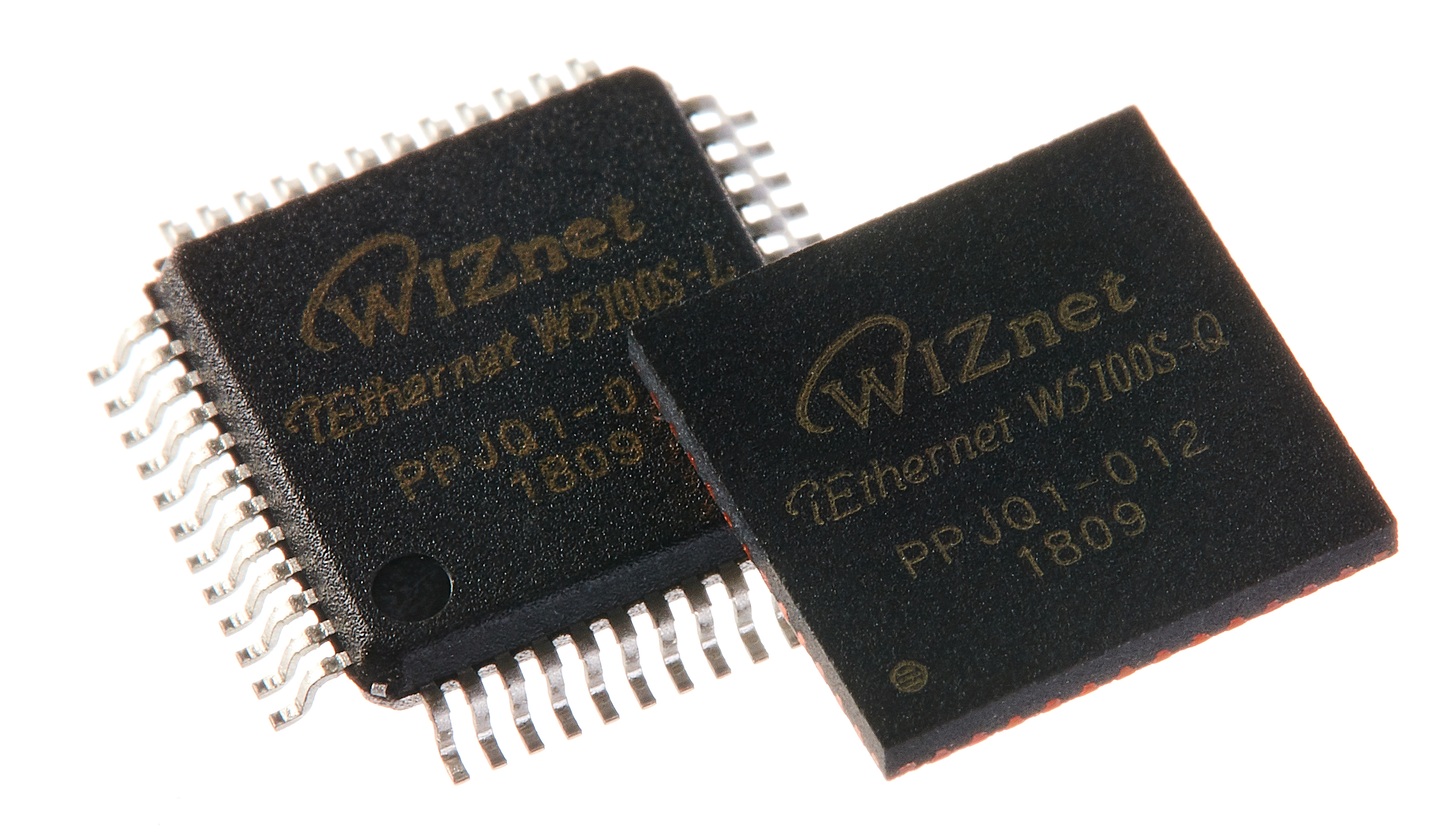
WIZnet - W5100S
x 1


Seeed Studio - Grove - I2C High Accuracy Temp&Humi Sensor (SHT35)
x 1

Seeed Studio - Grove - I2C UV Sensor (VEML6070)
x 1

M5Stack - I2C Hub 1 to 6 Expansion TCA9548A Module
x 1
Project description
utomaticGreenhouse
Introduction
This project is to design and build a solar powered outdoor greenhouse that can monitor and control the temperature & humidity of the air as well as automatically water the plants using collected rainwater.
The design of this project is intended to be highly modular, with the ability to chain multiple target nodes (units) together to allow for data to be combined and analysed by a single controller node. The power supply from the solar power system will also be chained to allow for a more simple power distribution setup.
Contents
| Topic | Description |
|---|---|
| Design | An overview of the design of the project |
| Monitoring | An overview of the design of the project |
| Parts Lists | Up to date parts lists for the project |
| PCBs | Information regarding the design and manufacture of the custom printed circuit boards |
| Networking | Information regarding the communication between the target nodes and the controller node. |
Design
Each target node in the system will be based upon a Raspberry Pi Pico and all hardware interfacing will be done using a custom PCB. The controller node will be a Raspberry Pi 4 managed using Balena. Communication between the target nodes and the controller node is documented in networking.
Each node will feature space for 6 planters, and will have a modular irrigation system to allow for planters to be easily added and removed.
Each node will feature the following sensors:
- Temperature
- Air Humidity
- Soil moisture sensors (1 per planter)
- Light Level (front and back of unit)
- Water level to monitor irrigation system
- Camera (optional: adds ability to implement timelapses and machine learning)
Each node will feature the following control systems:
- Light (LED strips)
- Temperature/Humidity (DC Fan)
- Soil moisture (Water Solenoid/Pump)
An overview of the system layout can be seen below. 
Monitoring
Currently monitoring is done using InfluxDB and Grafana running on a Raspberry Pi 4B. This is also running an MQTT broker and is using Node-Red to recieve and sanitize the telemetry before inserting it into InfluxDB.
The current Grafana dashboard can be seen below.

Parts Lists
Note the following parts lists are not complete and may change.
The following parts are required to build one node PCB.
| Part | Qty | Description |
|---|---|---|
| Pi Pico | 1 | The microcontroller used to control the node. |
| TCA9548A I2C Multiplexer | 1 | I2C multiplexer to allow connection of up to 8 soil humidity sensors with the same I2C address |
| N-Channel Mosfet | 5 | Control outputs |
The following sensors are required to build one node.
| Sensor | Qty | Description |
|---|---|---|
| Temperature/Humidity | 1 | Monitor air temperature and humidity in the greenhouse. |
| Soil Humidity | 6 | Monitor soil humidity of each planter. |
| Light Sensor | 2 | Monitor wavelengths of light to optimise growth. |
| Water Level Switch | 1 | Monitor the stored water level to trigger an alert if it gets too low. |
PCBs
The PCBs are designed in EASYEDA and can be ordered from JLC PCB.
The parts for the PCBs can be found in the Parts Lists.
Networking
The communication between the target nodes and the controller node will be handled using MQTT over Ethernet.
The controller node will act as an MQTT broker and also as a client. Each of the target nodes will be provisioned with unique ID's by the controller node using the following procedure:
- Target node generates random ID, uses this as Client ID
- Target node sends "Connection Request" mqtt message to the controller node on topic greenhouse/{Client ID/connection.
- Target node begins listening on topic greenhouse/{Client ID}/response
- The Controller node verifies the target node can connect, and returns a new production ID on the topic greenhouse/{Client ID}/response
- The Target node stores this production ID in the EEPROM and uses this as it's client ID
This procedure ensures that the Controller node can always identify the Target node even after restarts. It also means that if a Target node PCB is replaced, the new Target node PCB can be programmed with the correct client ID so that the data remains consistent for that unit.

