Regarding ESP32 Ethernet Design
Regarding ESP32 Ethernet Design
0
Project description
1. Summary of URL Content (`[https://devicein.tistory.com/177](https://devicein.tistory.com/177)`)
This document (Part 2 of the ESP32 Ethernet design series) covers the design considerations and pin connection requirements for connecting the ESP32 series MCU to Ethernet at the hardware level.
* When using the ESP32's internal MAC (Direct connection to a PHY chip)
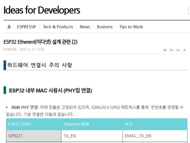
* RMII Interface: Basic pins such as TX_EN, TX0, TX1, RX0, RX1, and CRS_DV are fixed; pin assignments cannot be changed.
* REF_CLK Pin: Can be selected from GPIO0, GPIO16, or GPIO17; however, since GPIO0 is also a bootstrap pin for firmware flashing, the design must incorporate a sufficient delay to prevent accidental entry into flashing mode.
* SMI (MDC/MDIO): Pin assignments can be freely changed.
* Reset Pin: Must be connected to one of the ESP32 GPIO pins for hardware reset during initialization.
* When using an external SPI Ethernet controller (SPI connection)
* An SPI connection is used when there is no internal MAC or when flexible pin assignment is required.
* SPI pins are not fixed and can be configured via firmware.
* Major supported SPI Ethernet controller chips: W5500, DM9051, KSZ8851SNL, ENC28J60, CH390, etc.
2. Summary of the W5500's Role
The W5500 is an SPI-to-Ethernet controller chip with an embedded hardware TCP/IP stack, developed by WIZnet. * Standalone Ethernet Communication: Enables easy addition of wired Ethernet (LAN) capabilities using only an SPI interface (CLK, MOSI, MISO, CS), even if the MCU lacks an integrated Ethernet MAC or PHY.
* Reduced MCU Load: Handles the hardware TCP/IP protocol stack (TCP, UDP, IPv4, ICMP, ARP, IGMP, PPPoE, etc.) directly within the chip, significantly reducing CPU resource and memory consumption for the main MCU (e.g., ESP32).
* Design Convenience: Operates via SPI pin connections, minimizing GPIO pin usage and simplifying circuit design.
3. System Architecture
* Data Path
* Internal MAC Mode (RMII): Data travels through the ESP32's built-in Ethernet MAC. The MAC interfaces with an external PHY chip via fixed RMII pins (TX_EN, TX0, TX1, RX0, RX1, CRS_DV). The management data is handled by SMI (MDC/MDIO), which can be remapped.
* External Controller Mode (SPI): For ESP32 models without an internal MAC (like the S2, S3, or C series), data is transmitted from the MCU via SPI (CLK, MOSI, MISO, CS) to an external Ethernet controller like the W5500 or DM9051. SPI pins are fully assignable via firmware.
* Power Path
* A critical constraint mentioned for hardware integration is the REF_CLK routing (e.g., GPIO0). Proper signal timing and delays during power-up are strictly required on GPIO0 to prevent the ESP32 from inadvertently entering boot-strap (FW flashing) mode during reset sequences.
4. Related Projects
4-1. ESP32-S3 Ethernet Design (W5500)
Link: ESP32-S3 Ethernet Design (W5500)
Key Content: This project explains the characteristics of the ESP32-S3—which lacks a built-in Ethernet MAC—and covers design guidelines within the ESP-IDF framework for interfacing with SPI-based external Ethernet controllers (such as the WIZnet W5500, DM9051, or KSZ8851SNL).
Relevance to the Tistory Post: This is the most direct hardware comparison and design project that expands upon the original post's content regarding "Ethernet support by ESP32 model and SPI Ethernet controller (W5500) specifications" from a maker's perspective.
4-2. Implementing Ethernet-based JPEG Streaming with ESP32-CAM + W5500
Link: ESP32-CAM + W5500 Ethernet Streaming
Key Content: This guide demonstrates how to implement wired JPEG streaming without pin conflicts by connecting the W5500 via the HSPI interface (using GPIO pin remapping), thereby resolving the issue where the default VSPI pins on the ESP32-CAM module are already occupied by the camera.
Relevance to the Tistory Post: This is a prime example of applying the original post's key principle—that "unlike RMII pins, SPI Ethernet pins (MISO/MOSI/CLK/CS) are not fixed and can be designed by freely adjusting GPIO numbers in the firmware"—to a real-world hardware constraint (camera pin occupancy).
4-3. ESP32 OTA Firmware Update via W5500 Ethernet Module
Link: ESP32 OTA via W5500 Ethernet
Key Features: This project implements a reliable wired network-based remote firmware update (OTA) system using a dual-bank flash architecture, connecting the ESP32 and W5500 via SPI.
Relevance to the Tistory Post: This is a fully realized project that adapts Espressif’s official Ethernet initialization component (`espressif/ethernet_init`) and the W5500 SPI backhaul infrastructure—introduced in the original post—into a wired firmware update offloading system essential for industrial environments.
[Q&A]
Q: When implementing Ethernet communication on a microcontroller (MCU) like the ESP32, what are the main reasons for using an external SPI Ethernet controller (such as the W5500) instead of directly connecting an external PHY chip to the built-in MAC?
A:
The primary reasons are pin utilization flexibility and the conservation of MCU resources.
Flexibility in Pin Assignment: When using the ESP32's built-in MAC to connect a PHY chip (via RMII), key communication pins (e.g., GPIO21, 19, 22) are fixed and cannot be changed, and hardware constraints—such as specific requirements for handling GPIO0—arise. In contrast, the W5500 uses an SPI interface, allowing pin assignments to be freely configured in firmware, which offers much greater flexibility in circuit design.
Reduced CPU Load via Hardware TCP/IP Stack: The W5500 features a hardware-implemented TCP/IP protocol stack. Consequently, the MCU does not need to process network protocols in software, leading to a dramatic reduction in CPU and RAM usage. Compatibility with MCUs lacking an integrated MAC: Wired Ethernet functionality can be easily added—using only an SPI connection—even to the latest target chipsets that do not have an internal Ethernet MAC, such as the ESP32-S2/S3 and ESP32-C3/C6.
=========================

blog : https://devicein.tistory.com
1. URL 내용 요약 (`[https://devicein.tistory.com/177](https://devicein.tistory.com/177)`)
해당 문서(ESP32 Ethernet 설계 관련 2편)는 ESP32 시리즈 MCU를 하드웨어적으로 이더넷(Ethernet)에 연결할 때 필요한 설계 및 핀 연결 주의사항을 다루고 있습니다.
* ESP32 내부 MAC 사용 시 (PHY 칩 직접 연결)
* RMII 인터페이스: TX_EN, TX0, TX1, RX0, RX1, CRS_DV 등 기본 핀이 고정되어 있어 핀 번호 변경이 불가능합니다.
* REF_CLK 핀: GPIO0, GPIO16, GPIO17 중 선택할 수 있으나, GPIO0은 펌웨어 라이팅 보드 부트스트랩(boot strap) 핀이므로 라이팅 모드로 잘못 진입하지 않도록 충분한 지연(Delay) 설계가 필요합니다.
* SMI (MDC/MDIO): 핀 번호를 자유롭게 변경 가능합니다.
* Reset 핀: 초기화 시 하드웨어 리셋을 위해 ESP32 GPIO 중 하나에 연결해야 합니다.
* 외부 SPI Ethernet 컨트롤러 사용 시 (SPI 연결)
* MAC이 없거나 핀 할당을 유연하게 하려는 경우 SPI 방식으로 연결합니다.
* SPI 핀은 고정되어 있지 않으며 펌웨어에서 조정이 가능합니다.
* 지원되는 주요 SPI 이더넷 컨트롤러 칩: W5500, DM9051, KSZ8851SNL, ENC28J60, CH390 등.
2. W5500의 역할 요약
W5500은 위즈넷(WIZnet)에서 개발한 하드웨어 TCP/IP 내장 SPI 이더넷 컨트롤러(SPI-to-Ethernet Controller) 칩입니다.
* 독립형 이더넷 통신 제공: MCU에 이더넷 MAC이나 PHY가 없더라도 SPI 인터페이스(CLK, MOSI, MISO, CS)만을 이용해 유선 이더넷(LAN) 통신 기능을 손쉽게 추가할 수 있게 합니다.
* MCU 부하 경감: 하드웨어 TCP/IP 프로토콜 스택(TCP, UDP, IPv4, ICMP, ARP, IGMP, PPPoE 등)을 칩 내부에서 직접 처리하므로, 메인 MCU(ESP32 등)의 CPU 리소스와 메모리 소모를 대폭 줄여줍니다.
* 설계 편의성: SPI 핀 연결만으로 작동하므로 GPIO 핀 사용을 줄이고 회로 설계를 간소화할 수 있습니다.
3. 시스템 아키텍처
* 데이터 경로
* 내부 MAC 모드 (RMII): 데이터는 ESP32의 내장 이더넷 MAC을 통해 전송됩니다. MAC은 고정된 RMII 핀(TX_EN, TX0, TX1, RX0, RX1, CRS_DV)을 통해 외부 PHY 칩과 인터페이스합니다. 관리 데이터는 SMI(MDC/MDIO)를 통해 처리되며, 해당 핀은 재매핑이 가능합니다.
* 외부 컨트롤러 모드 (SPI): 내부 MAC이 없는 ESP32 모델(S2, S3 또는 C 시리즈 등)의 경우, 데이터는 MCU에서 SPI(CLK, MOSI, MISO, CS)를 통해 W5500이나 DM9051과 같은 외부 이더넷 컨트롤러로 전송됩니다. SPI 핀은 펌웨어를 통해 자유롭게 할당할 수 있습니다.
* 전원 경로
* 하드웨어 통합 시 중요한 제약 사항은 REF_CLK 라우팅(예: GPIO0)입니다. 리셋 시퀀스 중 ESP32가 의도치 않게 부트스트랩(펌웨어 플래싱) 모드로 진입하는 것을 방지하기 위해, GPIO0의 전원 인가 시 신호 타이밍과 지연 시간을 엄격하게 준수해야 합니다.
4. 유사 프로젝트
4-1. ESP32 S3 이더넷 설계 (W5500)
링크: ESP32 S3 이더넷 설계 (W5500)
주요 내용: 내장 이더넷 MAC이 포함되지 않은 ESP32-S3의 특성을 설명하고, SPI 기반 외부 이더넷 컨트롤러(WIZnet W5500, DM9051, KSZ8851SNL 등)를 연동하기 위한 ESP-IDF 프레임워크 차원의 설계 지침을 다룹니다.
Tistory 글과의 연관성: 원본 글의 "ESP32 제품별 이더넷 지원 여부 및 SPI 이더넷 컨트롤러(W5500) 지원 규격" 내용을 메이커 관점에서 그대로 확장하여 설명한 가장 직접적인 하드웨어 비교·설계 프로젝트입니다.
4-2. ESP32-CAM + W5500으로 이더넷 기반 JPEG 스트리밍 구현하기
링크: ESP32-CAM + W5500 이더넷 스트리밍
주요 내용: ESP32-CAM 모듈에서 기본 VSPI 핀이 이미 카메라에 할당되어 점유된 상황을 해결하기 위해, W5500을 HSPI 인터페이스(GPIO 핀 재배치)로 우회 연결하여 핀 충돌 없이 유선 JPEG 스트리밍을 구현한 가이드입니다.
Tistory 글과의 연관성: 원본 글의 핵심 지침인 "RMII 핀과 달리 SPI 이더넷 핀(MISO/MOSI/CLK/CS)은 고정이 아니며, GPIO 번호를 펌웨어에서 자유롭게 조정하여 설계할 수 있다"는 원칙을 실제 하드웨어 제약 조건(카메라 핀 점유)에서 적용한 대표 사례입니다.
4-3. ESP32 OTA Firmware Update via W5500 Ethernet Module
링크: ESP32 OTA via W5500 Ethernet
주요 내용: ESP32와 W5500을 SPI로 연결하여 듀얼 뱅크 플래시(Dual Bank Flash) 구조 기반의 안정적인 유선 네트워크 원격 펌웨어 업데이트(OTA) 시스템을 구현한 프로젝트입니다.
Tistory 글과의 연관성: 원본 글에서 소개한 Espressif의 공식 이더넷 초기화 컴포넌트(espressif/ethernet_init) 및 W5500 SPI 백홀 인프라를 활용하여 산업용 현장에서 필수적인 유선 펌웨어 업데이트 오프로딩 시스템으로 응용한 완성형 프로젝트입니다.
[Q&A]
Q: ESP32와 같은 마이크로컨트롤러(MCU)에서 이더넷 통신을 구현할 때, 내장 MAC과 PHY 칩을 직접 연결하는 방식 대신 W5500 같은 외부 SPI 이더넷 컨트롤러를 사용하는 주요 이유는 무엇인가요?
A:
가장 큰 이유는 핀 활용의 유연성과 MCU의 리소스 절감 때문입니다.
핀 배치 및 선택의 자율성: ESP32의 내장 MAC을 이용해 PHY 칩을 연결(RMII 방식)할 때는 주요 통신 핀(GPIO21, 19, 22 등)이 고정되어 있어 변경할 수 없으며, GPIO0 처리 등 하드웨어 제약이 발생합니다. 반면 W5500은 SPI 인터페이스를 사용하므로 핀 번호를 펌웨어에서 자유롭게 지정할 수 있어 회로 설계가 훨씬 유연해집니다.
하드웨어 TCP/IP 스택을 통한 CPU 부하 경감: W5500은 칩 내부에 TCP/IP 프로토콜 스택이 하드웨어로 구현되어 있습니다. 따라서 MCU가 소프트웨어로 네트워크 프로토콜을 처리할 필요가 없어 CPU 및 RAM 메모리 소모를 획기적으로 줄일 수 있습니다.
내장 MAC이 없는 MCU 호환성: ESP32-S2/S3, ESP32-C3/C6 등 내부 이더넷 MAC이 없는 최신 타깃 칩셋에서도 SPI 핀 연결만으로 간단하게 유선 이더넷 기능을 추가할 수 있습니다.
