
Smart UPS Monitor & Home Lab Power Distribution Board
Smart UPS-s Monitor and 12V Power Distribution Board designed to maximize device up-time during power outages.
In this project I will present a home lab power distribution solution aimed provide reliable power to devices and maximize uptime during power outages.
The solution consists of two hardware devices:
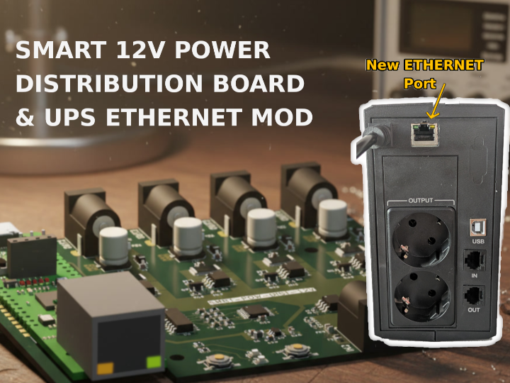
- Smart 12V Power Distribution board with W55RP20 - power and controls 12V to devices such as routers, modems and single board computers
- UPS Ethernet / LAN Mod with WIZ-IP20 - an Uninterruptible Power Supply (UPS) enhanced with LAN connectivity
These two devices are combined with custom software / automation in order to safely handle power failures and maximize device uptime.
Part 1 | 12V Smart Power Distribution board with W55RP20-EVB-Pico
In home networking many devices, such as routers, switches, modems, security cameras or even single board computers (SBC) use 12V power adapters as supply. To provide reliability in case of power failure, these devices are often connected to an UPS.
Having too many devices connected to an UPS can reduce the time frame the UPS is able to provide backup power in cause of an outage. Because of this it can beneficial to have monitoring on the UPS, and reduce its load only to what is essential when an outage happens.
To be able to control devices I designed a Smart Power Distribution Board (12V) that is used to distribute 12V power to multiple devices. The power to each device can be controller individually, while sharing the same supply for efficiency.
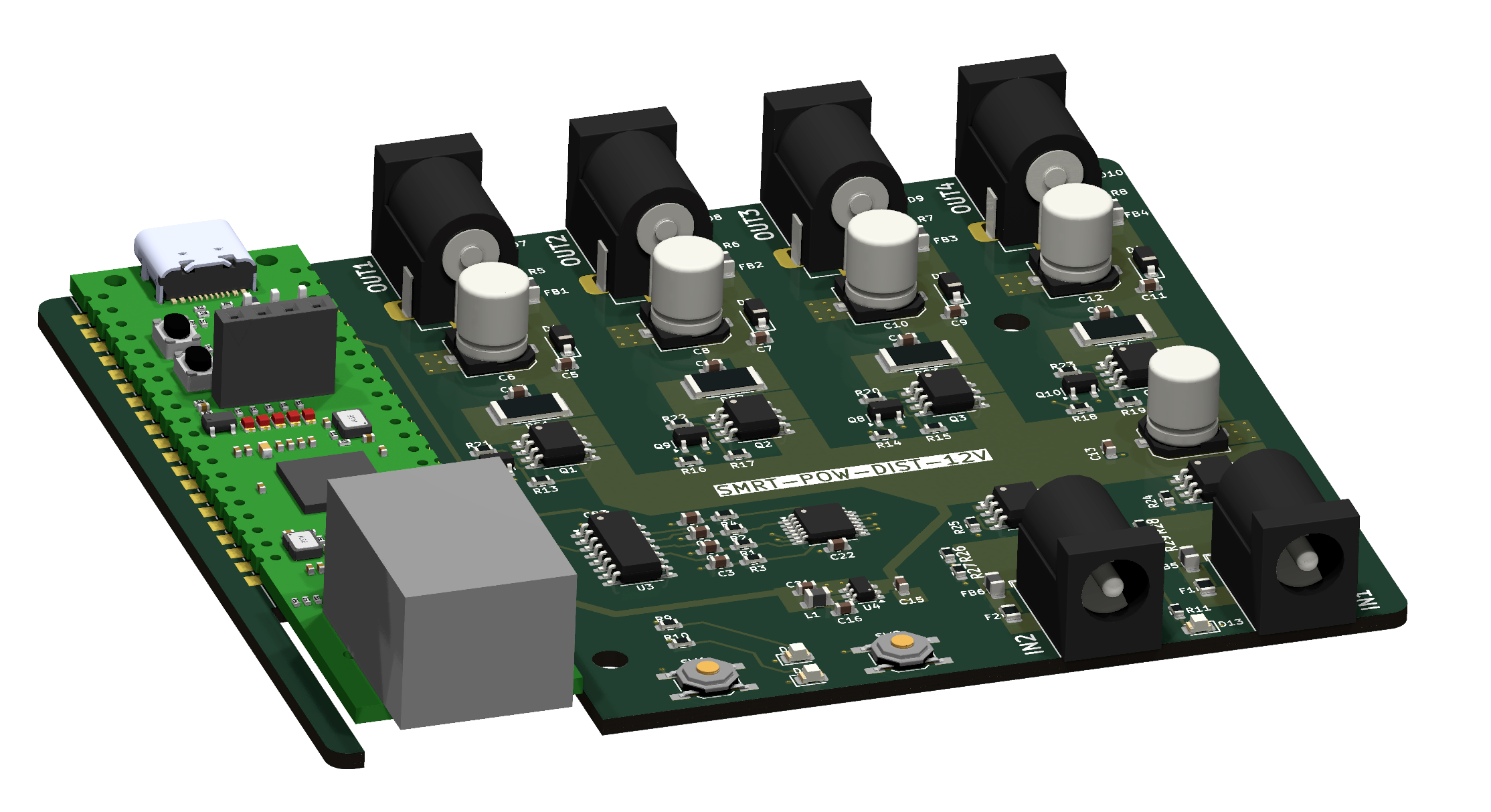
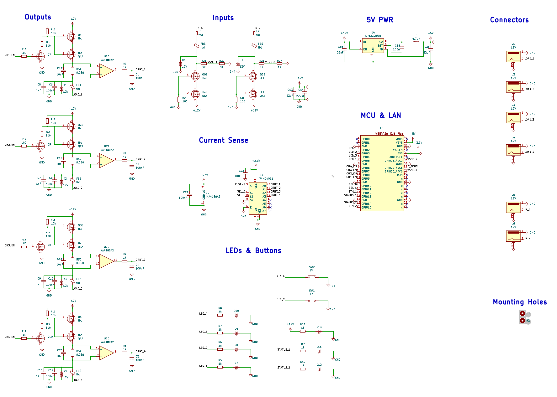
The board is designed around the W55RP20-EVB-Pico eval kit providing Ethernet connectivity. It has 4 x individually controller outputs, and 2 x inputs for additional redundancy. Input and outputs have various protections, and the continuous current monitoring even allows detecting faulty devices.
The board was designed in KiCad, and uses a simple 2-layer board with single side component placement for efficient assembly.
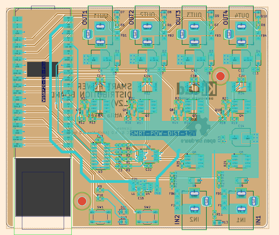
Note: the hardware is currently in manufacturing at JLCPCB.
The firmware uses the arduino-pico core and has various features such as:
- MQTT (secure) command interface
- Local command interface with basic functionality (Switch / LED)
- Individual channel configuration
- Sequenced startup
- Soft circuit breaker
- and others
The device is intended to be used in automation setups as follows:
- A script / system continuously monitors the UPS status to detect power outage.
- In case of a power outage the UPS battery level is monitored.
- When the UPS battery level falls bellow a threshold, the script commands the power distribution board to shut down non essential devices.
- When the power is restored, the script commands power up of shut down devices.
Part 2 | UPS Ethernet Mod with WIZ-IP20
Uninterruptible Power Supplies (UPS) often come with an USB port the can be used for monitoring. This allows things like gracefully shutting down a PC in case of power outage before the is battery fully drained.
However, when the UPS is used to power networking, home lab and IoT devices, is often not practical to use the USB port as this usually needs a PC or SBC only to handle the USB connection. For this reason an UPS with built in LAN connectivity would be much more easy to use.
⚠️ Warning: Please DO NOT try modify 230V equipment at your own if you're not qualified! ⚠️
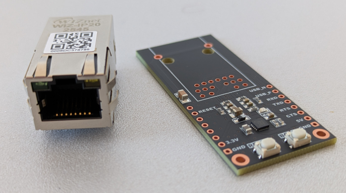
In this part I will show how to use a WIZ-IP20 module to add Ethernet connectivity to an UPS. The WIZ-IP20 module will be used to convert the existing USB/Serial interface of the UPS to LAN.
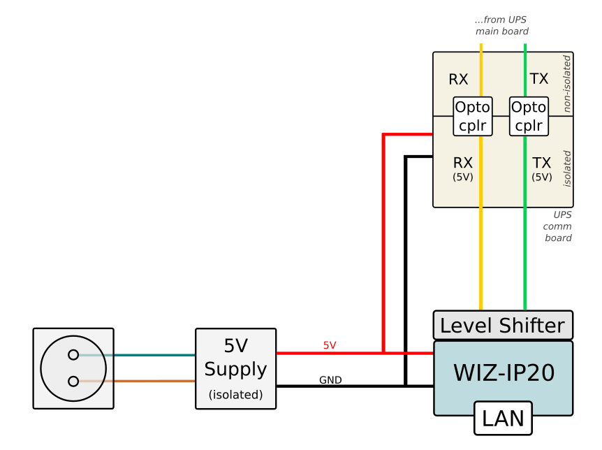
My particular UPS, similarly to many generic UPS-s, exposes an USB / Serial port implementing the Megatec / Blazer Protocol. The UART RX/TX lines (isolated) were exposed in a separate comm board, and I used this as the inputs for the WIZ-IP20. Two slight complications were that UPS uses 5V logic level, so I needed hack in a level shifter circuit to convert the signals to the 3V3 level used by the WIZ module. Also, there was no 5V power present on the isolated side of the UPS comm board (normally it uses 5V from USB), so I added 5V AC-DC power supply (isolated) to power the new circuit.
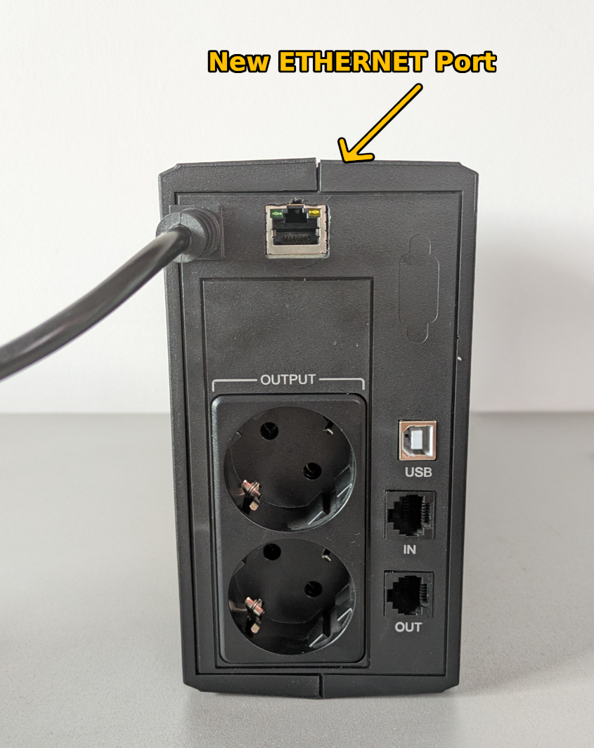
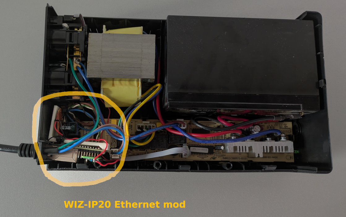
To integrate the new LAN port I cut a hole in the UPS's case, and fixed the WIZ-IP20 module to the case using a 3D printed bracket and some zip tie (note: this 1st prototype is a bit flimsy and I may redesign it a some point).
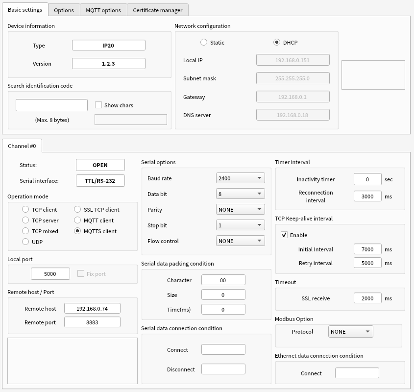
One wired up we can use the WIZnet-S2E-Tool-GUI tool to configure the WIZ-IP20 module. I set the following:
- Network configuration - DHCP
- Operation mode - MQTTS
- Serial options: 2400 baud
In the MQTT Options tab we need to set username, password and a publish and subscribe topics:
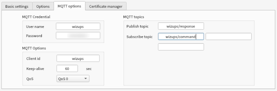
With this the WIZ-IP20 was configured to connect to my secure MQTT server, and use two dedicated topics for the UART send / receive channels. This setup allows clients such as scripts and automations to easily query the UPS's current state and take actions if needed.
-
12V Power Distribution Hardware and Firmware
Hardware design (KiCAD) and Firmware (Arduino)

-
UPS LAN Mod Schematics

-
12V Power Distribution Schematics