SCADA Cyber Range
Down the Rabbit Hole: Fostering Active Learning through Guided Exploration of a SCADA Cyber Range
8
Project description
Abstract
Prior experience from the authors has shown that a heavily theoretical approach for cybersecurity training has multiple shortcomings, mostly due to the demanding and diversified nature of the prerequisites, often involving concepts about operating system design, networking and computer architecture, among others. In such circumstances, the quest for trainee engagement often turns into a delicate balancing act between managing their expectations and providing an adequate progression path. In this perspective, hands-on exercises and contact with high-fidelity environments play a vital part in fostering interest and promoting a rewarding learning experience. Making this possible requires having the ability to design and deploy different use case training scenarios in a flexible way, tailored to the specific needs of classroom-based, blended or e-learning teaching models. This paper presents a flexible framework for the creation of laboratory and cyber range environments for training purposes, detailing the development, implementation and exploration of a cyber range scenario, within the scope of a course on cyber-physical systems security. Moreover, the course structure, curricular aspects and teaching methods are also detailed, as well as the feedback obtained from the students.
1. Introduction
Despite the evolving nature of the cybersecurity field, as well as the progress achieved over the past years, the ever-changing landscape of threats, vulnerabilities and attack vectors means that there is still much work to be done, with new issues being disclosed on a regular basis. As the demand for specialized cybersecurity professionals grows [1], we have reached the point where the industry needs exceed the output of the educational establishment—including academies and other specialized training organizations, corporate training, universities and, in some cases, the military.
This situation is aggravated by the fact that, for most computer science undergraduate students, cybersecurity is just another specialization field that faces stiff competition from alternatives such as data science or software engineering. Moreover, because cybersecurity is an orthogonal topic to many roles and specialization profiles within the CS and IT domains, there is also the need to promote awareness for a broader public. This calls for a differentiated educational offer, both in terms of quality and didactic approach, focused on recruiting, engaging and preparing students to become capable professionals with a mindset geared towards excellence.
Unarguably, the investment in updating and promoting good pedagogical practices can be one of the potentially differentiating aspects of a good instructor. On the organizational level, such efforts must be matched by appropriate investment in resources and infrastructures, way beyond the implementation of supervisory methodologies or survey-based quality management policies that often do little more than providing evidence to reinforce a diagnosis that has long been known: traditional teaching methods are often inadequate when it comes to motivating students.
Is this perspective, differentiation emerges as a key ingredient of a successful training strategy: with a wealth of online contents available, it is up to instructors to add value beyond the often passive nature of such resources, promoting proximity and accessibility, regardless of the learning model that is adopted. Over the past years of pedagogical practice, the authors were able to recognize a set of clues that characterize the most common dysfunctions and imbalances in trainee groups—impatience and lack of prerequisite knowledge are among the most frequent. This calls for the adoption of selective scaffolding procedures in order to make content accessible, preparing and encouraging trainees to become involved in hands on activities as quickly as possible.
When it comes to cybersecurity training, hands-on exercises and contact with high-fidelity environments play a vital role in promoting active learning—such exercises may range from Capture-The-Flag (CTF) challenges, self-contained within Virtual Machines, to working with emulated or simulated environments, for pentesting, vulnerability assessment or to provide practical experience on dealing with various simulated attacks and threats. The ability to develop the latter on a safe environment is crucial for the implementation of a comprehensive organizational cybersecurity framework, helping teams to develop much needed preparedness and incident response skills. Nevertheless, designing and deploying use case scenarios tailored for training purposes, such as the ones used on cyber ranges, requires both access to an adequate support infrastructure as well as a high degree of flexibility in terms of resource management—this is no easy task, regardless of opting for in-premises or cloud-based hosting model.
This paper addresses the aforementioned aspects by presenting a comprehensive, end-to-end, take on the subject:
First, it presents a flexible framework for the creation of laboratory and testing environments for training purposes, detailing the design and development of a cyber range environment based on a Supervisory Control and Data Acquisition System (SCADA) process, conceived for a cybersecurity course taught at the University of Coimbra. This scenario was designed from the ground up to enable students to interact with a highly realistic environment, composed of real and emulated/simulated components.
Second, this paper documents how the cyber range is leveraged to foster engagement in course-level exploratory activities, providing trainees with first-hand experience acquired by dealing with a high-fidelity cyber-physical system. In this perspective, a training plain is presented, designed to familiarize students with the terminology and technologies used in Industrial Control Systems (ICS), as well as with the several domain-specific risks, vulnerabilities and attack profiles.
Regarding the latter point, note that the specific methodological and teaching strategies adopted in the aforementioned plan are also presented, showcasing how the ICS cyber range is leveraged to enable a differentiated pedagogical approach. The proposed learning path is aligned with a bottom-up strategy that starts with an introduction about the specific characteristics of ICS architectures, equipment and programming, next moving into the study and execution of scouting and reconnaissance procedures on the cyber range, which will later pave the way for an attack planning and deployment step. Note that the scouting, planning and attack execution steps are deployed in order to guide trainees through a simple pentesting process that will be concluded with an analysis of the existing vulnerabilities and the discussion of possible countermeasures and mitigation techniques.
The remaining of this paper is organized as follows. The next section presents a synthetic state-of-the-art overview on didactic approaches and testbed designs conceived for research and training purposes. Next, the design and implementation details for the cyber range used for training purposes will be introduced, together with a presentation of a flexible laboratory framework that supports it. After introducing the cyber range, the paper will focus on the the presentation of an introductory course on ICS security which was designed to take advantage of it, detailing the course structure as well as the didactic approach that is used. Section 5 presents and summarizes the results and feedback obtained from student performance assessment enquiries over the past three course editions, with Section 6 concluding the paper.
2. A Quick Review of Testbeds and Cyber Ranges for Training and Research
This section provides a literature review on several related efforts on the topic of cybersecurity testbeds, cyber ranges and didactics, which are deemed to be of interest in the context of this paper. Nevertheless, it should be stressed that this is not, by any means, an exhaustive analysis.
Accordingly with NIST’s definition [2], “Cyber ranges are interactive, simulated representations of an organization’s local network, system, tools, and applications that are connected to a simulated Internet level environment. They provide a safe, legal environment to gain hands-on cyber skills and a secure environment for product development and security posture testing. (…) Students can use cyber ranges to apply knowledge in a simulated network environment, develop cyber skills, work as teams to solve cyber problems, and prepare for cyber credentialing examinations. Educators can use cyber ranges as a classroom aide or instruct or assess students virtually.” This definition is mostly shared by other sources, as it is the case for the European Cyber Security Organization (ECSO) [3].
Several colleges and education/training institutions include specific cybersecurity courses in their curricula, covering topics like network security, cyber threat intelligence and risk assessment, among others. Very often, cyber ranges, cyber security training and simulation platforms are used to support learning activities, giving students the opportunity to participate in realistic scenarios [4], assuming specific roles based on the nature of the exercises (for example, in red/blue team drills). This is true, for example, of the cybersecurity curricula offered at De Montfort University (UK) [5] and Coimbra (PT) Universities [6]. Also within this scope, Trabelsi et al. [7] developed a technique for introducing essential concepts such as network keylogging and eavesdropping threats, after considering existing approaches to teaching cybersecurity-related topics. The authors suggested a group-based strategy in which students have access to workstations that have the CommView network analysis and packet sniffing programs installed. A similar proposal, geared towards security auditing practice activities is proposed in [8], which presents a methodology for teaching network traffic anomaly detection techniques utilizing an IP darkspace monitor, resorting to the MATLAB, tcpdump, corsaro, and RapidMiner tools. They also present a concept for a network security laboratory, designed for instructional purposes.
Within the realm of domain-specific testbeds, the work in [9] presents a flexible cybersecurity training laboratory that allows for scenario customization. This honeypot-based laboratory, which is used to assist undergraduate and postgraduate activities at Northumbria University (UK), was also created with hackathon events in mind. Lee et al. [10] provide another example of a laboratory designed for competitive purposes—the NetSecLab—which has also been used to teach systems and network security concepts, allowing students to obtain the fundamental skills needed to cope with cybersecurity concepts.
The creation of a SCADA testbed (water tank storage control system) for cybersecurity research is discussed in [11]. This testbed was created to allow for the execution of cyberattacks for the purposes of impact analysis and dataset development, with the latter being used to investigate machine learning (ML) algorithms for intrusion detection. Despite its research-oriented nature, the testbed design has pedagogical potential. Similarly, the work in [12] presents the Hybrid Environment for Development and Validation (HEDvA) testbed, which provides a blueprint for building a hybrid testbed environment employing a mix of physical equipment, simulation models, emulated components, and virtual machines—this method simplifies the process of setting up virtual labs by selecting and configuring components from inventory pools.
On a larger scale, two important examples stand out: JAMK’s Realistic Global Cyber Environment (RGCE) [13] and the ITrust’s Secure Water Treatment (SwAT) [14,15]. The RGCE was designed as a comprehensive hybrid testbed that allows to create custom scenarios encompassing interdependencies for different infrastructure and organizational levels, which can be used for training or research purposes. SwAT is a reference testbed that includes a communications network layer and a complete real SCADA setup that has been used to cybersecurity research and training purposes, also spawning a dataset which has been shared with the research community. Besides SwAT, the iTrust Centre of the Singapore University of Technology and Design has also developed other testbeds [15] for Energy Systems (dubbed EPIC, for Electric Power and Intelligent Control—which covers Generation, Transmission, Micro-Grid, Smart Home and Control domains), Water Distribution (WADI) and for IoT.
Even governmental and institutional agencies have been concerned about cyber ranges, with a particular focus on the ICS domain. For instance, as of 2017, ENISA’s “Prioritites for EU Research” [16] report stated that “The current challenge is to extend the capabilities of cyber-ranges to user domain specificities, such as SCADA, ICS, mobile devices, health related devices and IoT devices etc. (…)”, thus explicitly reinforcing not only the importance of the ICS domain, but also of building ICS cyber range platforms. In the wake of these efforts, projects and initiatives such as ERIGrid 2.0 (European Research Infrastructure supporting Smart Grid, and Smart Energy Systems Research, Technology Development, Validation and Roll Out), which congregate several associate Labs [17], are also putting a considerable effort on the development of real and virtual facilities for research and training, as well as into exploring the benefits of infrastructure federation (an example of this the VILLAS4ERIGrid federated lab effort [18]). While this specific initiative is mainly geared towards power system optimization and validation efforts, the main principles behind it are equally valid for the cybersecurity domain.
Overall, and considering the aforementioned examples, the HEDvA was perhaps the most important, motivating various architectural decisions that influenced the design of the CANVAS laboratory, which is presented in the next section, as well as the specific cyber range scenario that supports the training module hereby presented.
3. Development of the Cyber Range Environment
This section starts by presenting a flexible framework for the creation of laboratory and testing environments for training and research purposes, allowing students to interact with highly realistic environments composed of real and emulated/simulated components. This framework was used to build a SCADA ICS cyber range, whose design and development is thoroughly documented, from a process-centric perspective up to the specific details of its implementation.
3.1. The CANVAS Laboratory
The complete cyber range environment is supported on top of the CANVAS (Compositional Assembly of Validation Ambient Scenarios) laboratory environment (see Figure 1), which follows a three-tier design, encompassing asset, infrastructure and laboratory environment layers.
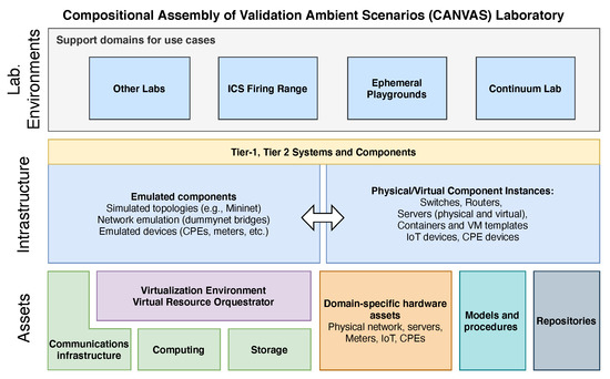
Figure 1. CANVAS laboratory environment.
An asset layer provides physical (real equipment) and virtualized computing resources, intellectual property (models and procedures contributed by end users) and data repositories. Assets may be flexibly allocated to build real and emulated scenarios for specific use cases. The infrastructure layer further develops the scenarios built from the assets, both real and emulated, available in the lab inventory. Finally, the topmost layer corresponds to the laboratory environments hosting the supporting domains for the use cases, integrated to provide the realistic conditions required for development, testing and validation of use cases or specific environments.
CANVAS constitutes a flexible framework enabling the development, refinement and implementation of a wide array of scenarios. The specific laboratory organization is arranged along a metastructure, with each functional block providing a set of coherent resources and services, which may be leveraged to build use case scenarios by means of composition. CANVAS was designed from scratch as a flexible environment composed of several assets such as equipment (process-related, as well as computing capabilities), processes and/or models, allowing to develop hybrid scenarios ranging from isolated cyber-physical testbeds to complete end-to-end environments, to test and validate concepts and solutions in a controlled, high-fidelity environment.
The benefits of this approach are manifold:
Safeguard infrastructure integrity, avoiding the deployment of components in production environments (and risking associated liabilities), providing a safe environment for teaching, pen testing and security analysis procedures (among which the latter two are known to be especially risky in production environments—NIST SP800-82 [19] provides such examples, also describing the potentially damaging outcomes). As such, these procedures could be safely developed and evaluated in a controlled environment, using real equipment, potentially providing invaluable data to the security community.
Avoid loss of time and effort in dealing with security clearances, authorization procedures and other unforeseen aspects (such as the lack of authorization from specific OEM providers for vulnerability assessment procedures).
Allow for the creation of custom environments with different specifications, replicating processes and procedures used in production environments using hybrid topologies, composed of real equipment and processes, together with emulated/simulated parts, along the lines of an evolved digital twin.
Develop effective testing methodologies for defense against attacks on specific equipment, networks and systems, to measure the cyber resilience of a given scenario with different types of attacks/severity.
Develop experiments to obtain a deeper understanding of different types of attacks, new techniques and defense technologies through the evaluation of different test scenarios and use/abuse cases.
Moreover, CANVAS was designed to be integrated with existing testbeds from other partners, by means of federation, enabling the development of more elaborate use cases. Such federated cyber range testbeds and/or pilot sites may be designed to support training, development and evaluation efforts, by providing an environment for deployment and testing. Moreover, federation may be used for scenario composition, eventually creating interdependencies which could cause cascading effects.
3.2. SCADA ICS Automation Process
The SCADA ICS testbed scenario used for the cyber range environment scenario is based on a solar-based heating system that uses thermal oil for heat transport and exchange between a set of panels and a network of heating coils. The thermal fluid is heated on heat pipes contained within the solar collector panels and, once it reaches an initial setpoint (40 degrees Celsius), an electric pump is started at a fixed speed, making the fluid circulate in a closed circuit that comprises an auxiliary tank and two heaters (cointaining the heat exchange coils). A second setpoint (80 degrees celsius) activates a second speed preset for the pump, which increases the speed of the thermal fluid flow. Figure 2 depicts the Human–Machine Interface (HMI) for this specific process.
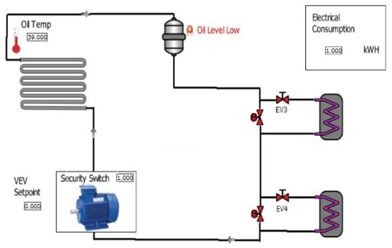
Figure 2. HMI for the SCADA process.
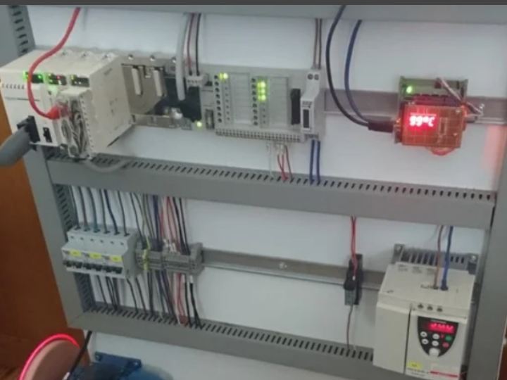
The SCADA system deployed for this cyber range monitors the operation of the whole process, obtaining information from the temperature sensors and electricity consumption probes, but also controlling the emulated valves and a real 3-phase motor for the pump. This cyber-physical process is emulated using a mix of real equipment and virtualized component instances, with the physical setup being shown in Figure 3.

Figure 3. Automation testbed.
Figure 4 depicts the logical testbed topology. The fluid pump is simulated by an electric 3-phase motor driven by a Variable Frequency Drive (VFD), allowing multiple speeds. A Modicon M340 Programmable Logic Controller (PLC) controls the VFD, via its discrete I/O channels. The motor speed is controlled by the PLC, based on a set of predefined liquid temperature setpoints.

Figure 4. Testbed topology.
Temperature measurements are provided by a Modbus Remote Terminal Unit (RTU) device providing a temperature gauge—this device provides the RTU functionality as well as the temperature probe emulation, whose value is controlled by a potentiometer. The Modbus RTU is based on an Arduino microcontroller connected to a wired ethernet network shield equipped with a Wiznet W5100 ASIC [20].
The PLC establishes an horizontal communication pattern with the RTU, providing insights of how this type of communications may play a crucial role on the ICS. The PLC also communicates with the Human–Machine Interface (HMI), which provides the supervisory interface for the system. Communications between the RTU, the PLC and the HMI are supported by means of the Modbus/TCP protocol [21].
3.3. Complete CANVAS Scenario
The complete hybrid environment for the cyber range, contains a mix of virtualized and physical equipment instances, integrated within a layered IEC 62443-compliant [22] structure (see Figure 5).

Figure 5. Cyber range environment (green VMs used for students; yellow VMs support services and testbed components for the specific scenario).
This scenario was entirely built by tapping into existing CANVAS assets and resources, including (but not limited to) physical equipment, communications infrastructure, computing resources, Virtual Machine (VM) templates and template service sets (as it is the case for the HMI + SCADA Honeypot VMs, depicted below). It is structured as follows.
Level 0 contains the sensors and actuators used by the the SCADA process that provides the main use case for the environment. Note that as the Arduino RTU also emulates a virtual temperature probe, its context crosses both the Level 0 and 1 domains;
Level 1 contains the process control equipment, both the PLC and Arduino-based RTUs used by the aforementioned cyber-physical process, but also a set of additions, namely a virtual PLC (based on the OpenPLC platform [23], and hosted on a VM) and a low-interaction SCADA honeypot configured to resemble a real PLC device;
Level 2 contains the operational SCADA nodes: two production HMI VMs, one for the cyber-physical process and one for the emulated process that runs on the virtual PLC (vPLC) instance; one SCADA station VM with an OPC UA (Unified Architecture) server and PLC programming and provisioning software; and a honeypot HMI VM which communicates with the SCADA honeypot, providing a complete setup designed to increase the engagement of a potential attacker;
Level 3 contains a remote access station VM, providing managed and authenticated access to the lower levels of the environment, as well as a router/firewall VM, configured to let the telemetry and log feeds reach the VM instances deployed on the topmost layer;
Level 4 contains a set of VM appliances for data integration, log collection and storage and analytic purposes, used to support advanced training and research activities. Furthermore, note that student VMs (used to support learning activities) are depicted as intersecting the Level 4 and 2 domains because each VM has one network interface directly connected to each zone.
This ICS cyber range environment provides support for course activities, being accessible from the campus network or by means of Virtual Private Network (VPN) connections, supporting in situ, distance learning and hybrid models on the same environment.
3.4. Cyber Range Scenario Setup
The complete logical network organization of the CANVAS-based cyber range scenario is depicted in Figure 6. Following the IEC-62443 recommendations, the Operational Technology (OT) and IT networks are segmented. The OT network encompasses the physical process components and devices, together with the virtualized component/service instances associated with Levels 1 and 2 (see Figure 5).
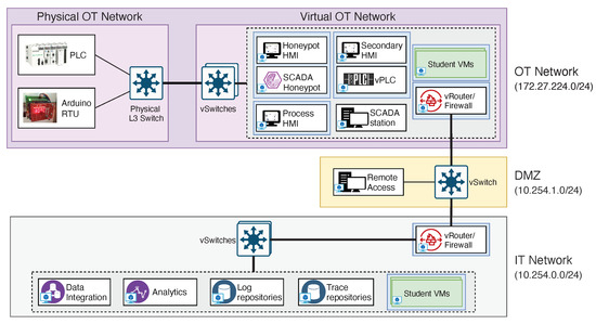
Figure 6. Logical network topology for the full cyber range environment.
A Demilitarized Zone (DMZ) provides isolation between the OT and IT networks, with the latter hosting the logging, data ingestion, normalization and analytics service/component VMs. Components in the IT, DMZ and virtual OT networks are virtualized within a type 1 hypervisor environment, together with the associated network infrastructure, which is supported by means of virtual switches, port groups and network appliance VMs.
CANVAS components may be manually provisioned or instantiated from a template library of assets. This approach allows for efficient reuse of resources with a quick deployment turnaround time, requiring minimal customization for each instance. In the specific case of Figure 6, template-based VMs are enclosed within blue boxes—this is the case for all the HMI VMs, which are created from a base template composed of a Windows 7 OS image and the Rapid SCADA [24] open-source industrial automation platform, or the vPLC, based on a Linux OS image with an OpenPLC deployment. Other available templates include preconfigured Mininet simulated topologies, virtual devices or low interaction honeypots, which can be seamlessly added to the laboratory environment network in order to enrich the scenario.
Students are also provided with template-based VMs (green VMs), preloaded with the Kali Linux OS [25], configured with 2 virtual CPU cores, 2 GB RAM, two network interfaces and 50GB of persistent storage, providing equal resources and access rights for everyone, while shielding the environment from the Campus LAN
Figure 7 depicts the physical topology for the cyber range environment setup. VMs are hosted on VMware ESXi 7.0 hypervisor nodes (both servers share the same configuration) which, besides the student VM instances, also host supporting services and virtualized components required for the specific laboratory environment (such as HMIs or vPLCs). Moreover, note that student VMs have a multi-homed network interface setup. This allows for students to access their VMs via the interface connected to the campus network, using the second interface to access the cyber range scenario. This is the reason for the duplicate representation of the student VMs in Figure 6, since each one is provisioned with two network interfaces, one connected to the OT and the other one to the IT network.
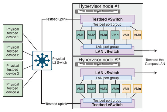
Figure 7. Cyber range environment physical infrastructure (green VMs used for students; yellow VMs support services and testbed components for the specific scenario).
One challenge remains, though. For network traffic capture and analysis purposes, students need to access a SPAN/Mirror port, configured to replicate traffic from selected devices belonging to the physical network side (on the left)—in fact this a recommended practice for Intrusion Detection Systems (IDS) deployment in critical infrastructure scenarios, as it allows for passive traffic capture without introducing a point of failure in the middle of a communications path. Unfortunately, our cyber range setup uses a managed switch that does not support Remote SPAN (RSPAN) or Encapsulated RSPAN (ERSPAN) capabilities [26], therefore limiting the possibility of creating shared mirror ports. With such capabilities in place, VMware distributed vswitches or Open vSwitch [27] instances could have been used as endpoints for traffic replication, effectively allowing for the replication of mirror traffic across all the student VM instances.
While it is possible to bridge a SPAN trunk with an ESXi vswitch, allowing all connected VMs to share the traffic, this setup can only be deployed for a single hypervisor server node, as there are no means to bridge two vswitches in separate hypervisor instances without resorting to distributed vswitches (a solution allowing to forward traffic to other platforms was preferred). To tackle this problem, a mirror port from the physical switch was connected to a hypervisor node vswitch, using an Open vSwitch (OVS) VM instance to daisy chain the traffic to another node (see Figure 8).

Figure 8. Cyber range infrastructure, with shared network mirror support (student VMs in green).
The OVS VM is in charge of bridging traffic between the vswitches that form the virtual network used to distribute the network mirror across the hypervisor nodes (depicted in yellow). To achieve this, the OVS VM has native access to one of the physical network interfaces of the hypervisor node via PCIe passthrough, a technique that takes advantage of I/O Memory Management (IOMMU) capabilities of modern CPUs to directly map PCI physical addresses into the VM virtual memory addresses, bypassing device emulation or paravirtualization. In practical terms, PCIe passthrough allows to natively bind a specific PCIe device to a VM; in our case, this is used to provide the uplink to the mirror vswitch on the next hypervisor node. This approach daisy chains mirror traffic between hypervisor nodes, but it can be also be deployed in star-like topologies and even between server nodes using different hypervisor platforms, providing a platform-neutral approach for sharing of mirror traffic.
The mirror traffic vswitches on each hypervisor node are configured to accept forged MAC addresses, thus accepting frames that not correspond to vswitch port addresses, and to operate in promiscuous mode, allowing all virtual network interfaces connected on the same port group to receive a copy of all the traffic flowing in the switch. This arrangement allows for the injected traffic from the SPAN trunk to be received by all the VMs with a network interface configured on the mirror vswitch port group. Enabling VGT mode (Virtual Guest Tagging) on the vswitch mirror port group, by setting the VLAN ID to 4095, could also be useful in case more than one VLAN ID was carried in the uplink trunk, but this is not the case in this scenario.
With the replicated traffic mirror solution in place, the student VMs were revised to include a third network interface, which allows them to receive a copy of the physical testbed traffic, a useful capability for testing of IDS/IPS techniques or for traffic analysis.
4. Guided Learning, Hands-On: Course Plan and Execution Strategy
This section provides an outline of the action plan that is followed during an introductory course, designed to introduce the subject of SCADA cyber-physical system security. This course was designed for students with basic knowledge about networking technologies and minimal familiarity with BSD or System V UNIX derivative systems. This profile roughly corresponds to a 2nd year BSc student, accordingly to the ACM standard Computer Science or Computer Engineering reference curricular structure, which will have no difficulty in grasping the subjects; however, trainees with a less advanced level of knowledge can easily acquire the fundamental prerequisites within a feasible timeframe. The course plan is organized into three different stages:
Introduction and context: before moving into the main course activities, trainees are introduced to the specific nature of SCADA ICS technologies, concepts and devices, which culminates with the presentation of the cyber range scenario; this introduction also provides the instructors with an opportunity to identify and start addressing the knowledge gaps that may exist within heterogeneous audiences.
Cyber range scouting/reconnaissance: ICS device, host and service enumeration procedures for pentesting and scouting procedures have much in common, in the sense that many IT-specific practices cannot be directly transposed to this domain. In this stage, students are introduced to a basic toolset for network and device scans, being challenged to identify as many devices as possible with minimal disruption.
Attack planning and deployment: this stage is dedicated to offensive procedures, from layer 2/3 floods to the execution of Man-in-The-Middle attacks. These attacks are used to demonstrate potential outcomes that may range from service disruption or interruption (due to device crashes or network resource exhaustion to loss of visibility and/or process awareness.
The evaluation of possible defensive mechanisms is also addressed, but not as in-depth as the other core topics, due to the introductory nature of the course. Next, we detail the various steps undertaken within the training modules/lessons, also presenting the expected outcomes for each one. Moreover, specific hints regarding the didactic strategies adopted for each step are also provided, based on the authors’ experience.
4.1. Introduction and Context
As most trainees come from an IT background, the first step must encompass an effort to bring the group to a similar level of basic knowledge regarding cyber-physical systems and the ICS domain. This initial module was designed to address these issues, being organized as depicted in Figure 9.

Figure 9. Organization of the first training module (6 h).
The adopted strategy starts by introducing the concept of Critical Infrastructure and Essential Services, later moving into the specific details about the kind of Industrial Control Systems supporting these infrastructures. Later on during this stage, trainees are presented to the physical process that is part of the cyber range (presented in Section 3.2), being given access to the HMI and allowed to directly interact with it. This first interaction has proven vital to stimulate curiosity and trainee motivation.
Once the introductory stage of the module is completed, comes the moment to deliver a conceptual and technical introduction of what a SCADA system is, in parallel with a detailed walkaround of the cyber range ICS process—the Purdue Model adopted by IEC 62443 [22] is an important instrument to assist in this task, as it helps categorize the equipment by functional levels within an organizational structure. In this process, students become familiarized with the concept of master station, slave and field devices, also learning about the role performed by PLCs and RTUs.
Regarding the latter point, and because of its relevance within the ICS domain, special care is taken regarding the explanation of how PLCs work and how they are distinct from general-purpose computers: this includes an analysis of the PLC scan cycle (see Figure 10), as well as the concept of cycle time and a quick overview of IEC 61131-3 [28] programming languages.

Figure 10. PLC scan cycle.
Still within the scope of the IEC 61131-3 programming language introduction, trainees are are also put into contact with simple Structured Text (ST) and Ladder Logic (LL) examples (see Figure 11). For this specific purpose, students are put into contact with the OpenPLC project, which is used to provide a containerized PLC runtime and a IDE (OpenPLC Editor) that can be used to experimentation purposes.

Figure 11. Simple example for a Greater-Than (GT) function block: LL vs. ST representations.
Being a crucial part of what makes SCADA systems possible, domain-specific communications protocols are also introduced and discussed. Among them, the Modbus protocol is dissected into detail, not only to provide an insight about the kind of legacy technologies which are still being widely used, but also because this protocol was adopted in the cyber range environment scenario.
The analysis of the Modbus protocol covers aspects such the framing structure (see Figure 12), operation semantics and Function Codes, as well as the data types and addressing modes (Modicon and IEC/Quantum). During the discussion of communications-related topics, instructors also take advantage of the context to review other related aspects such as serial communications or TCP/IP protocol fundamental concepts (such as the three-way handshake or sequence numbers, for instance).

Figure 12. Modbus Application Data Unit (ADU) format.
Experimentation is always encouraged along the progression path; during this stage, a CANVAS ephemeral playground with several OpenPLC VMs is made available, also including some editor-bundled Windows VMs (for students who do not use the Windows OS or do not have resources to run VMs on their own PCs).
4.2. Initial Scouting/Reconnaissance Procedures
Network/range scouting is frequently one of the first stages at the start of pentesting campaigns, but it can also be part of an attack preparation effort. Regardless of the intentions, such efforts are necessary to gather information about the environment, discover and identify topologies, hosts and services. This module was designed to provide an introductory approach to this, being organized as shown on Figure 13.

Figure 13. Organization of the second training module (6.5 h).
A two-way approach is undertaken: First, trainees are encouraged to search for information about the process control network having basically the same level of access they would have by compromising a host on the same segment; on the second stage, access to the network mirror interface will be provided, for traffic capture and analysis and validation of the some of the findings obtained during the first attempt.
At the start of this module, students go trough a quick recap of the fundamental principles behind techniques such as SYN or FIN scans or OS fingerprinting, that be used to get information about OS versions or TCP/IP open ports, also taking advantage of the communications concepts reviewed on the first module. Combined with extra information (as MAC addresses, albeit these are not always trustable and require being on the same Layer 2 domain as the device) or Open-Source Intelligence (OSINT) techniques, it is explained how the information collected from these sources can be further augmented with additional aspects concerning manufacturers and models, as well as firmware versions or known vulnerabilities (the work in [29] is often suggested as reading material in this context). For this reason, vulnerability scanners such as OpenVAS [30] are deliberately avoided in this course, instead encouraging students to engage in research processes.
Once the fundamental probing techniques are reviewed, students are then briefed about the specific limitations of ICS technology. This is a very important step, as people coming from an IT domain with a more solid background might be tempted to apply the knowledge acquired beforehand in a straightforward fashion—for instance, a common pitfall is to resort to vulnerability scanners, executing dangerous scanning routines that can disrupt the operation of an ICS. For this purpose, examples from authoritative sources such as NIST SP800-82 or talks by field experts about incidents caused by pentesting or vulnerability scanning procedures are presented [31], in order to establish a set of golden rules for ICS security operations (see Figure 14).

Figure 14. Good practices for ICS pentesting and scouting procedures.
All the procedures will be undertaken from each one of the students’ VMs, constituting the execution environment for most procedures and tasks. The first thing students will be asked to do is to run a simple tcpdump [32] capture on the network interface connected to the process control network, saving it in a PCAP format for analysis. Findings may be somehow scarce (moreover because we are dealing with switched ethernet network) but nonetheless interesting: Spanning Tree Protocol (STP) Bridge Protocol Data Unit (BPDU) frames, broadcast traffic (mostly ARP requests) and some multicast traffic (such as Multicast Listener Discovery protocol for IPv6, ICMPv6 duplicate frame detection or Simple Service Discovery Protocol traffic). Trainees will be encouraged to review these protocols, trying to infer information about existing hosts (for instance, ARP requests provide valuable insight about the network ranges which are being used on the network segment, as well as the address for potentially existing hosts, and STP PDUs may provide information regarding ports, switches, port priorities and addresses).
The analysis of ARP traffic also serves to show trainees how stealthiness can be easily thwarted by carelessness—a fatal failure for an attacker or during a red team CTF exercise, since an intruder host making or replying to ARP requests may generate unwanted “noise”, leading to its disclosure. To deal with this, students are taught about the Linux arp_ignore and arp_announce sysctl variables [33], and how to use them to reduce/supress ARP traffic.
Once the initial capture analysis in concluded, students progress to the network scanning procedures, using the arpscan [34] and NMAP [35] tools. Both are well-maintained, open-source and portable tools, albeit NMAP has a more complete feature set and a powerful command line interface and scripting capabilities, also being able to integrate with other toolchains.
Students will be asked to scan the entire network range, in order to detect active hosts, and in some cases also using spoofed IP addresses. Moreover, they are reminded about the need to perform a slow scan, because of the specific characteristics of ICS environments, albeit a professional attacker would probably do it anyway, in order to go unnoticed by intrusion detection techniques based on volumetric network traffic analysis. The first attempts are to be undertaken using the arpscan tool (see Figure 15). Trainees will quickly develop an intuition about the trade-off between stealthiness and information gathering potential—for instance, total suppression of the ARP protocol and use of a IP-less network interface may limit the effectiveness of many techniques (for instance, ARP scans will not properly work with total ARP suppression).

Figure 15. ARP scan results.
Afterwards, the NMAP tool will be used to implement a ping scan (see Figure 16), with no DNS reverse resolution; this is a lightweight (albeit not error-proof) way to scan an IP range. Students are also taught to implement SYN and FIN scans, to acquire information about open ports and potentially available network services.

Figure 16. NMAP scan results.
Having access to the same Layer 2 domain as the testbed network (something that, in most cases, would not be possible in the open Internet), students are able to get information about Ethernet MAC addresses, providing extra insights about the nature of the devices found on the network. While extra information could be gathered from the devices using NMAP’s OS detection feature, this is ill-advised; this feature works by using TCP/IP stack fingerprinting techniques, sending a series of TCP and UDP packets to the target and gathering evidence about features such as response patterns, TCP Initial Sequence Numbers, initial window sizes, protocol options support, TOS fields or IP ID (for the MDL period) predictability, among others. Overall, it is too dangerous, considering the sensitive nature of many device TCP/IP stacks.
The use of device-specific NMAP scripts (such as the modicon-info.nse [36] script) and tools such as smod [37] (a Modbus penetration testing framework) are also used to complete the device profiling effort (see Figure 17). Moreover, students are not told about the existence of a SCADA honeypot; this device appears legitimate at a first glance, requiring further effort to be identified as such.

Figure 17. NMAP results for the modicon-info.nse script executed against the Schneider M340 PLC.
Once the active scanning procedure is finished, the mirror interfaces will be activated, allowing trainees to get a copy of the testbed network traffic. The analysis of this traffic will reveal/confirm many findings, namely, the IP and MAC addresses of the M340 PLC, the location of the HMI and SCADA stations and some potential insights about the Arduino-based RTU needs to be analyzed with special attention.
While the PLCs and HMIs exhibit a traffic signature which is expected from a regular Modbus polling cycle, the Arduino-based RTU exhibits an unusual pattern in terms of ARP requests and TCP/IP traffic, with a MAC address prefix that seems very unlikely for this kind of hardware. The reasons for this are deeply rooted in the nature of the Wiznet W5100 network interface Application-Specific Integrated Circuit (ASIC), as well as in the limitations of a simple microcontroller, on which the Arduino is based upon. Thus, instructors provide a series of clues (Wiznet W5100 ASIC datasheets [20], discussion about the Arduino Modbus library implementation) which are expected to lead students to find an answer for the unusual patterns.
During this module, and according with the background and skill level of the course attendees, instructors are advised to fill eventual knowledge gaps (for instance reviewing TCP/IP connection state diagrams or other required technical concepts), also encouraging (and giving time for) students to explore these concepts on their own. For student groups with a more advanced skillset, this step offers an interesting opportunity to explore OSINT techniques, which may be leveraged by students to make the most of the information that was gathered. Trainees are encouraged to work in groups (in some cases formed by the instructors’ initiative, to balance skill levels), having to work autonomously at the end of the module to deliver a complete report about the findings.
4.3. Attack Planning and Deployment
This constitutes the final course module, being structured around a “what if?” perspective on attack execution and outcome analysis (see Figure 18). Instead of focusing on providing theoretical knowledge about attack techniques, trainees are allowed to execute attacks by themselves and observe the results. For this purpose, the CANVAS framework constitutes an ideal platform, as it was designed for easy recoverability in case of failure. This is further reinforced by the existence of Out-of-Band management mechanisms, as well as the introduction of STONITH (an acronym for Shoot The Other Node In The Head, a term commonly used in active-passive cluster setups to designate remotely controlled power sockets that allow to cut off the power or power cycle a specific node) modules the allow to remotely cycle or power up any device in the physical process testbed.

Figure 18. Organization of the third training module (5.5 h).
This module starts with a review of the classic Layer 2/3 attack flooding techniques. While experience acquired from the IT field may have provided trainees with an intuition about the effects of targeting a specific network node, both in terms of network performance or communications/service degradation, the effects on ICS automation devices may be more radical, causing resource exhaustion or even equipment crashes. The fundamental principles behind most of the attacks hereby described are documented in past work from the authors [38], which is also suggested as reading material.
To properly understand the potential effects of the aforementioned flooding attacks, students are introduced to the hping3 [39] tool, which is used to generate ICMP, SYN or UDP floods against cyber range nodes, using combinations of different transmission rates, spoofed source addresses (or even random source IPs), specific TCP flags, variable payload sizes and large windows. The nping [40] tool is also used for similar purposes, with other attack profiles also being tested (such as Smurf or Land attacks [41]).
Once attacks start, students are asked to check both the traffic mirror interface and the physical process HMI to analyze and observe the attack effects. Quite often, traffic floods are enough to blind the HMI (see Figure 19), causing loss of process visibility due to communications channel exhaustion, or even device unavailability. The latter case may be triggered quite easily due to the fact the M340 PLC tends to crash and become permanently unavailable (until the next power cycle) due to weaknesses in the TCP/IP stack implemented in the specific firmware version in use.

Figure 19. SYN flood effect on the SCADA system.
Besides layer 2/3, layer 7 flooding attacks are also analyzed, with a special focus on Modbus API abuse through means of variable frequency read and write operations (using the smod tool or the metasploit modbusclient [42] module). Due to the lack of authentication of access control mechanisms, Modbus devices are often vulnerable to these sort of attacks, with unpredictable results. Moreover, and for similar reasons (lack of authentication), Metasploit can also be used to download the project running on M340 PLCs, by using the modicon_stux_transfer [43] module.
The next stage is dedicated to the review of the ARP protocol. The protocol state machine is analyzed, with a main concern in mind: bring to evidence its stateless nature, as well as the absence of security mechanisms, something that can be traced back to its roots. This step is also valuable to familiarize the trainees with the main vulnerabilities which are implicit to the protocol design, namely, the possibility of abusing it to deploy a MiTM attack (see Figure 20). Such attacks can be used both as part of a scouting procedure (to better understand the nature of the communications between nodes) or to corrupt in-flight process data, by manipulating Modbus ADUs.

Figure 20. ARP poisoning-based MiTM attack.
For this purpose, trainees are introduced to the ettercap [44] and bettercap [45] tools, which are used to prepare and deploy the ARP MiTM attacks. After a short briefing on the tools and their usage, students are instructed to prepare a first campaign targeting the HMI and M340 PLC, in order to better grasp the relevance of such attacks. The first objective is focused on deploying a successful MiTM, using the mediator role of the attacker node (which will be the students’ VM) to capture traffic (see Figure 21).
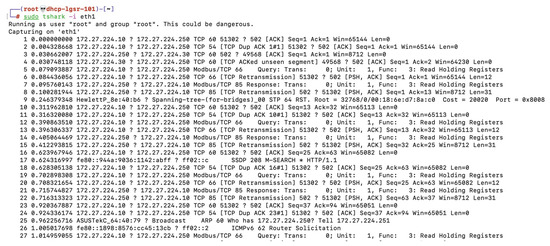
Figure 21. Traffic sniffing during ARP MiTM session.
Once the capture is acquired, trainees are asked to analyze its contents, searching for relevant patterns. Despite the fact that the mirror interface would already provide this information, there is an explicit intention of showing of such an attack can provide the means to effectively capture traffic for scouting purposes. For this purpose, the Wireshark [46] tool is used, in order to follow the network trace flows, using its filtering and dissector capabilities to easily decode Modbus ADUs (see Figure 22).

Figure 22. Trace analysis using wireshark.
Using an approach similar to the approaches followed by possible attackers, trainees are expected to find the Modbus holding registers within the ADUs, which provide the information periodically requested by the HMI. Once this information is acquired, students are ready for the offensive MiTM stage.
Weaponizing the ARP MiTM requires the capability for manipulating in-flight packet data. Despite the fact that frameworks such as Scapy [47] are particularly apt for this purpose, the learning curve might not be compatible with the scope of an introductory course. For this reason, the authors have opted instead to use the built-in ettercap scripting capabilities, by means of etterfilter. Ettercap filters get the implicit benefits from the ettercap tool, which handles traffic forwarding at the attacker node, also taking care of checksum recalculation when packet payloads are changed. Trainees are introduced to the etterfilter syntax, being encouraged to experiment with scripts of their own. The obvious next step will be to inject fake state information into the HMI, using an ARP MiTM (see Figure 23).

Figure 23. Injection of fake data into the HMI (byte offset deliberately hidden).
For this purpose, students are asked to leverage what they learned about the Modbus ADU format, together with the information acquired from the testbed traffic captures, the deployment of ARP MiTM attacks, as well as etterfilter syntax to plan and execute an offensive MiTM, with the purpose of injecting false temperature data into the HMI. This attack is particularly interesting as part of an offensive strategy: for instance, an attacker might use it to blind the HMI, allowing him to directly manipulate process data while going unnoticed to the SCADA system operators.
Moreover, students are also encouraged to try the same approach on other hosts, eventually discovering some particularly curious features about the cyber range; for instance, the Arduino-based RTU exhibits some sort of resilience towards this sort of attack, which can be explained by the same reasons that prompted the instructors to ask students to find an explanation to the unusual traffic patterns involving this device, during the development of the second course module.
This module finishes with a discussion of the potential countermeasures that could be put into place to defend from these attacks, with an historical review of several related proposals (such as TCP syncookies), as well as the presentation of several techniques and technologies that can be used for avoidance or mitigation purposes, such as whitelisting, port security, passive monitoring, and so on.
4.4. Final Considerations and Notes about the Course Development Strategy
The number of training hours outlined in the diagrams at the beginning of each training module subsection corresponds to synchronous (class) time. While the course structure is organized along a total of 18 h, note that trainees are expected to spend at least the same amount of time on individual out-of-class work. This is crucial for both knowledge consolidation and development of trainee autonomy.
Furthermore, note that the guided learning strategy that was adopted, which is focused on a hands-on approach, steers as much as possible away from creating dependency on the instructors, instead encouraging students to work as autonomously as possible. Instructors are not regarded as traditional schoolmasters, in the sense that their role is not to impose a specific learning style, but rather help trainees reach the goal of grasping the important concepts, while respecting as much as possible the particular students’ profile. For this reason, instructors are encouraged to strive for accessibility but also to profile trainees as quickly as possible in the early course stages, in order to be able to propose self-study material and strategies to help the less-experienced acquiring the minimum prerequisites. Instructors should not stand in the way of students with willpower, but rather provide them the means to turn commitment into results.
Finally, there is the question of assessing the validity of the knowledge acquired by trainees. This is undertaken by resorting to both individual and group-centric synchronous/ongoing evaluation strategies, as well as discrete checkpoints. For instance, the evidence for the students’ proficiency regarding the first training module contents is undertaken during classes (synchronously), with students also being assigned with developing a small group project (a PLC program) to perform a specific task. For the second module, synchronous (during class) evaluation is also undertaken, with students being asked to further explore the cyber range on their own and produce a report detailing their findings. The third module is also evaluated using an hybrid approach: synchronous evaluation, together with a group project focused on further exploiting and reporting any relevant vulnerabilities, which must also include a proposal to correct and mitigate the weaknesses and vulnerabilities that were found. The course is concluded with an open book written exam accounting for 50% of the final grade.
5. Feedback and Results
Even though a full-blown methodical study on the impact of the described training strategy is outside the scope of this paper, the students’ feedback has been regularly acquired and indicates positive results, as presented and discussed next.
First of all, note that both the cyber range and the course structure hereby presented have been developed and put into practice over the past 3 years in the scope of a subject (“Conception and Development of Secure Infrastructures”) that is part of the curricular plan of the MSc on Computer Security taught at the Department of Informatics Engineering of the University of Coimbra (PT).
As part of the ongoing assessment procedures integrated within the pedagogical quality monitoring system of the University of Coimbra, students are regularly polled about their perception on professor and course performance. These inquiries are focused on a series of quantitative indicators (measured on a Likert scale, from 1 to 5), which include aspects such as the perception about their own learning outcomes, the effectiveness of the applied methods and the relevance of the course contents, among all. This specific course has fared consistently above the course subject average over the past 3 years (See Figure 24), with a contained distribution in terms of the score range. Overall scores are between the 90 and 95% percentile across the departmental course offer.
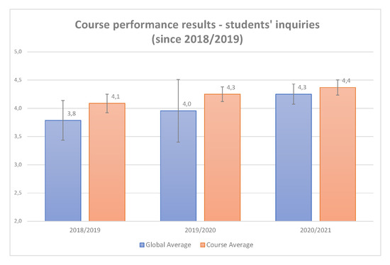
Figure 24. Students’ inquiries results.
While not being possible to publish the result for all inquiry questions, Figure 25 depicts an overview of the results for the main items that were common among the evaluation forms created for each semester since 2018/2019, both for this course and for the global MSc course average. These results illustrate to which extent trainees have a perception about the benefits of the proposed training approach.

Figure 25. Students’ inquiries results—detailed.
Even considering the effects of the Covid pandemic, which have been felt over the past two scholar years, the flexibility provided by CANVAS allowed the instructors to deliver the course remotely, with little difference regarding the traditional teaching approach. In fact, the course even improved its performance scores over this period, regarding several indicators.
Finally, it should be said that direct feedback (and also non-quantitative inquiry results) has consistently demonstrated that students appreciate the hands-on approach, considering the firing range as an extremely valuable tool, enabling them the possibility of working on a safe ground, while still providing the means to interact with a high-fidelity scenario.
6. Conclusions and Future Work
This work documents both the design of a cyber range and a cybersecurity training module based on it. More than a conventional piece of academic writing, this paper intends to provide a comprehensive guide about the way authors approached the challenge of introducing students to ICS cybersecurity using a hands-on approach.
The first part of this paper was dedicated to the course support infrastructure. The CANVAS framework was presented, as well as the cyber range environment that was built on top of it. This cyber range is based on a SCADA ICS scenario developed around a process use case chosen according to a set of specific criteria, namely: relevance; an adequate complexity/functionality balance; provide intersections with areas akin to different cybersecurity practitioner profiles.
The second part of this paper is devoted to the development of the course plan. Structured along three modules, the course plan was conceived to provide students with functional knowledge and skills on the topic of ICS cyber-security. By pursuing a hands-on approach, students were thoroughly guided along a natural progression path, adapting contents and strategies accordingly to the different backgrounds and skill sets.
Finally, it should be noted that the authors have put the plan herein presented into practice on several occasions, including classes and training sessions, with great success and positive feedback from students, the latter of which has been instrumental in the continuous improvement of the didactic approach.
