JumperlessV5
The next generation jumperless breadboard
0
Project description
Jumperless V5 – 소프트웨어 정의 브레드보드 기반 프로그래머블 하드웨어 플랫폼
프로젝트 소개
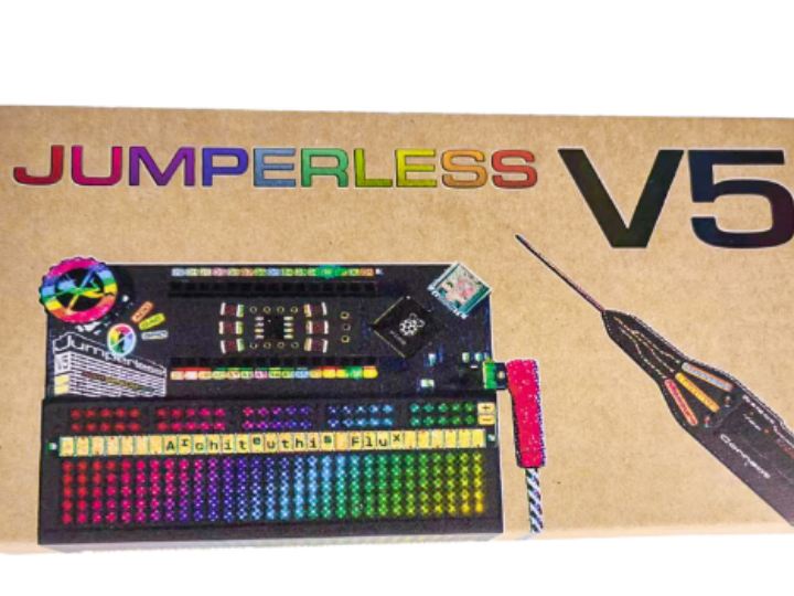
Jumperless V5는 기존 브레드보드에서 사용하던 점퍼선을 소프트웨어로 제어되는 전기적 연결로 대체한 오픈소스 프로그래머블 브레드보드입니다.
일반적인 브레드보드는 사용자가 직접 점퍼선을 연결하여 회로를 구성해야 하지만, Jumperless V5는 내부의 아날로그 스위칭 매트릭스를 이용해 원하는 노드 사이의 연결을 소프트웨어로 설정할 수 있습니다.
메인 MCU로는 Raspberry Pi RP2350B를 사용하며, 회로 연결 제어뿐만 아니라 측정, 전원 제어, GPIO 및 여러 통신 인터페이스를 하나의 플랫폼에서 다룰 수 있도록 설계되었습니다.
단순한 브레드보드라기보다 브레드보드, 개발 보드, 계측 장비, 프로그래머블 전원 공급 장치 등을 하나의 시스템으로 통합한 Hardware IDE에 가까운 프로젝트입니다.
Software-Defined Breadboard
Jumperless V5의 가장 큰 특징은 물리적인 회로 연결 자체를 소프트웨어로 변경할 수 있다는 점입니다.
기존 브레드보드에서는 회로를 수정하려면 점퍼선을 직접 제거하거나 다시 연결해야 합니다.
반면 Jumperless V5에서는 내부의 Analog Crosspoint Switch Matrix를 이용해 브레드보드의 각 노드, GPIO, 측정 채널, 전원 레일 등을 프로그램으로 연결할 수 있습니다.
따라서 기존의 개발 과정이
회로 설계 → 직접 배선 → 측정 → 배선 수정
이었다면, Jumperless V5에서는
회로 설계 → Software Routing → 측정 → 자동 회로 재구성
형태로 변경됩니다.
연결 상태를 소프트웨어에서 관리할 수 있기 때문에 동일한 회로를 다시 불러오거나, 테스트 조건에 따라 연결을 자동으로 변경하는 것도 가능합니다.
통합 측정 및 디버깅 기능
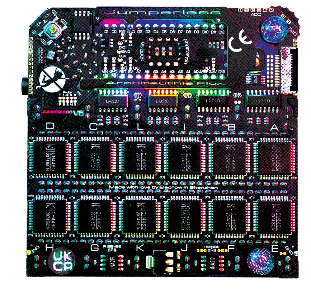
Jumperless V5는 단순히 점퍼선을 전자적으로 대체한 장치는 아닙니다.
일반적인 하드웨어 개발 환경에서 별도의 장비로 사용되는 여러 기능을 보드 내부에 통합하고 있습니다.
주요 기능은 다음과 같습니다.
- 4개의 독립적인 ±8 V 프로그래머블 전원 공급 장치
- 전압, 전류 및 저항 측정 기능
- 10개의 Routable GPIO
- ADC 및 DAC 기능
- UART, I²C, SPI 신호 라우팅
- 원하는 노드를 선택해 측정할 수 있는 Programmable Probe
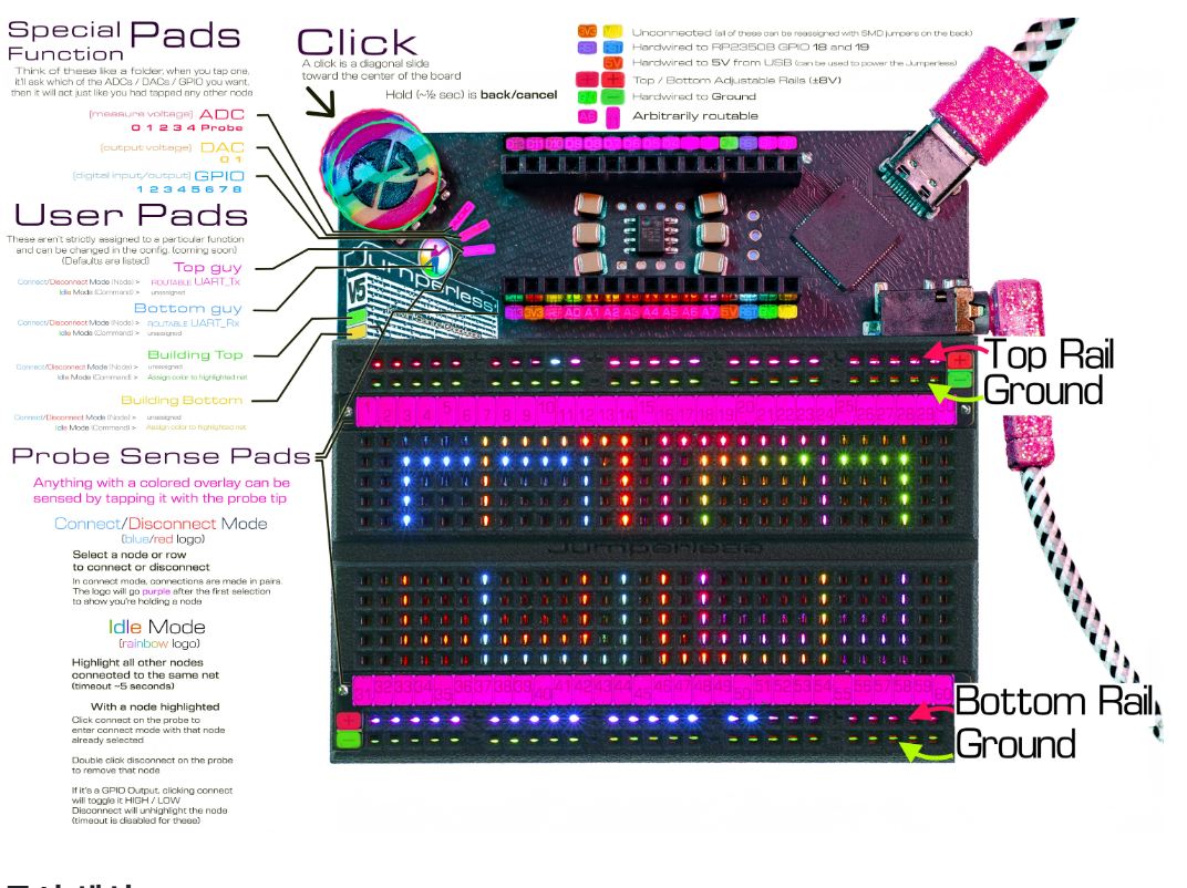
- 브레드보드 하단의 RGB LED를 이용한 연결 상태 시각화
특히 브레드보드 아래에 배치된 RGB LED를 통해 어떤 노드가 연결되어 있는지 시각적으로 확인할 수 있습니다.
복잡한 점퍼선을 직접 따라가야 하는 기존 브레드보드와 달리 회로의 연결 상태를 직관적으로 확인할 수 있어 프로토타이핑과 디버깅에 유용합니다.
RP2350B 기반 프로그래머블 하드웨어 환경
Jumperless V5의 메인 프로세서는 RP2350B입니다.
RP2350B는 라우팅 시스템뿐만 아니라 사용자 인터페이스, GPIO, 측정 장치 및 주변 인터페이스를 제어합니다.
또한 Jumperless V5에서는 스크립트를 이용하여 회로 연결이나 측정 과정을 자동화할 수 있기 때문에 단순한 수동 회로 실험뿐만 아니라 Automated Hardware Testing 환경으로도 활용할 수 있습니다.
예를 들어 다음과 같은 과정을 자동으로 수행할 수 있습니다.
회로 연결 설정
→ 전원 공급
→ 신호 입력
→ 전압/전류 측정
→ 연결 변경
→ 다시 측정
따라서 부품 테스트, 회로 특성 측정, 교육용 전자 실험 및 자동화된 하드웨어 검증 시스템 등에 활용할 수 있습니다.
Wokwi와 실제 하드웨어의 연결
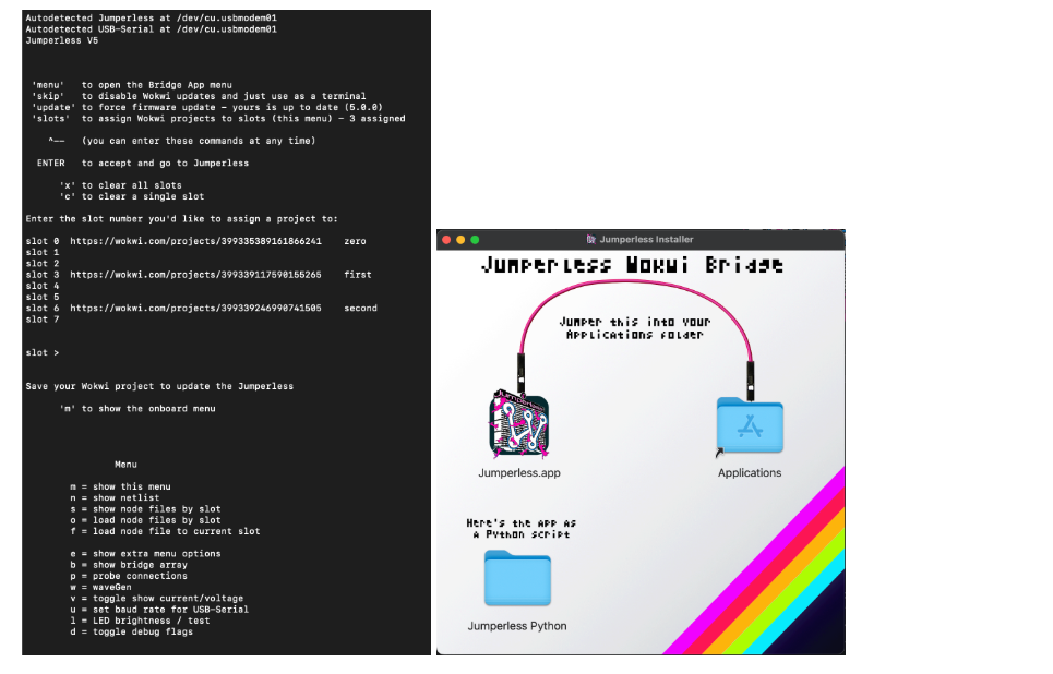
Jumperless V5는 온라인 전자회로 시뮬레이터인 Wokwi와도 연동할 수 있습니다.
Wokwi에서 구성한 회로 프로젝트를 Jumperless 환경에서 활용하여 소프트웨어에서 설계한 회로를 실제 하드웨어 연결로 구현할 수 있습니다.
이를 통해 다음과 같은 흐름이 가능합니다.
Wokwi Circuit Design
→ Jumperless Application
→ Software-Defined Routing
→ Physical Circuit
즉, 온라인에서 회로를 설계한 뒤 실제 브레드보드에 점퍼선을 일일이 연결하는 과정 없이 물리적인 회로로 구성할 수 있습니다.
이는 Digital Circuit Design과 Physical Prototyping 사이의 간격을 줄이는 방식이라고 볼 수 있습니다.
WIZnet Ethernet 지원
W5500,W5100,W6100을 추가할 경우 Jumperless의 기존 회로 제어 및 측정 기능을 유선 Ethernet 네트워크와 직접 연결할 수 있습니다.
이를 통해 USB로 연결된 Host PC에 의존하는 구조에서 벗어나 서버와 직접 통신하거나 테스트 결과를 네트워크로 전송하고, 여러 Jumperless 장비를 중앙에서 관리하는 시스템으로 확장할 수 있습니다.
특히 안정적인 유선 통신이 필요한 자동화 테스트 환경이나 Remote Hardware Lab에서 활용 가능성이 있습니다.

Jumperless V5는 기존에도 USB를 통해 PC에서 회로 구성과 테스트를 제어할 수 있습니다. W5500,W5100,W6100 Ethernet을 추가하면 별도의 USB Host PC에 의존하지 않고 네트워크에 직접 연결되는 형태로 확장할 수 있어, 서버 기반 제어 및 다수 장비의 중앙 관리에 유리합니다.
W5500 Pin Mapping and SPI Configuration
Jumperless V5의 GPIO_1~GPIO_4는 RP2350B의 GPIO20~GPIO23에 연결되어 있으며, 이 핀들은 SPI0의 RX, CSn, SCK, TX 기능으로 사용할 수 있습니다.
따라서 W5500은 다음과 같이 연결할 수 있습니다.
| W5500 | Jumperless V5 | RP2350B | SPI Function |
|---|---|---|---|
| MISO | GPIO_1 | GPIO20 | SPI0 RX |
| SCS | GPIO_2 | GPIO21 | SPI0 CSn |
| SCLK | GPIO_3 | GPIO22 | SPI0 SCK |
| MOSI | GPIO_4 | GPIO23 | SPI0 TX |
| 3V3 | SUPPLY_3V3 | 3.3 V | Power |
| GND | GND | GND | Ground |
Jumperless V5에서는 GPIO와 전원 채널을 Software-Defined Routing을 통해 breadboard의 원하는 위치로 연결할 수 있으므로, W5500 모듈을 breadboard에 장착한 후 위 신호들을 소프트웨어로 해당 위치에 라우팅하는 방식으로 구성할 수 있습니다. Jumperless V5의 공식 설명에서도 GPIO와 전원·측정 채널을 breadboard의 원하는 위치에 연결할 수 있다고 설명합니다.
Arduino-Pico의 lwIP_w5500 드라이버는 기본적으로 4 MHz SPI clock을 사용하며, setSPISpeed()를 이용해 변경할 수 있습니다. 따라서 처음에는 4 MHz로 시작하고, 연결이 불안정한 경우 속도를 낮추거나 안정성이 확인된 이후 더 높은 속도를 시험하는 방법을 사용할 수 있습니다.
Example W5500 Code
Jumperless V5는 Arduino-Pico 기반 펌웨어를 사용하므로, Arduino-Pico에 포함된 W5500lwIP 라이브러리를 이용할 수 있습니다.
Arduino-Pico는 W5500을 공식적으로 지원하며, 기존 WiFiClient, WiFiServer, WebServer, HTTPClient 등의 네트워크 API를 Wired Ethernet에서도 사용할 수 있습니다.
아래 코드는 Jumperless V5의 GPIO_1~GPIO_4를 SPI0로 설정하고, W5500을 통해 간단한 HTTP 서버를 실행하는 예제입니다.
#include <SPI.h>
#include <W5500lwIP.h>
#include <WebServer.h>

// Jumperless V5 GPIO mapping
// GPIO_1 -> RP2350B GPIO20
// GPIO_2 -> RP2350B GPIO21
// GPIO_3 -> RP2350B GPIO22
// GPIO_4 -> RP2350B GPIO23

#define W5500_MISO 20
#define W5500_CS   21
#define W5500_SCK  22
#define W5500_MOSI 23

Wiznet5500lwIP eth(W5500_CS);

WebServer server(80);

void handleRoot()
{
    server.send(
        200,
        "text/plain",
        "Jumperless V5 + W5500\n"
        "Ethernet connection OK\n"
        "Remote Hardware Lab Demo\n"
    );
}

void setup()
{
    Serial.begin(115200);

    // Configure RP2350B SPI0 pins
    SPI.setRX(W5500_MISO);
    SPI.setCS(W5500_CS);
    SPI.setSCK(W5500_SCK);
    SPI.setTX(W5500_MOSI);

    // Start with 4 MHz SPI clock
    eth.setSPISpeed(4000000);

    Serial.println("Starting W5500...");

    if (!eth.begin()) {
        Serial.println("W5500 initialization failed");
        while (1) {
            delay(1000);
        }
    }

    while (!eth.connected()) {
        Serial.print(".");
        delay(500);
    }

    Serial.println();
    Serial.println("W5500 connected");

    Serial.print("IP address: ");
    Serial.println(eth.localIP());

    server.on("/", handleRoot);
    server.begin();

    Serial.println("HTTP server started");
}

void loop()
{
    server.handleClient();
}
Arduino-Pico의 Wired Ethernet 구현은 기본적으로 polling 방식으로 동작하므로, 기본적인 테스트에서는 W5500의 INT 핀 없이도 사용할 수 있습니다.
이 코드는 실제 Jumperless V5 + W5500에서 측정된 결과가 아니라, 사용자가 구성을 재현하기 위한 example sketch입니다.
실제 프로젝트에 적용할 경우 이 코드를 별도의 w5500-demo branch 또는 GitHub Gist로 공개하면 다른 사용자가 동일한 구성을 쉽게 재현할 수 있습니다.
How to Verify the Connection
코드를 업로드하고 W5500을 DHCP를 사용할 수 있는 Ethernet 네트워크에 연결하면, 먼저 Serial Monitor에서 연결 상태를 확인할 수 있습니다.
정상적으로 연결되었다면 다음과 같은 형식의 메시지가 표시됩니다.
Starting W5500...
W5500 connected
IP address: <DHCP assigned IP>
HTTP server started
예를 들어 네트워크에서 192.168.0.32라는 주소가 할당되었다면 같은 네트워크의 PC에서 다음 명령을 실행할 수 있습니다.
curl http://192.168.0.32
HTTP 서버가 정상적으로 동작한다면 다음과 같은 응답을 확인할 수 있습니다.
Jumperless V5 + W5500
Ethernet connection OK
Remote Hardware Lab Demo
또는 PC의 웹 브라우저에서
http://<Jumperless IP Address>
로 접속하여 동일한 결과를 확인할 수 있습니다.
Note: 위 IP 주소와 출력은 실제 측정 결과가 아니라 사용자가 테스트할 때 확인할 수 있는 Expected Result Example입니다. 실제 테스트에서는 DHCP를 통해 할당된 IP 주소를 사용해야 합니다.
What Does This Demo Show?
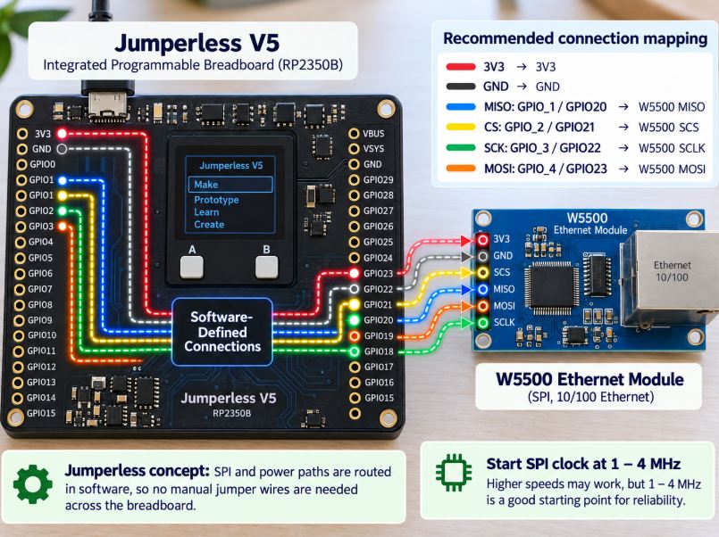
이 데모의 목적은 단순히 W5500을 Jumperless V5에 추가하는 것이 아니라, Jumperless의 Software-Defined Hardware 환경을 Ethernet 네트워크까지 확장할 수 있음을 보여주는 것입니다.
기본 구조는 다음과 같습니다.
Jumperless Breadboard Circuit
→ Software-Defined Routing
→ RP2350B SPI
→ W5500
→ Ethernet
→ Remote PC / Browser
첫 번째 단계에서는 HTTP 요청에 간단한 메시지를 반환하는 것으로 Ethernet 연결을 확인할 수 있습니다.
이후 Jumperless V5의 voltage 또는 ADC measurement 결과를 HTTP 응답에 포함하도록 확장하면,
Physical Circuit
→ Jumperless Measurement
→ W5500 Ethernet
→ Remote PC
구조를 만들 수 있습니다.
즉, 사용자가 직접 breadboard 앞에 있지 않아도 네트워크를 통해 회로의 측정 결과를 확인하는 Remote Hardware Lab의 최소 구현으로 확장할 수 있습니다.
Jumperless V5는 원래 회로의 연결과 측정을 소프트웨어로 제어할 수 있다는 특징을 가지고 있기 때문에, W5500을 추가하면 이러한 Software-Defined Prototyping 환경에 유선 네트워크 접근 기능을 추가하는 형태가 됩니다.
Network-Connected Hardware Lab으로의 확장
Jumperless V5의 특징은 단순히 회로를 자동으로 연결해주는 것에 그치지 않습니다.
W5500과 같은 Ethernet Controller를 활용하면 네트워크를 통해 원격에서 회로를 설정하거나 테스트 결과를 전달하는 형태로 확장할 수 있습니다.
예를 들어 다음과 같은 Application을 생각할 수 있습니다.
Remote Hardware Lab
사용자가 원격 PC에서 회로 설정을 전달하면 Jumperless가 실제 회로 연결을 변경하고 측정 결과를 다시 네트워크로 전송할 수 있습니다.
또한 여러 테스트 조건을 서버에서 전달하여 회로를 자동으로 변경하고 측정하는 Automated Hardware Test System으로도 활용할 수 있습니다.
이 경우 Jumperless의 Software-Defined Hardware 개념과 WIZnet의 Ethernet 기능을 결합하여 다음과 같은 구조를 만들 수 있습니다.
**Software-Defined Breadboard
- Wired Ethernet
= Network-Connected Programmable Hardware Platform**
Open Hardware Design
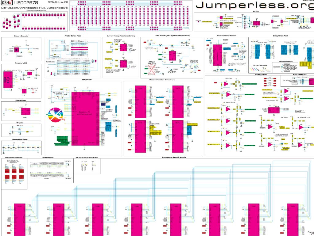
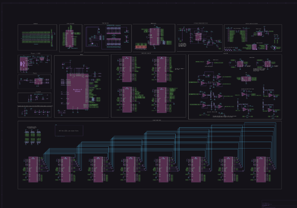
Jumperless V5는 하드웨어와 소프트웨어가 공개되어 있는 오픈소스 프로젝트입니다.
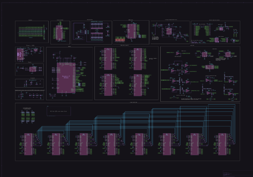
GitHub Repository에는 펌웨어뿐 아니라 PCB 및 하드웨어 관련 자료가 공개되어 있어 전체 시스템의 구조를 확인하거나 필요에 따라 수정할 수 있습니다.
이러한 구조 덕분에 완제품을 사용하는 것에 그치지 않고 새로운 인터페이스나 통신 기능을 추가하여 다양한 Application으로 확장할 수 있습니다.
Conclusion
Jumperless V5는 기존 브레드보드의 물리적인 점퍼선을 Software-Defined Electrical Connection으로 변경한 독특한 하드웨어 프로토타이핑 플랫폼입니다.
RP2350B, Analog Crosspoint Switching, Programmable Power Supply, 측정 기능, RGB Visualization, Wokwi Integration 등을 하나의 시스템에 결합하여 기존 브레드보드와는 다른 개발 환경을 제공합니다.
WIZnet Ethernet은 프로젝트에 아직 통합되어 있지 않지만, 라우팅 가능한 GPIO 8개가 RP2350B의 하드웨어 SPI0/SPI1 핀과 그대로 겹친다는 점에서 W5500 등을 연결해 볼 만한 확장 지점을 제공합니다. 이 경로가 실제로 검증되면 Jumperless V5는 단순한 Software-Defined Breadboard를 넘어
Remote Hardware Lab → Automated Hardware Testing → Network-Connected Prototyping Platform
과 같은 분야로 확장할 수 있는 프로젝트입니다.
Jumperless V5 – Software-Defined Breadboard for Programmable Hardware Prototyping
Introduction
Jumperless V5 is an open-source programmable breadboard designed to replace traditional jumper wires with software-controlled electrical connections.
Instead of manually wiring each point on a breadboard, Jumperless V5 uses a matrix of analog crosspoint switches to dynamically connect different nodes under software control. The project describes this concept as a kind of hardware IDE, combining a breadboard, development board, programmable power supply, measurement equipment, and debugging tools into a single platform.
The main controller is the Raspberry Pi RP2350B, which manages the routing system, user interface, measurement functions, and programmable hardware environment.
Software-Defined Breadboard
The key idea behind Jumperless V5 is that the physical circuit itself becomes programmable.
On a traditional breadboard, changing a circuit requires manually removing and reconnecting jumper wires. Jumperless V5 instead controls the electrical paths through an analog switching matrix.
This allows connections between breadboard rows, GPIO, measurement channels, and power rails to be changed automatically by software. The routing configuration can also be stored as a human-readable netlist and loaded again later.
For example, a circuit connection can be described in software and the routing system automatically determines the physical path through the switch matrix.
This changes the traditional workflow from:
Design → Manually Wire → Measure → Modify Wiring
to:
Design → Software Routing → Measure → Automatically Reconfigure
The result is a much more programmable and repeatable hardware development environment.
Integrated Measurement and Debugging
Jumperless V5 is more than an electronically controlled breadboard.
The board integrates several functions normally provided by separate pieces of laboratory equipment.
It provides:
Four independently programmable ±8 V power supplies
Multiple voltage, current, and resistance measurement channels
Ten routable GPIO channels
ADC and DAC functions
UART, I²C, and SPI signal routing
A programmable probe for selecting and measuring circuit nodes
Hundreds of RGB LEDs underneath the breadboard
The RGB LEDs visualize circuit states directly underneath each connection point, helping users understand where signals and connections are located without tracing a large number of physical jumper wires.
The routing matrix can also reconfigure connections in less than a few milliseconds, allowing circuits and measurement points to be dynamically changed while the system is operating.
RP2350B and Programmable Hardware Environment
Jumperless V5 uses the RP2350B as its main processor.
One of the important features of the platform is that hardware configuration itself can be controlled programmatically. The board supports an onboard Python environment, allowing scripts to configure power supplies, create connections, perform measurements, and communicate with external devices.
This makes it possible to automate tasks such as:
Circuit configuration
→ Signal generation
→ Voltage/current measurement
→ Circuit modification
→ Measurement again
Such a workflow could be useful for automated component testing, hardware education, circuit characterization, and rapid experimentation.
Wokwi and Digital-to-Physical Prototyping
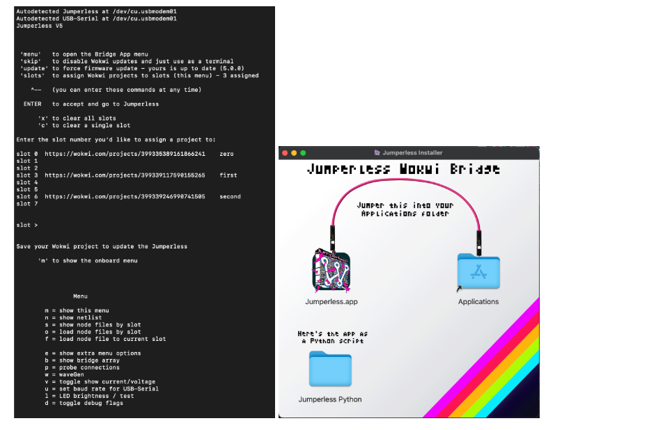
Jumperless V5 also integrates with Wokwi, an online electronics simulator.
Multiple Wokwi projects can be assigned to slots in the Jumperless desktop application. When a circuit configuration is changed, the corresponding configuration can be transferred to the physical Jumperless hardware.
This creates an interesting bridge between virtual circuit design and physical prototyping:
Wokwi Circuit Design
→ Jumperless Application
→ Software-Defined Routing
→ Physical Circuit
The approach reduces the gap between circuit simulation and real hardware testing.
W5500 Pin Mapping and SPI Configuration
Jumperless V5 GPIO_1 through GPIO_4 are connected to RP2350B GPIO20 through GPIO23, and these pins can be used as SPI0 RX, CSn, SCK, and TX.
Therefore, the W5500 can be connected as follows.
| W5500 | Jumperless V5 | RP2350B | SPI Function |
|---|---|---|---|
| MISO | GPIO_1 | GPIO20 | SPI0 RX |
| SCS | GPIO_2 | GPIO21 | SPI0 CSn |
| SCLK | GPIO_3 | GPIO22 | SPI0 SCK |
| MOSI | GPIO_4 | GPIO23 | SPI0 TX |
| 3V3 | SUPPLY_3V3 | 3.3 V | Power |
| GND | GND | GND | Ground |
Jumperless V5 allows GPIO and power channels to be connected to any position on the breadboard through Software-Defined Routing. This means that a W5500 module can be placed on the breadboard and the SPI signals above can be routed to the required positions through software.
The official Jumperless V5 documentation also describes how GPIO, power, and measurement channels can be connected to arbitrary locations on the breadboard.
The Arduino-Pico lwIP_w5500 driver uses a 4 MHz SPI clock by default, and the SPI speed can be changed using setSPISpeed().
For an initial test, users can start at 4 MHz. If the connection is unstable, the SPI clock can be reduced, or higher clock speeds can be tested after stable operation has been confirmed.
Example W5500 Code
Jumperless V5 uses an Arduino-Pico-based firmware environment, so the W5500lwIP library included with Arduino-Pico can be used.
Arduino-Pico officially supports the W5500 and allows existing networking APIs such as WiFiClient, WiFiServer, WebServer, and HTTPClient to be used with wired Ethernet.
The following example configures Jumperless V5 GPIO_1 through GPIO_4 as SPI0 pins and starts a simple HTTP server through the W5500.
#include <SPI.h>
#include <W5500lwIP.h>
#include <WebServer.h>

// Jumperless V5 GPIO mapping
// GPIO_1 -> RP2350B GPIO20
// GPIO_2 -> RP2350B GPIO21
// GPIO_3 -> RP2350B GPIO22
// GPIO_4 -> RP2350B GPIO23

#define W5500_MISO 20
#define W5500_CS   21
#define W5500_SCK  22
#define W5500_MOSI 23

Wiznet5500lwIP eth(W5500_CS);

WebServer server(80);

void handleRoot()
{
    server.send(
        200,
        "text/plain",
        "Jumperless V5 + W5500\n"
        "Ethernet connection OK\n"
        "Remote Hardware Lab Demo\n"
    );
}

void setup()
{
    Serial.begin(115200);

    // Configure RP2350B SPI0 pins
    SPI.setRX(W5500_MISO);
    SPI.setCS(W5500_CS);
    SPI.setSCK(W5500_SCK);
    SPI.setTX(W5500_MOSI);

    // Start with 4 MHz SPI clock
    eth.setSPISpeed(4000000);

    Serial.println("Starting W5500...");

    if (!eth.begin()) {
        Serial.println("W5500 initialization failed");
        while (1) {
            delay(1000);
        }
    }

    while (!eth.connected()) {
        Serial.print(".");
        delay(500);
    }

    Serial.println();
    Serial.println("W5500 connected");

    Serial.print("IP address: ");
    Serial.println(eth.localIP());

    server.on("/", handleRoot);
    server.begin();

    Serial.println("HTTP server started");
}

void loop()
{
    server.handleClient();
}
The Arduino-Pico wired Ethernet implementation operates using polling by default, so the W5500 INT pin is not required for a basic test configuration.
This code is provided as an example sketch for users who want to reproduce the configuration. It is not a measured result from an actual Jumperless V5 + W5500 setup.
For a real implementation, the example could be published as a separate w5500-demo branch or GitHub Gist so that other users can easily reproduce the same configuration.
How to Verify the Connection
After uploading the code and connecting the W5500 to an Ethernet network with DHCP enabled, the connection status can first be checked through the Serial Monitor.
If the connection is successful, output similar to the following should appear.
Starting W5500...
W5500 connected
IP address: <DHCP assigned IP>
HTTP server started
For example, if the device receives the IP address 192.168.0.32, a PC on the same network can send the following request.
curl http://192.168.0.32
If the HTTP server is operating correctly, the expected response would look like this.
Jumperless V5 + W5500
Ethernet connection OK
Remote Hardware Lab Demo
The same result can also be checked from a web browser by accessing:
http://<Jumperless IP Address>
Note: The IP address and outputs above are Expected Result Examples, not actual measured results. In a real test, the IP address assigned by the local DHCP server should be used.
What Does This Demo Show?
The purpose of this demo is not simply to add a W5500 to Jumperless V5. It demonstrates how the Software-Defined Hardware environment of Jumperless can be extended to a wired Ethernet network.
The basic architecture is:
Jumperless Breadboard Circuit
→ Software-Defined Routing
→ RP2350B SPI
→ W5500
→ Ethernet
→ Remote PC / Browser
As a first step, Ethernet connectivity can be verified by returning a simple message in response to an HTTP request.
The same structure can then be extended so that voltage or ADC measurement data from Jumperless V5 is included in the HTTP response.
Physical Circuit
→ Jumperless Measurement
→ W5500 Ethernet
→ Remote PC
This creates the basis for a minimal Remote Hardware Lab, where users can monitor circuit measurements over the network without being physically present at the breadboard.
Because Jumperless V5 already allows circuit connections and measurements to be controlled through software, adding a W5500 provides a way to extend this Software-Defined Prototyping environment with reliable wired network access.
Open Hardware Design
 Jumperless V5 is developed as an open-source hardware and software project.
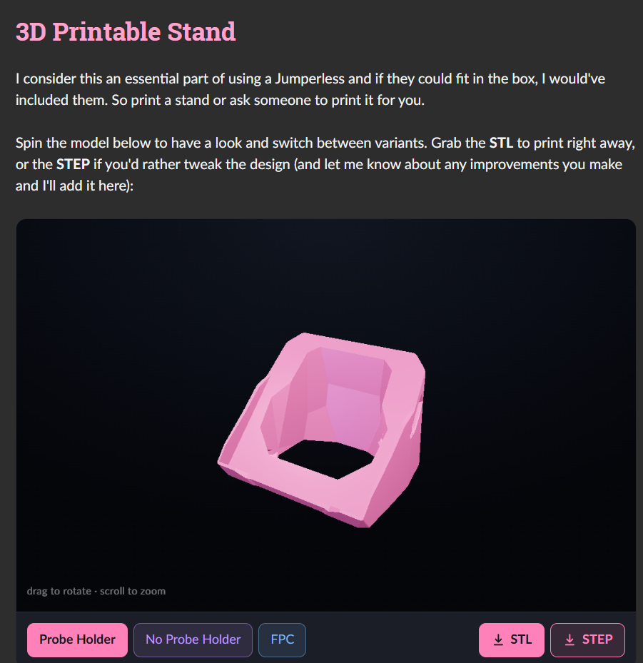
Its GitHub repository provides hardware designs, firmware, PCB resources, mechanical models, and application software, allowing developers to inspect or modify the complete platform.
Because the routing, measurement, and control systems are programmable, developers can also build their own applications on top of the platform rather than using it only as a conventional breadboard.
Conclusion
Jumperless V5 demonstrates a different approach to hardware prototyping by replacing fixed jumper wiring with software-defined electrical connections.
The combination of an RP2350B, analog crosspoint switching, programmable power supplies, measurement functions, RGB visualization, MicroPython, and Wokwi integration transforms a traditional breadboard into a programmable hardware development environment.
While WIZnet Ethernet is not currently part of the original design, the project's programmable I/O and routing architecture also presents an interesting opportunity for adding wired Ethernet connectivity.
This could extend the concept from:
Software-Defined Breadboard
to:
Network-Connected Software-Defined Hardware Lab
