Why Does a W5500 Ethernet Link Carry ROS 2 Drive Commands in the ULSTU Buggy?
ULSTU put a W5500 on the ESP32 board of its Ackermann teaching robot, so a Jetson AGX Xavier sends JSON-RPC drive commands and reads IMU data over wired UDP.

WIZnet - W5500
x 1

Ethernet controller on the ULSTU low-level control board. Carries ROS 2 drive commands from a Jetson AGX Xavier to the ESP32 as JSON-RPC over UDP port 9090, and returns IMU samples on the same port. T
📌 An Ackermann Teaching Robot From Ulyanovsk State Technical University
Ulyanovsk State Technical University created the buggy-learn repository on GitHub on 2025-04-05, and the low-level control board of the robot inside it carries a WIZnet W5500 Ethernet controller. The GitHub organisation ulstu lists its location as Ulyanovsk, Russia and its contact address as fist@ulstu.ru. The repository is MIT licensed, copyright 2025 Ulyanovsk State Technical University, with commits from k.svyatov@ulstu.ru and the account ghub-ayrtom, the last of them on 2025-04-11.
ULSTU describes buggy-learn as a platform for learning robotics from scratch, shipping 3D models, control libraries, a virtual proving ground, a map editor and circuit designs alongside the physical robot. The published progression diagram runs from block programming for school grades 4 to 9, through a ROS 2 simulator for grades 10 to 11, to ROS 2 on the real robot for engineering teams.
Why Ackermann Steering Changes the Software Stack
Most teaching robots, and most ready-made ROS packages, assume differential-drive or mecanum wheels that can spin in place. Real cars steer with Ackermann geometry, where the front wheels turn through slightly different angles and the vehicle cannot rotate about its own centre, which restricts the trajectories a planner may produce. ULSTU chose an Ackermann chassis so that lab work transfers to full-size driverless cars.
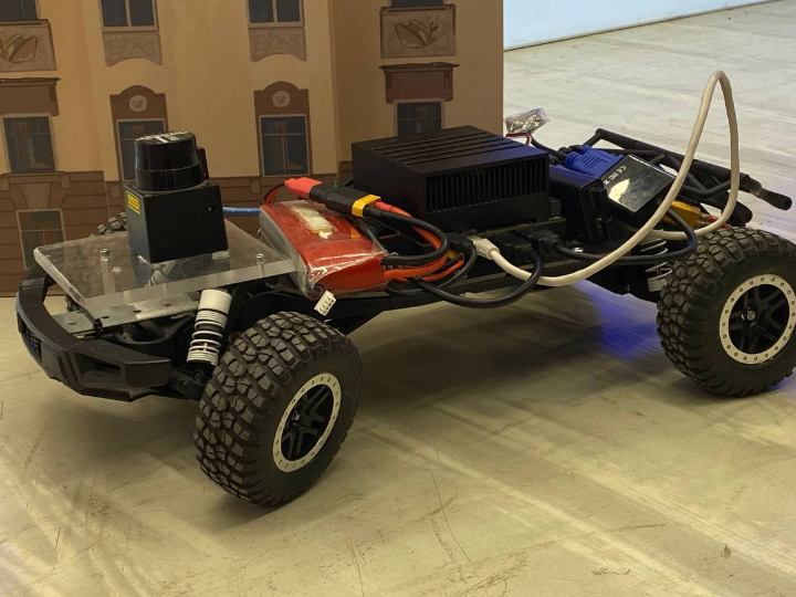
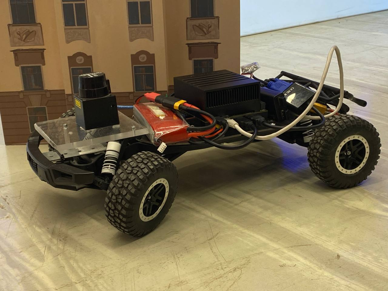
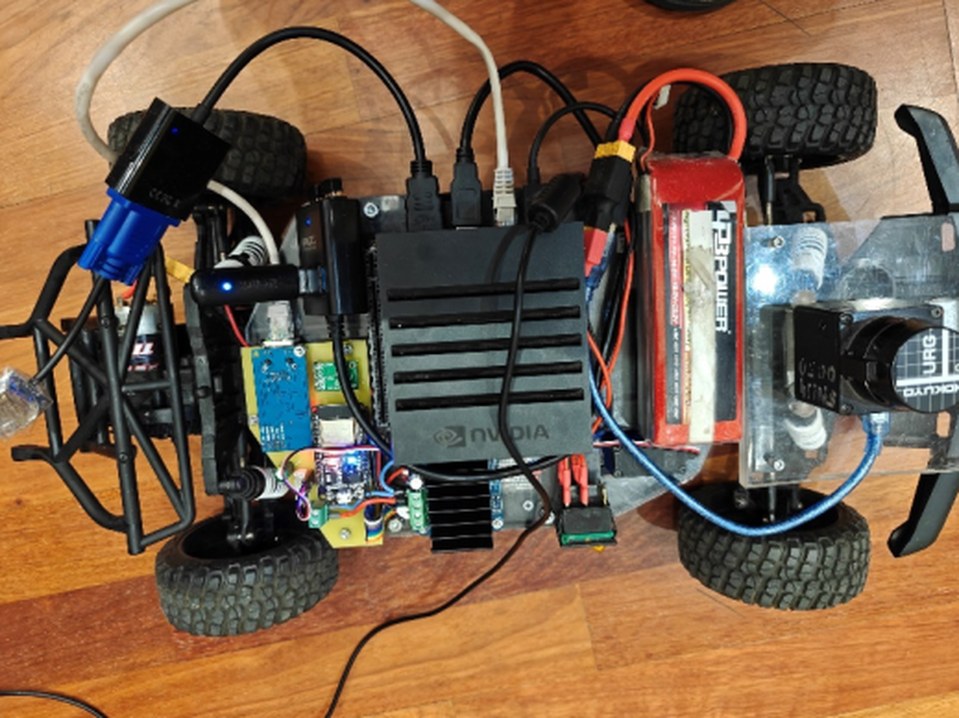
The base is a Traxxas Raptor Ford F-150 short-course radio-controlled model with the factory radio gear removed and replaced by a networked control kit, a Nvidia Jetson AGX Xavier and a Hokuyo laser rangefinder. That choice shows up in the code as ackermann_keyboard_teleop_node.py, a WASD keyboard node publishing ackermann_msgs/AckermannDrive on /cmd_ackermann with ROBOT_MAX_SPEED set to 8.0 cm/s and ROBOT_MAX_STEERING_ANGLE set to 30.0 degrees.
The Two Layers and the Board That Joins Them
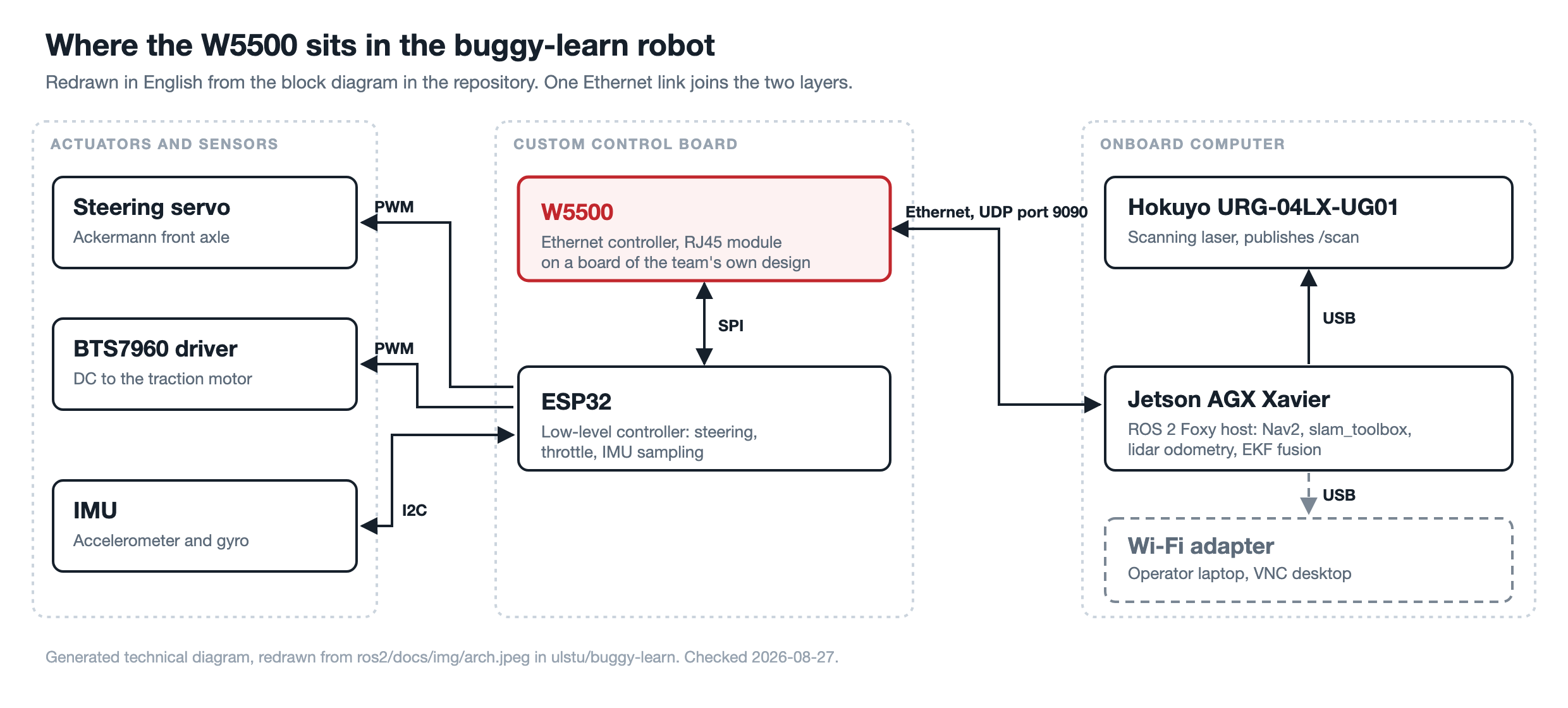
The upper layer of the ULSTU buggy is a Nvidia Jetson AGX Xavier running Ubuntu 20.04 and ROS 2 Foxy. The README explains that choice by the age of the hardware, noting the Xavier was released in 2018, and states the same instructions were tested on Ubuntu 22.04 with ROS 2 Humble. A Raspberry Pi or the cheaper Orange Pi can take the same role.
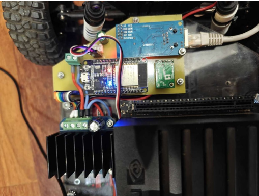
The lower layer is a board of the team's own design. The README lists an ESP32-family microcontroller, a W5500 Ethernet module, a MEMS inertial measurement unit, a 12 V to 5 V converter, and connectors for a BTS7960 transistor board and the steering servo. The perception sensor is a Hokuyo URG-04LX-UG01 single-plane lidar, which the README says can be swapped for equivalent Chinese units, with a camera as an optional addition.
Autonomy here means physical self-containment as well as software. The README states it plainly: "Все оборудование размещается непосредственно на роботе, что позволяет работать полностью автономно", meaning all the equipment sits directly on the robot so it can operate fully autonomously.
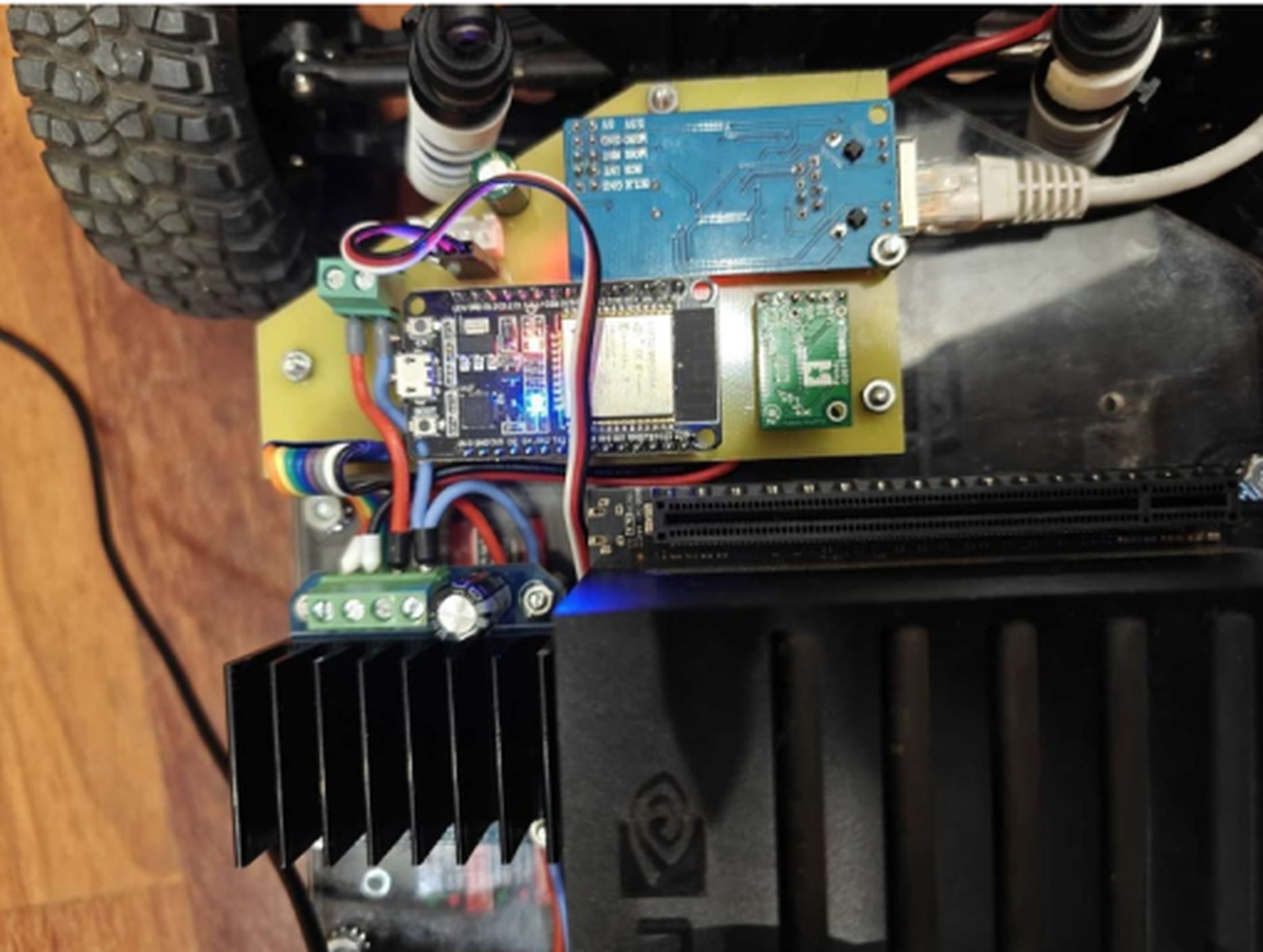
⚙️ What the W5500 Does for This Robot
The README states the networking decision in one sentence: "В отличие от многих других роботов для обмена данными используется интерфейс Ethernet, реализованный при помощи W5500." In English, unlike many other robots, data exchange uses an Ethernet interface implemented with a W5500.
The README then lists three benefits of that Ethernet link: high operational stability, immunity to interference, and no need to occupy the microcomputer's Wi-Fi adapter or to have an external wireless network available. The root README adds the performance claim, that the ESP32 with its Ethernet module transmits control commands and odometry data "надежно и с низкими задержками", reliably and with low latency.
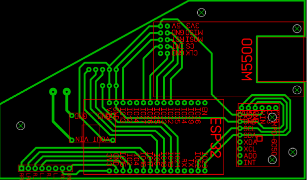
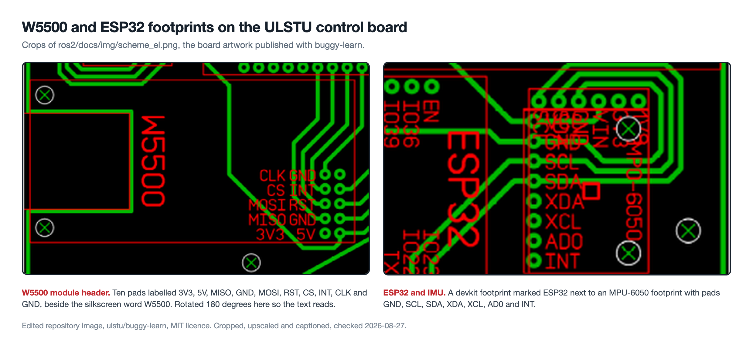
The published board artwork backs the README. A silkscreen block marked W5500 sits next to a ten-pad module header labelled 3V3, 5V, MISO, GND, MOSI, RST, CS, INT, CLK and GND, which is the standard SPI plus reset and interrupt pinout of an off-the-shelf W5500 module. The same artwork shows an ESP32 devkit footprint and, next to it, an MPU-6050 footprint whose pads read GND, SCL, SDA, XDA, XCL, AD0 and INT.
How Drive Commands and IMU Data Share One Cable
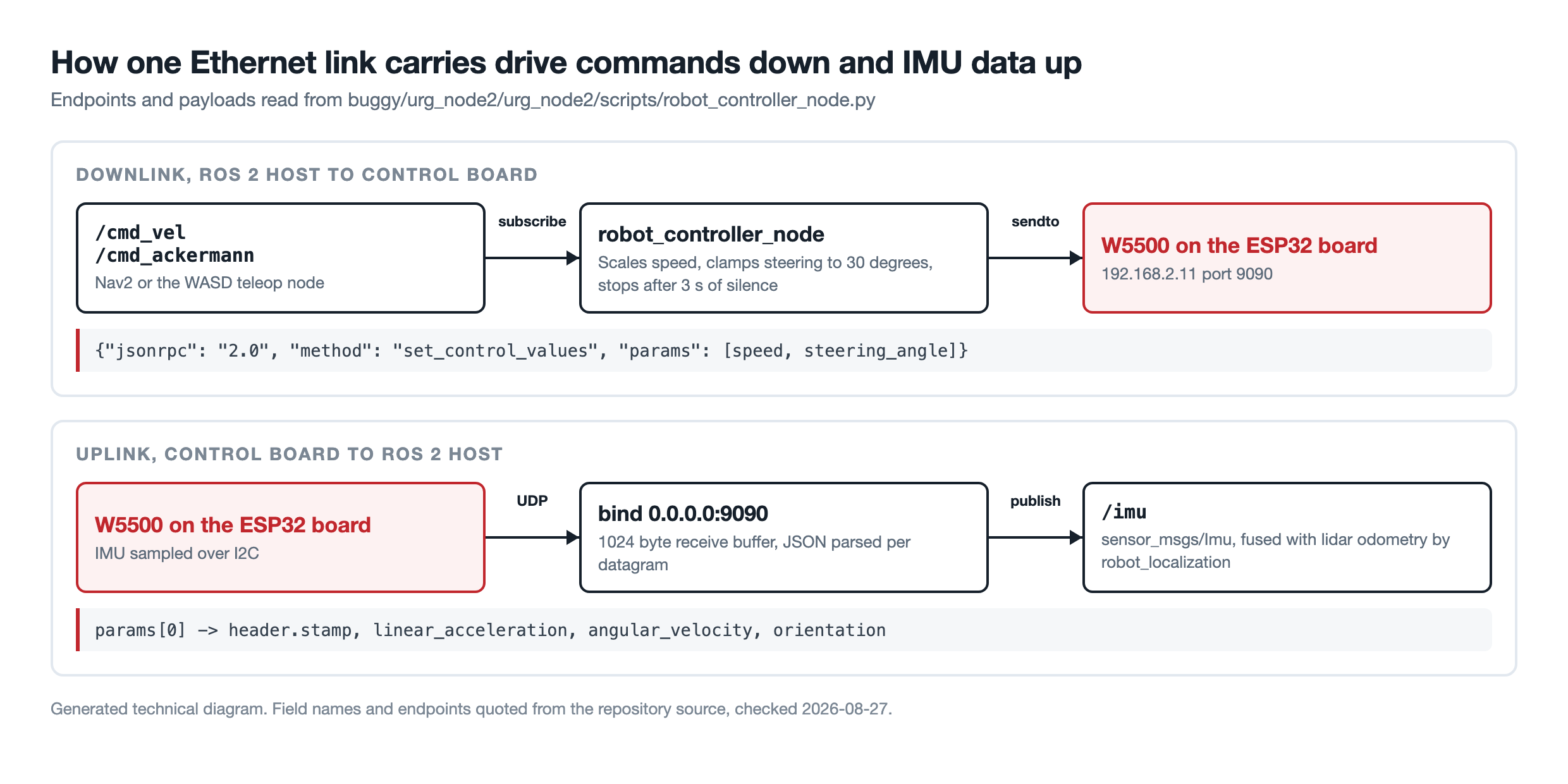
The bridge between the two layers is a single Python node, buggy/urg_node2/urg_node2/scripts/robot_controller_node.py. It defines UDP_SERVER_IP = '192.168.2.11', UDP_SERVER_PORT = 9090 and RECV_BUFFER_SIZE = 1024, then subscribes to /cmd_vel and /cmd_ackermann and sends each command down as a JSON-RPC 2.0 datagram.
jsonrpc_message = {
    'jsonrpc': '2.0',
    'method': 'set_control_values',
    'params': [speed, steering_angle],
}

jsonrpc_message_str = json.dumps(jsonrpc_message)
self.__sock.sendto(jsonrpc_message_str.encode(), (UDP_SERVER_IP, UDP_SERVER_PORT))
Conversion from ROS 2 velocity commands happens in the same node. Nav2 publishes geometry_msgs/Twist on /cmd_vel, and the node multiplies linear.x by 17.5, multiplies angular.z by -500, then clamps the steering angle to plus or minus 30 degrees before sending. A watchdog in the receive thread stops the robot if no /cmd_vel message has arrived for more than three seconds, which matters on a vehicle whose throttle is held by a separate microcontroller.
The return path uses the same port in the opposite direction. A background thread binds 0.0.0.0 on port 9090, reads datagrams of up to 1024 bytes, parses each as JSON, and copies params[0] into a sensor_msgs/Imu message: the timestamp in seconds and nanoseconds, linear acceleration, angular velocity and orientation. That message is published on /imu, which is where the robot_localization package picks it up.
| Link | Interface | Endpoint or setting | Where it is stated |
|---|---|---|---|
| ESP32 to W5500 | SPI | Ten-pad header: 3V3, 5V, MISO, GND, MOSI, RST, CS, INT, CLK, GND | Board artwork ros2/docs/img/scheme_el.png |
| Control board to onboard computer | Ethernet, UDP | 192.168.2.11 port 9090, 1024 byte receive buffer | robot_controller_node.py |
| ESP32 to IMU | I2C | MPU-6050 footprint, SCL and SDA pads | Board artwork and block diagram |
| Onboard computer to lidar | USB or Ethernet | ip_port 10940, ip_address left blank in the shipped file | config/params_ether.yaml |
| Onboard computer to operator laptop | USB Wi-Fi adapter | Remote desktop session | Block diagram and repository photographs |
Mapping and Navigation on the Onboard Computer
One launch file, urg_node2.launch.py, starts the whole robot, and the README shows which entries to comment in or out for mapping, for localisation and for EKF fusion. The composed node list is the part a reader would otherwise have to assemble by hand:
urg_node2_node, the Hokuyo lifecycle driver publishing/scanlidar_odometry_node, scan matching that publishes/odomand the odom transformrobot_state_publisher, fed byrobot.urdf.xacrorobot_controller_node, the UDP bridge to the ESP32 boardekf_filter_nodefromrobot_localization, fusing lidar odometry with the IMUasync_slam_toolbox_nodefor mapping, orlocalization_slam_toolbox_nodefor pose trackingrvizplusjoint_state_publisher_guifor visualisation and wheel joints- a static transform publisher tying
maptoodom
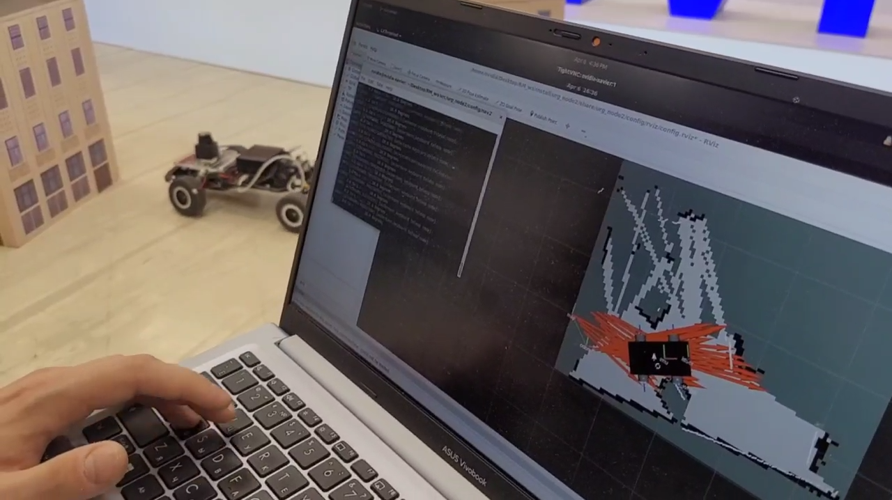
The lidar odometry node declares three tunable parameters, defaulting to 0.25 m for max_correspondence_distance, 0.005 for transformation_epsilon and 30 for maximum_iterations, and the README says they can be retuned for odometry quality or for lower compute cost. Mapping runs slam_toolbox in mapping mode, after which the operator saves and serialises the map from an RViz panel.
The repository ships five saved maps. The one nav2_params.yaml points at, real_map.pgm, is 97 by 83 pixels at 0.05 m per pixel, so that space is roughly 4.85 m by 4.15 m, an indoor room rather than a car park. Localisation can then use slam_toolbox in localization mode or AMCL from Nav2, whose parameter block in the README sets laser_max_range to 5.6 m, particles between 100 and 500, and 30 beams per update, all commented out in the shipped file.
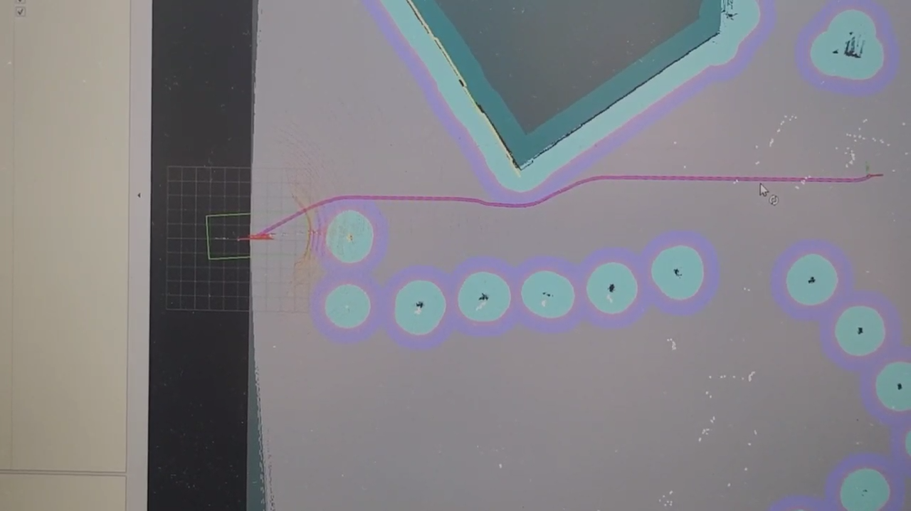
What Still Runs Over the Air
The wired link is not a claim that the robot is wireless-free. The block diagram in the repository shows a Wi-Fi adapter attached to the Jetson AGX Xavier over USB, and repository photographs show an operator laptop driving RViz through a remote desktop session to a host named nvidia-xavier. The split is the useful part: the real-time control loop and the IMU stream stay on the cable between the ESP32 board and the onboard computer, while the operator connection stays wireless.
What the Repository Publishes and What It Does Not
The firmware for the ESP32 board is not in this repository. A listing of the 881 tracked files outside node_modules, checked on 2026-08-27, contains no ESP-IDF or Arduino project for the control board, so the register-level detail of how the W5500 is driven cannot be read here. What the repository does publish is the ROS 2 side, the board artwork and the wire protocol, which is enough to rebuild the link against any firmware.
A related repository from the same organisation shows the house pattern. ulstu/cad-self-driving, created on 2022-05-31 and last pushed on 2025-07-24, holds ESP32 control units for full-size vehicles whose sdkconfig files carry CONFIG_ETH_SPI_ETHERNET_W5500=y and whose Ethernet.cpp opens the SPI device at 36 MHz. That is a different vehicle programme, but it is the closest published reference for the low-level side.
Two smaller gaps are worth naming. The README describes the inertial sensor as a MEMS device from ST Microelectronics while the board artwork carries a GY-521 MPU-6050 footprint, so a rebuilder should trust the artwork. The board is published as a rendered image rather than schematic or Gerber sources, and no bill of materials or cost figure appears in the repository.
Related WIZnet Maker Projects
How to Bridge a ROS2 Jazzy Rover to Wired Ethernet with W5500 on ESP32? covers the same division of labour, an ESP32 handling motors and sensors below a ROS 2 host. The difference is the wire protocol, since SzufladaV2 carries its traffic over MQTT while the ULSTU buggy sends raw JSON-RPC datagrams and adds Ackermann steering limits.
How Did RoboMagellan Implement a UDP-Based Robot Motor Controller Using the RP2040 and W5500? is the closest match on the protocol side, a UDP command channel to a motor controller over a W5500. The difference is the microcontroller and the return path, since the ULSTU node reuses the same port to lift IMU samples into a ROS 2 topic.
PipeInspect: Wired Ethernet Control & Wi-Fi Video Streaming shows the same layering in a different machine, wired control with wireless payload traffic. The difference is what rides the wireless side, since PipeInspect streams camera video while the ULSTU buggy uses Wi-Fi only to reach the operator desktop.
❓ FAQ
Q. What does the ULSTU buggy use the W5500 for? The W5500 gives the ESP32 control board its Ethernet port, over which the Jetson AGX Xavier sends drive commands as JSON-RPC datagrams to 192.168.2.11 port 9090 and receives IMU samples on the same port.
Q. Why did ULSTU choose Ethernet for the control link? The README names three reasons: high operational stability, immunity to interference, and no need to occupy the onboard computer's Wi-Fi adapter or to provide an external wireless network. Wi-Fi is still used for the operator desktop.
Q. Is the ESP32 firmware published? No. A listing of the 881 tracked files on 2026-08-27 found no firmware project for the control board, so the SPI driver and pin assignment for the W5500 are not visible here.
Q. What ROS 2 version does the stack need? The instructions were written for ROS 2 Foxy on Ubuntu 20.04 because the Jetson AGX Xavier dates from 2018, and the README states the same steps were tested on Ubuntu 22.04 with ROS 2 Humble.
Q. Can this platform be rebuilt on cheaper hardware? The README names Raspberry Pi and Orange Pi as alternatives to the Jetson AGX Xavier, and says the Hokuyo URG-04LX-UG01 lidar can be replaced by equivalent units.
-
buggy-learn repository
The platform repository from Ulyanovsk State Technical University. MIT licence, created 2025-04-05, last push 2025-04-11.

-
Robot build and run instructions
Hardware description and the sentence stating that data exchange uses Ethernet implemented with a W5500, plus the ROS 2 build, mapping and navigation steps.
-
robot_controller_node.py
The UDP bridge. Defines 192.168.2.11 port 9090, the JSON-RPC set_control_values message, the 30 degree steering clamp and the three second watchdog.
-
Control board artwork
Board layout showing the W5500 silkscreen and its ten-pad SPI header next to the ESP32 and MPU-6050 footprints.
-
Control board mounted on the robot
Photograph of the installed board with a patch cable plugged into the blue W5500 Ethernet module.
-
Nav2 parameter file
Nav2 settings for the built map. The AMCL block ships commented out, and the README prints the same block with laser_max_range 5.6 m, 100 to 500 particles and 30 beams.
-
ULSTU on GitHub
Organisation profile of Ulyanovsk State Technical University, listing Ulyanovsk, Russia and fist@ulstu.ru.
-
WIZnet W5500
Datasheet and documentation for the Ethernet controller used on the control board.