
How to Design a Super Simple Sensor System for Industrial Monitoring Applications
This article describes an Ethernet-connected subsystem of a larger modular sensor system.

WIZnet - W5500
x 1

texasinstruments - MSP430 Microcontroller
x 1
This article describes an Ethernet-connected subsystem of a larger modular sensor system designed for industrial or smart home sensing and monitoring. We will discuss a custom sensor subsystem developed for this application.
Creating custom sensor solutions for home or automation typically requires a great deal of customization. A variety of sensors from perhaps several manufacturers are collected on a circuit board, firmware must be engineered, and a user interface or dashboard created. It isn’t overwhelmingly difficult work—but it can be rather tedious and time-consuming. The customization aspect may also make it cost-prohibitive in many use cases.
The idea behind this project was to create a “Super Simple Sensor System” that allows a wide variety of input and output nodes to be linked together with a common protocol with the fewest number of wires possible and low upgrade/replacement cost. This subsystem will hopefully spark creativity in your designs but it is not a market-ready product.
The inspiration came from the wonderfully designed Makeblock Neuron line of children’s educational toys. Multiple sensors and inputs (temperature, humidity, joystick, buttons, etc.) are connected with a variety of outputs and interfaces (LED display, buzzer, etc.) and all of the devices connect via magnetic spring-loaded pogo-pin connectors.
Ethernet Connectivity
Almost all devices that are hard-wired to the Internet have an 8P8C RJ45 jack. Either built into the jack or very close to the jack there is a pulse transformer. The pulse transformer galvanically isolates the integrated circuit from the cable. The isolation provides protection from DC fault conditions and eliminates problems associated with differences in the ground potentials of the transmitter and receiver. The transformer also functions as a differential receiver that suppresses common-mode noise, such as electromagnetic interference that is generated from high-power equipment and coupled equally into two tightly twisted signal wires.
The two options for circuit integration are an RJ45 jack with an external pulse transformer, or an RJ45 jack with integrated pulse transformer. The integrated option is often called a “MagJack” and is generally easier to use, but a tad more expensive. You only need to access two of the four pairs of wires for 10/100 communication. The other two pairs are not used at all! When I was selecting parts for this project, this thought didn’t occur to me, and I rejected several proposed MagJacks because they only provided access to two pairs of wires and had six-pin footprints—I needed an 8P8C jack, with two LEDs (each LED has separate anode and cathode pins), so I was searching for twelve-pin footprints or greater. Woops! Only four of the eight conductors are used. The moral of the story is this: If you’re not going to use all eight conductors, don’t pay for magnetics for the other two pairs of wires—the RJ45 jack will be the same size and perhaps a bit cheaper.
As you can see below, R7-R10 are damping resistors. I estimated their values based on other reference designs. They are necessary to prevent overshoot and ringing in the circuit. Testing would have to reveal if the lines are over/under/critically damped and the values adjusted accordingly. The transmit pair are pulled up to DVDD through 49.9Ω resistors, and the center tap is connected to DVDD through a 10Ω resistor and decoupled with a 22nF capacitor to ground. The receive pair passes through the damping resistors where it encounters two capacitors. The pair are tied through two 49.9Ω resistors to a 0.01 µF decoupling capacitor per manufacturer recommendation—they are further pulled up to DVDD through the center tap of the transformer winding.
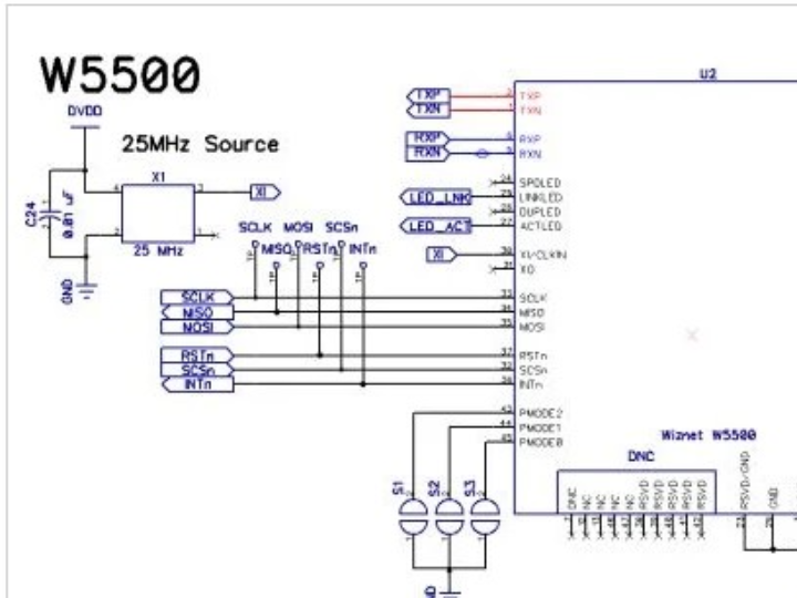
Wiznet W5500
From a hardware perspective, the WizNet W5500 is a pretty straightforward addition to the circuit. An external crystal oscillator must be included and a half-dozen or so analog decoupling capacitors are needed—one for every AVDD pin. Pins 43-45 are used to select the network mode. I included pads for solder bridges should it be necessary to use something other than the default configuration (as it turned out I didn’t need to change the mode).
The crystal oscillator manufacturer recommended the removal of copper from directly underneath the crystal. And I used ground pours to attempt to isolate the crystal’s output from the W5500 SCLK input line, although it was likely not necessary.