


How Does a W5500 Modbus TCP BMS Connect a Rescue Robot Battery to ROS 2?
A Paderborn University lab BMS runs a Modbus TCP server on a W5500 hardware socket, port 502, so a ROS 2 node reads cell data and publishes BatteryState.

WIZnet - W5500
x 1

Socketed W5500 Ethernet module on the STM32F446 controller board. Runs the Modbus TCP server on hardware socket 1, port 502, via the vendored ioLibrary_BSD driver over SPI1.
A Two-Board BMS Built for a Rescue Robot
Frank publishes on GitHub as frankonerio and signs the README of this project with a Paderborn University address, fokonkwo@mail.upb.de. His repository, described as "Smart Battery Management for Mobile Robots", contains a complete battery management system for GETjag, the tracked rescue robot of the university's GET Lab, and both custom boards carry the GET Lab logo on their silkscreen. GET Lab robots of this line have competed in the RoboCup Rescue league, where machines search simulated disaster sites for victims.
The project answers a practical robotics question: how a battery pack inside a robot reports per-cell voltages and state of charge to the ROS 2 software that runs the machine. Frank's answer is wired. An STM32F446 controller board runs a Modbus TCP server on a WIZnet W5500 hardware socket at port 502, and a ROS 2 node on the host computer reads the holding registers and republishes them as a standard sensor_msgs/BatteryState topic. The repository was created on 2024-06-03, the README is dated 15.01.2025, the last commit landed on 2025-03-30, and we verified the sources on 2026-08-28.
Two Custom KiCad Boards: BQ76952 AFE and STM32F446 Controller
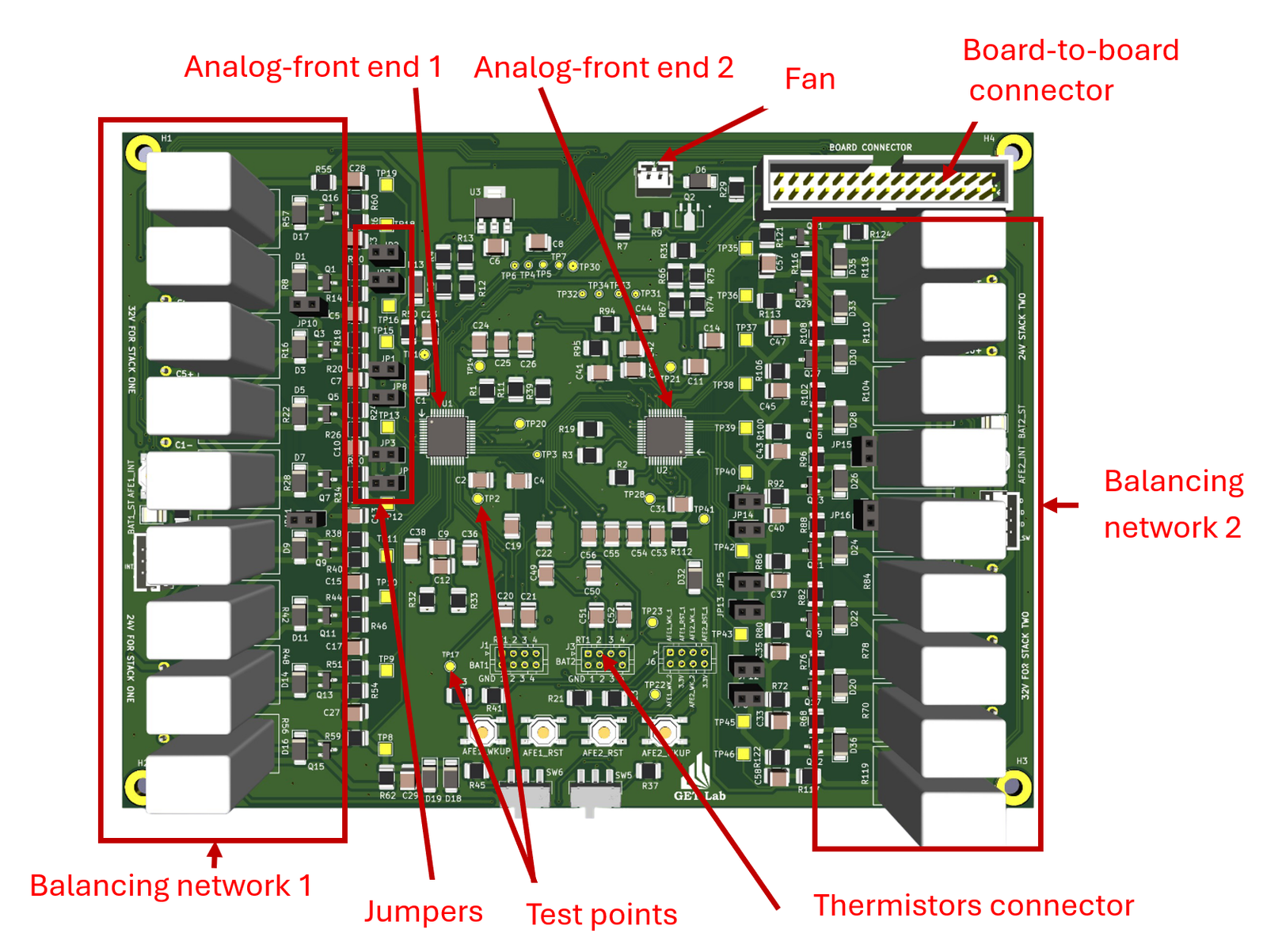
The hardware is a two-board stack designed in KiCad, and the schematics, PCB layouts, and annotated renders are published in the repository's KiCAD folder. The analog front end board carries two Texas Instruments BQ76952 battery monitor ICs, one per battery stack, plus balancing networks for both stacks, thermistor connectors, a fan header, and rows of jumpers and test points. The schematic file name, Double_Pack_BMS_BQ76952, states both the part and the dual-pack intent, and the firmware file bq_common.c drives the chip's I2C subcommand protocol with CRC support.
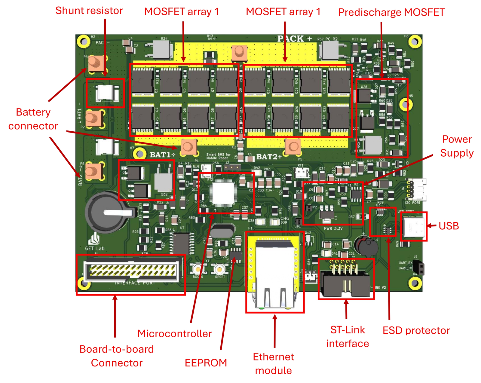
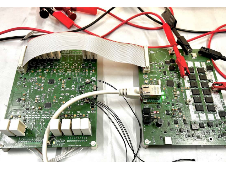
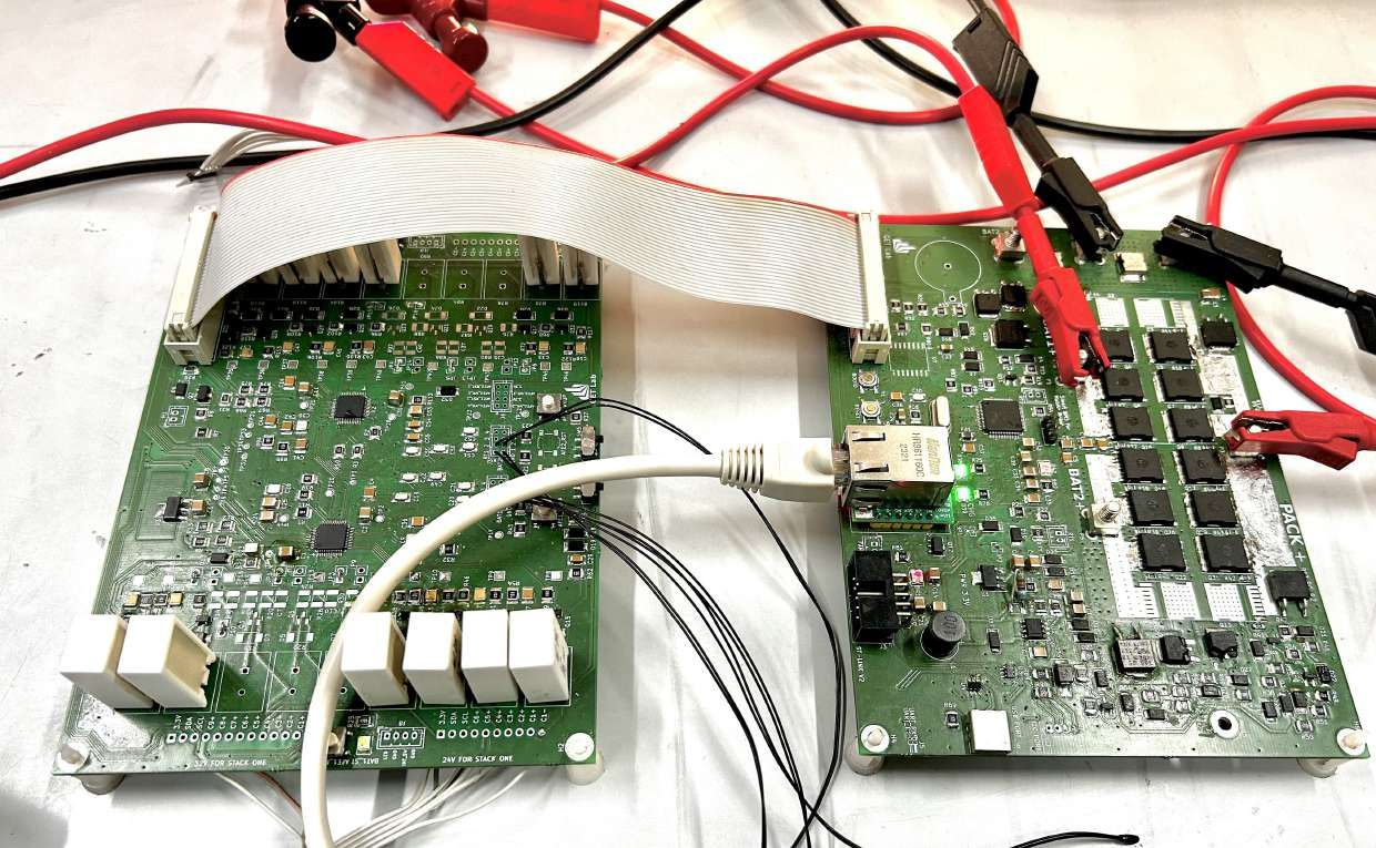
The controller board is the one with the network on it. Its annotated render calls out the microcontroller, an STM32F446RET6 per the CubeIDE project file, along with an EEPROM, two MOSFET arrays with a predischarge MOSFET for pack switching, a shunt resistor, an ST-Link programming header, a USB port, and an "Ethernet module" socket. The W5500 is not soldered down as a bare chip here: an off-the-shelf W5500 Ethernet module plugs into that socket, and the bench photo shows the module seated with a live link light.
From Battery Cells to a ROS 2 Topic
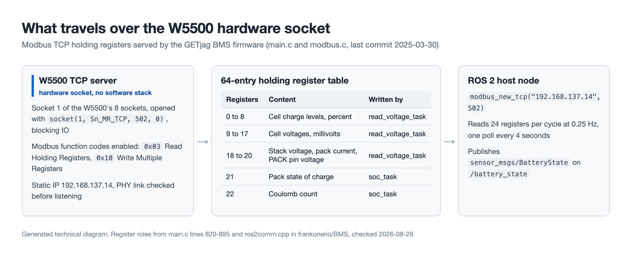
Cell data starts at the BQ76952 front ends, which measure the cells and run balancing. The STM32F446 polls them over I2C, computes pack state of charge, and copies results into a 64-entry Modbus holding register table. Cell charge levels in percent occupy registers 0 to 8, raw cell voltages in millivolts occupy registers 9 to 17, and stack voltage, pack current, and PACK pin voltage fill registers 18 to 20. The pack state of charge sits in register 21 and the running Coulomb count in register 22, all written in main.c between lines 820 and 895.
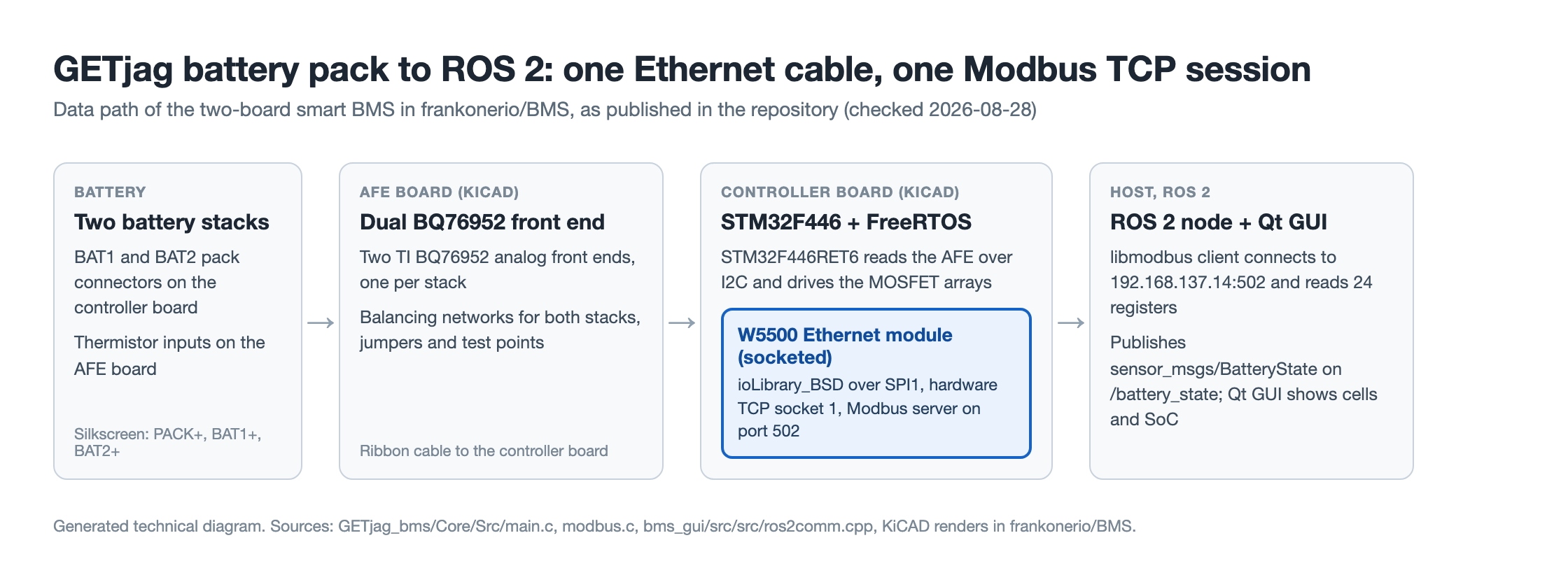
On the host side, the bms_gui package is a ROS 2 node built with colcon. Its ros2comm.cpp opens a libmodbus client with modbus_new_tcp("192.168.137.14", 502), reads 24 holding registers per cycle at a 0.25 Hz WallRate, one poll every 4 seconds, and publishes sensor_msgs/BatteryState on the /battery_state topic. A Qt window displays the individual cell readings and the state of charge, and its layout can be edited in Qt Creator from the mainwindow.ui file in the qt_gui folder.
The W5500 Hardware Socket as the Modbus TCP Server
The README lists the network layer by name: "Wiznet W5500 ioLibrary_BSD" appears in the component list next to ROS 2, libmodbus, FreeRTOS, STM32CubeIDE, and SEGGER SystemView, and section 5, titled "Integrating W5500 Ethernet Library", instructs the builder to set #define _WIZCHIP_ W5500. The library is not merely referenced. The driver sources socket.c, wizchip_conf.c, and w5500.c are vendored into the firmware tree at GETjag_bms/Core/Src/w5500 and compiled into the build.
The initialization in main.c registers chip-select and SPI callbacks with reg_wizchip_cs_cbfunc and reg_wizchip_spi_cbfunc on SPI1, calls ctlwizchip with 2 KB buffers for each of the eight sockets, assigns the static address 192.168.137.14 through ctlnetwork, and waits for PHY link-up before serving. The Modbus task then opens hardware socket 1 as a TCP server:
// GETjag_bms/Core/Src/main.c
if (socket(1, Sn_MR_TCP, LISTEN_PORT, 0) != 1) { ... }   // LISTEN_PORT is 502
uint8_t socket_io_mode = SOCK_IO_BLOCK;
ctlsocket(1, CS_SET_IOMODE, &socket_io_mode);
listen(1);
The server loop then watches the socket status register until it reads 0x17, the established state, and drops back to listening whenever the client disconnects. Even the MAC address is on brand: the firmware assigns 00:08:dc:ab:cd:ef, and 00:08:DC is WIZnet's own OUI block.
TCP and IP run inside the W5500 silicon, so the firmware carries no lwIP or other software stack. The modbus.c parser handles the two enabled function codes, 0x03 Read Holding Registers and 0x10 Write Multiple Registers, and answers straight into the hardware socket with send(1, ...). The Cortex-M4 spends its cycles on cell measurement, protection, and estimation while the Ethernet controller keeps the TCP session alive.
FreeRTOS Tasks, SoC Estimation, and the State Machine
The firmware splits its work across four FreeRTOS tasks created in main.c, synchronized with a data-ready semaphore so the Modbus reply ships a consistent snapshot.
| Task | Priority | Role |
|---|---|---|
| modbus_comm_task | 2 | Waits for PHY link, runs the TCP server on W5500 socket 1, calls the Modbus parser |
| read_voltage_task | 2 | Reads cell and pack measurements from the BQ76952 and fills registers 0 to 20 |
| soc_task | 3 | Runs Coulomb counting and writes state of charge and the Coulomb count to registers 21 and 22 |
| bms_state_machine_task | 3 | Switches the pack between OFF, CHG, DIS, NORMAL, and SHUTDOWN states |
The README describes the estimation module as "Coulomb counting and extended Kalman filter functions", while the published soc_soh.c implements Coulomb counting seeded by a 16-entry open-circuit-voltage lookup table that maps the lowest cell voltage to releasable capacity. State of health and depth of discharge come out of the same counters. The state machine in bq_common.c gates charging and discharging through the MOSFET arrays according to the five pack states.
The firmware initializes the front end with a cell-select mask of 0x801F, which the source comments as six selected cells. The mask places the top cell on the chip's sixteenth measurement channel, so main.c fills register 8 from CellVoltage[15], and the Qt window carries nine cell readouts, one per holding register 0 to 8.
The project is also instrumented for real-time debugging. SEGGER SystemView target sources are integrated per the README's section 4, so task execution on the STM32F446 can be traced cycle by cycle, and the Records folder holds four captured .SVdat trace files from real sessions.
What the Repository Shows and What It Leaves Open
The repository holds full KiCad sources for both boards, complete firmware, and the host-side ROS 2 package, which makes the design reproducible end to end. The bench photo is the single real photograph, and it carries real evidence: flux residue, test leads, the ribbon cable, and the lit Ethernet link LED. There is no license file, no release, and no photo of the BMS mounted inside GETjag itself, so deployment on the robot is supported by the project naming and the GET Lab branding rather than by a field image. Development activity ended with the 2025-03-30 commit, and the repository shows 0 stars as of 2026-08-28, which says more about visibility than about the engineering.
Related WIZnet Maker Projects
How to Build a Maker Modbus TCP Server with WIZnet W5500 on STM32F4? documents the same core stack, an STM32F4 serving Modbus TCP from a W5500 hardware socket. That post is a firmware reference, while Frank's project wraps the identical server pattern inside a finished battery product with its own AFE hardware.
How Does YamBMS Merge Multiple ESS BMS Units for One Inverter Over W5500 Ethernet? shares the battery management domain over W5500 Ethernet. YamBMS aggregates commercial BMS units for stationary energy storage, whereas the Paderborn design is the BMS itself, built from the AFE up for a mobile robot.
W5500-Based ESP32-S3 micro-ROS Node Suite for a Distributed Rover Control System also feeds battery telemetry into ROS 2 over W5500 Ethernet. Its nodes speak micro-ROS natively on the microcontroller, while the GETjag BMS keeps the firmware a plain Modbus slave and does the ROS 2 conversion on the host.
Why Does a W5500 Ethernet Link Carry ROS 2 Drive Commands in the ULSTU Buggy? is another university robot that trusts a W5500 wire between the robot computer and an MCU. The buggy sends drive commands downstream over JSON-RPC, the opposite direction of the GETjag BMS, which streams battery data upstream over Modbus.
FAQ
Q. What does this project use the W5500 for? The W5500 is the entire network layer of the BMS. A socketed W5500 module on the STM32F446 controller board runs a Modbus TCP server on hardware socket 1, port 502, using the vendored ioLibrary_BSD driver, with no software TCP/IP stack in the firmware.
Q. Which chip measures the battery cells? Two Texas Instruments BQ76952 battery monitor ICs on the AFE board, one per stack. The STM32F446 reads them over I2C using the subcommand protocol implemented in bq_common.c.
Q. Why does the BMS speak Modbus TCP instead of a native ROS 2 transport? The repository does not state a reason, but the structure has a clear effect: the firmware stays a standard Modbus slave that any industrial client can poll, and the ROS 2 dependency lives entirely in the host node that converts registers into a BatteryState message.
Q. Can the firmware be rebuilt? Yes. The GETjag_bms folder is a complete STM32CubeIDE project with FreeRTOS as a submodule, and the README documents the compiler paths for FreeRTOS, SEGGER SystemView, and the W5500 ioLibrary, dated 15.01.2025.
Q. Is the hardware design open? The KiCAD folder contains schematics, PCB layouts, and netlists for both the controller board and the AFE board, though the repository includes no license file, so reuse terms are formally undefined.
-
BMS repository (frankonerio/BMS)
Full project: STM32CubeIDE firmware, KiCad boards, ROS 2 host node, Qt GUI

-
Project README
Build instructions including section 5, Integrating W5500 Ethernet Library
-
WIZnet ioLibrary_Driver
The W5500 socket driver family vendored into the firmware at Core/Src/w5500
-
WIZnet W5500 product page
Hardwired TCP/IP Ethernet controller serving the Modbus TCP session
-
libmodbus
Host-side Modbus TCP client library used by the ROS 2 node
-
Paderborn University news on its RoboCup rescue robots
University coverage of the GET Lab rescue robot line at RoboCup (German)
-
SEGGER SystemView
Task tracing tool integrated into the FreeRTOS firmware; captures are in the Records folder


