
Wiz IoT Cam using W5300 TOE and 8051 limited resource uC
To show W5300 capability as TCP Offload Engine to interface it with 8051 core based MG8218D16 simple uC and OV2640 Camera with MQTT
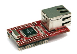
WIZnet - WIZ810MJ
x 1
W5300 TOE Module
Video Demonstration :
Project Description : Goal of this project is to show capability of W5300 TOE chip to interface it with low cost (0.2$) limited resources 8051 core based MG82F6D16 uC and develop IoT based camera to capture and transfer image via MQTT using onboard ARDUCAM 2MP camera to Wizcam android application running anywhere in world. (Without having luxury to use Arduino IDE and 3rd party libraries for W5300, Arducam OV2640 and MQTT :) )
Components used in project :
- W5300 Module WIZ830MJ 1 Pcs
- MG82F6D16 (8051 Core) Low cost 0.2$ Microcontroller 1 Pcs
- Arducam Mini 2MP SPI Camera 1 Pcs
- Buzzer 3V3 1 Pcs
- Misc (AM1117 3.3V LDO, Resistors, Capacitors, pushbutton, connectors, LEDs)
Software Used in Project :
- MG82F6D16 firmware build using Keil C51 and also supported SDCC open source 8051 compiler.
- MG82F6D16 SDK
- Megawin 8051 COM Port ISP to upload firmware via UART to MG82F6D16.
- Cool Term used as UART Debug Console
- Processing for Android used to develop Host Android Applications
Deliverables (everything required for replicate this project are under BSD3 opensource license and attached in documents section of this project):
- MG82F6D16 uC firmware for Project
- Android Application Source code and APK file
- Schematic and Hardware interfacing guide
Challenges and solution:
Challenges | Solution / Hacks |
Interface W5300 ToE module with MG82F6D16 8051 uC having only 24 GPIO | Implemented W5300 Indirect addressing with 8 Data lines to reduce pin usage. Only 14 pins required for w5300 interface (8 Data lines, A0, A1, A2, /CS, /RD, /WR) Yummy.. Still I have 10 pins left to manage Camera, Buzzer, UART Console and few LED interface with MG82F6D16 uC |
Arduino like IDE not available for MG82F6D16 8051uC | Developed firmware from scratch that is compatible Keil C51 and SDCC Opensource 8051 tool chain. |
Library not available for W5300 Initialization and TCP Socket Programming in indirect addressing mode. | Used datasheet of W5300 and developed low level IO Driver APIs and TCP Socket function from scratch for MG82F6D16 uC that can be also used with other uC with simple IO mapping and GPIO register mapping. |
MQTT 3.0 Client implementation without any available library for limited resource MG82F6D16 8051 uC having only 1KB RAM and 16KB flash. | Developed MQTT v3.0 Client APIs from scratch on top of TCP socket functions for MG82F6D16 8051 uC. |
Not enough pins available for OV2640 2MP Camera sensor interface with MG82F6D16 8051 uC. | Used ArduCam Mini 2MP SPI OV2640 Camera module in project that requires only 6 MG82F6D16 8051 uC GPIOs (2 for I2C and 4 for SPI) |
No Arducam Library available for MG82F6D16 8051 uC. | Developed firmware for ArduCam APIs from scratch to initialize OV2640 for 320x240 Color JPEG image capture via I2C and read Captured image bytes via SPI. |
Only 1 KB RAM of MG82F6D16 8051 uC is not enough to store JPEG image file. | Used smart way in firmware to give command to camera for capture JPEG image and at same time started putting MQTT Packet publish header bytes to TCP Socket and when image is ready, read one by one byte from ArduCam via SPI and send it to W5300 TCP socket TX FIFO until JPEG termination character received. Surprisingly this approach happily end up with only 96 bytes of RAM utilization for entire final project firmware. |
After assigning Pins to W5300 I realized that Hardware I2C Pins of MG82F6D16 8051 uC is mapped as normal GPIO for W5300 Data lines no Hardware I2C pins available for OV2640 interface. | Implemented bit banging for I2C implementation in MG82F6D16 8051 uC firmware as I2C only used for initialization of OV2640 on startup and not time critical in image transfer as image transfer is happily done with Hardware SPI running on 4 MHz SPI clock. |
Through put | Achieved 3-5 320x240 JPEG Image publishing per second on MQTT broker running on local network, and 1-2 images publish per second achieved on public MQTT Broker (HiveMQ)/ MQTT Broker hosted on Amazon AWS EC2. |
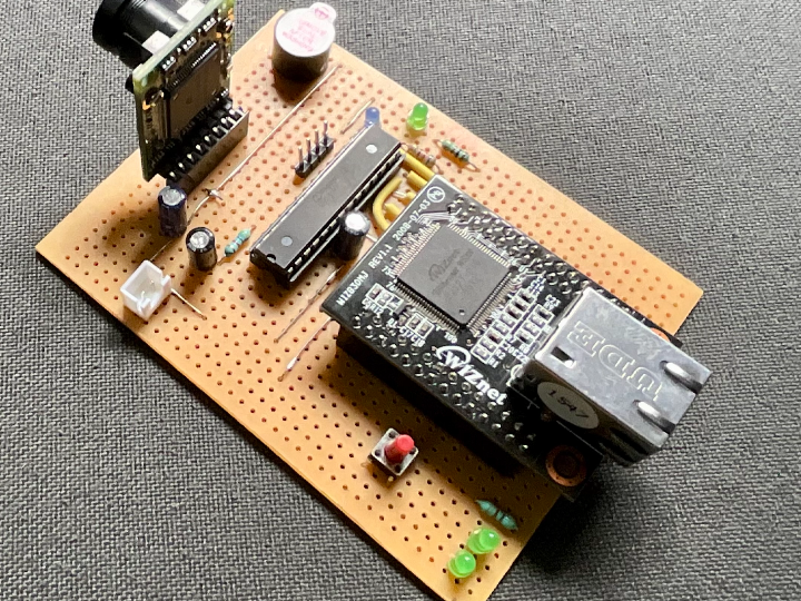
WizCam Assembled Hardware :
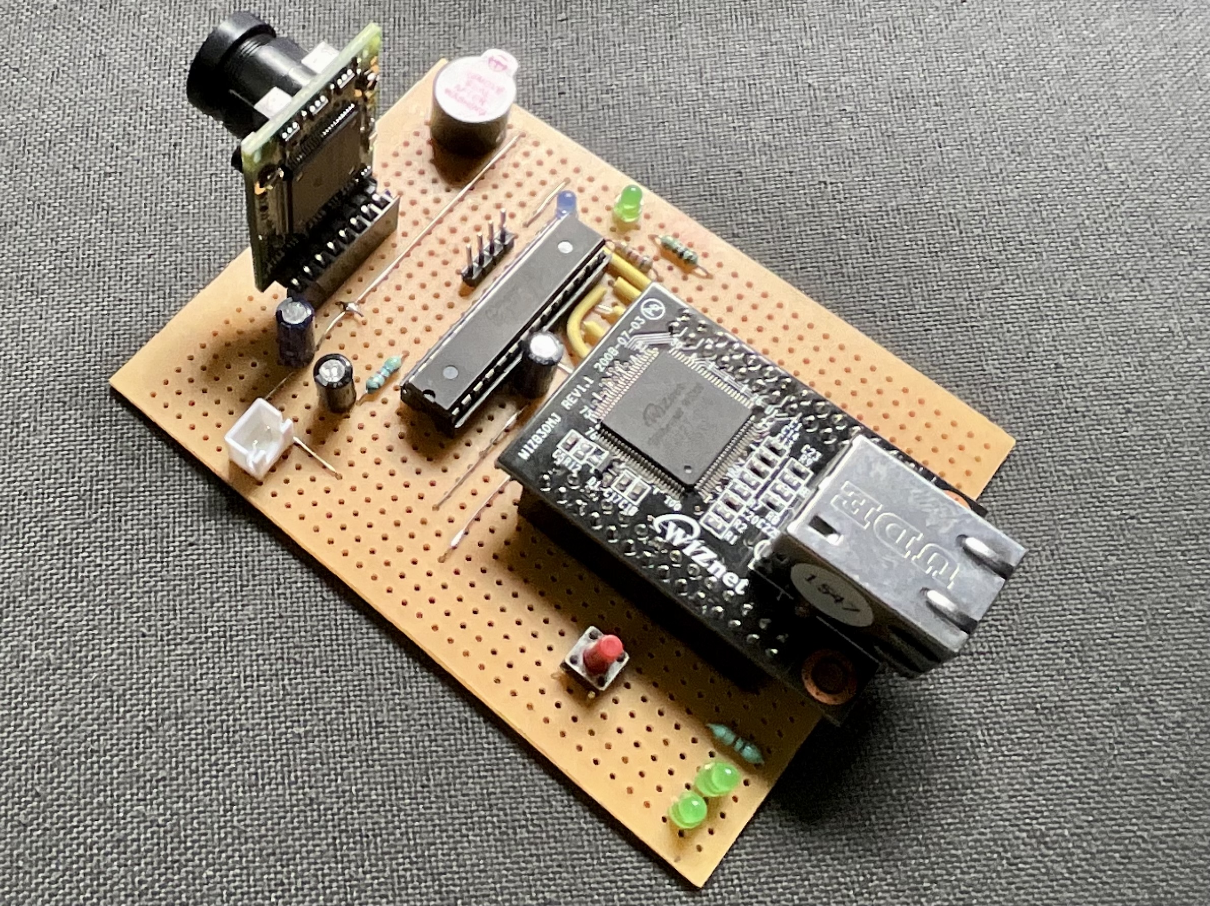
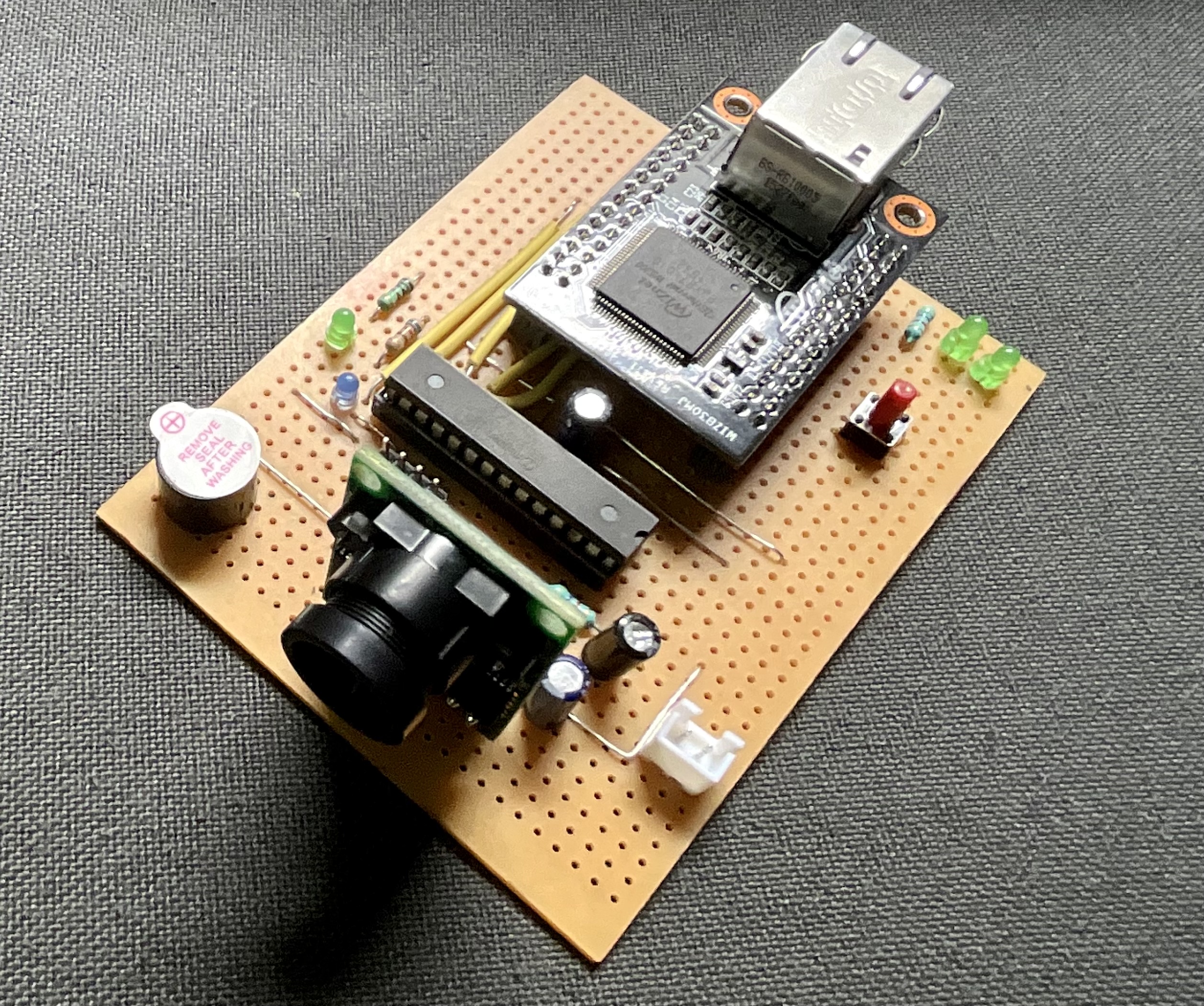
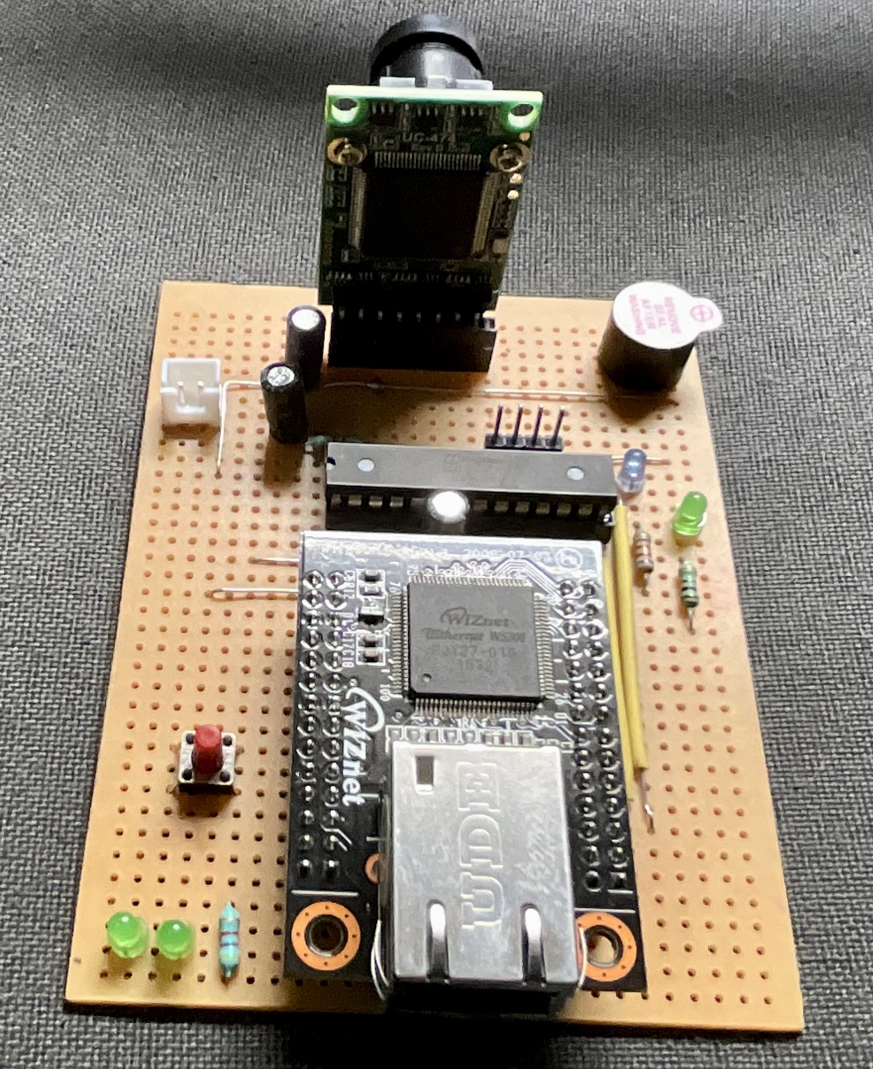
WizCam Hardware Details : Following image shows components used on Wiz IoT Cam board.
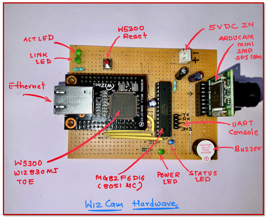
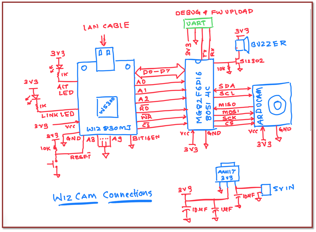
WizCam Hardware connection diagram : Following image shows connection diagram of Wiz IoT Cam board.
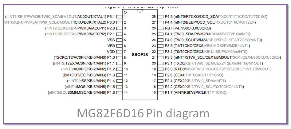
MG82F6D16 Micro controller Pin Diagram :
WizCam Hardware Pin Mapping : Following image shows pin mapping used on Wiz IoT Cam board.
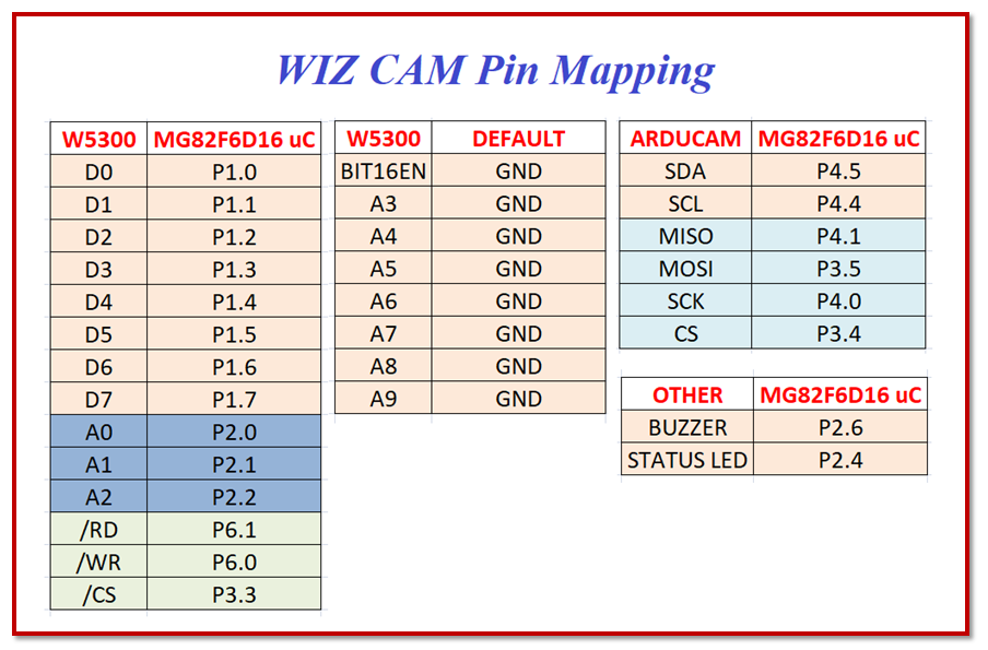
- W5300 Interfaced with MG82F6D16 using Indirect 8 bit addressing mode by 8 Data pins, 3 address pins (A0,A1,A2) and three control pins (/RD, /WR, /CS)
- Apart from W5300 to MG82F6D16 8Bit Indirect Interfacing we need to keep BIT16EN and A3 to A9 pins of W5300 to LOW level.
- Arducam Interfaced with MG82F6D16 using 100kHz I2C bus for configuration and 4MHz SPI bus to transfer JPEG image.
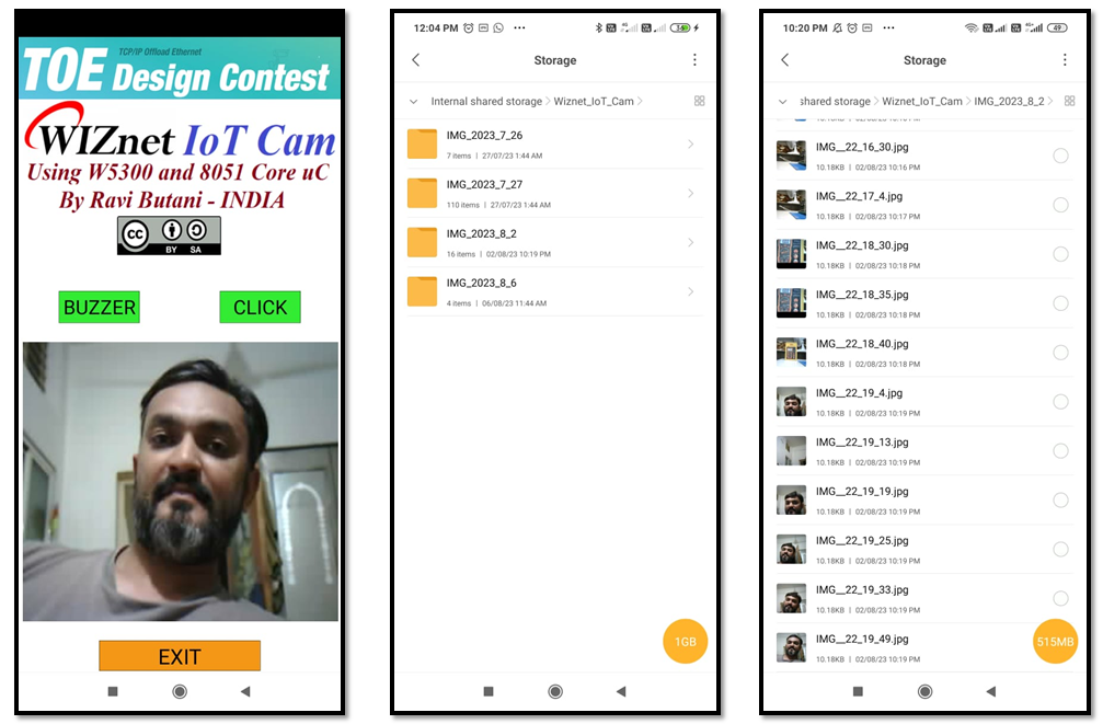
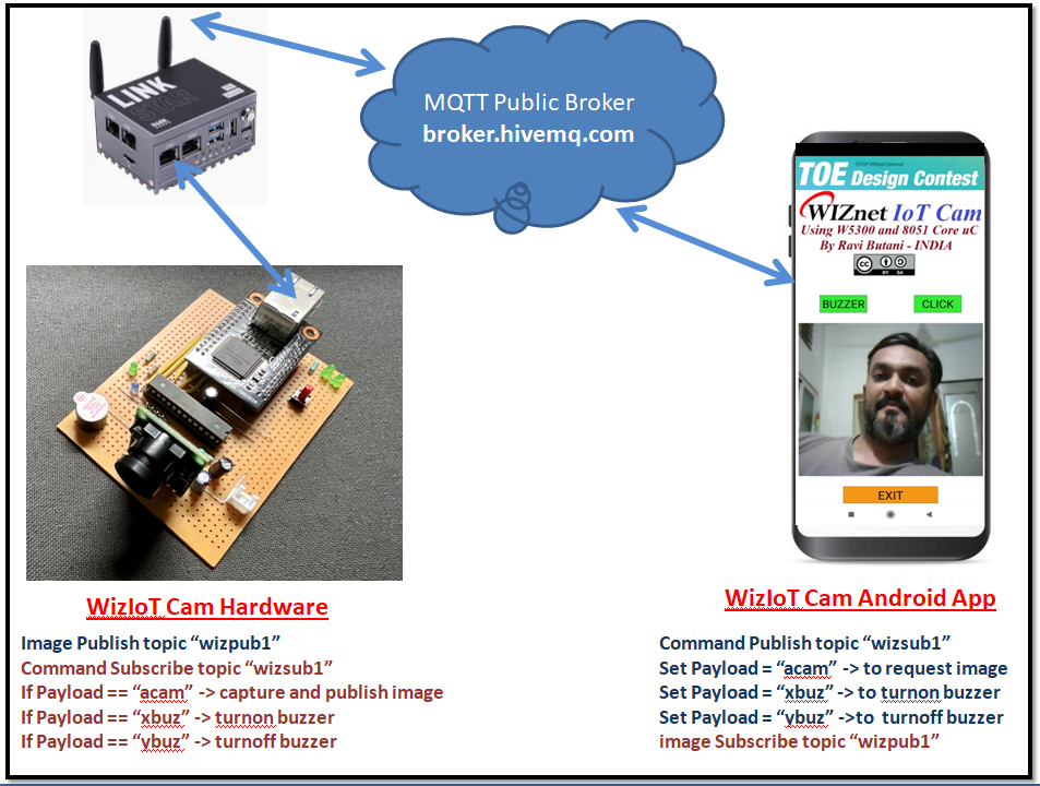
WizCam Android Application : WizIoTCam Android application is made using Processing For Android. Compiled Apk file and source code attached with this project for reference.
Application having following features,
- MQTT Client to receive raw JPEG image byte array and control Buzzer on board
- Display Latest Image received from Wizcam board on App main screen
- Save every image with time stamp to local storage of Android Device
- MQTT client and ketai third party library used in application
Following are few screen shot of app showing features..
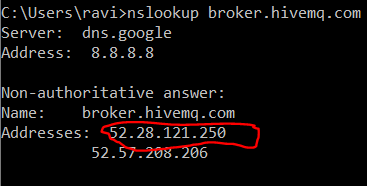
WizCam Setup : Attached Apk file is compiled for Broker.hivemq.com public MQTT broker, so any one can use it. topic names and payload description are shown in following figure.
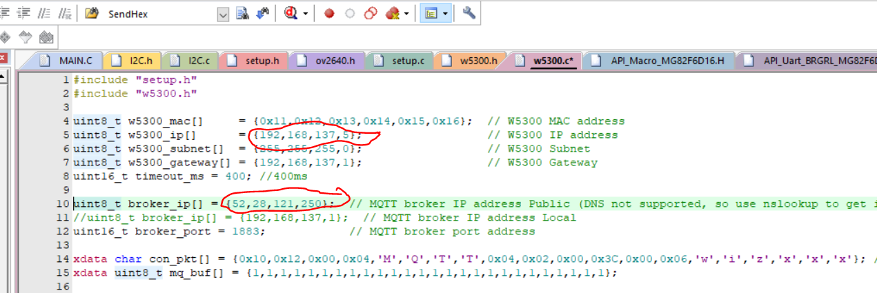
DNS is not implemented on WizIoT Cam board firmware so one need to use nslookup to find IP address of broker and need to modify following lines in MG82F6D16 firmware to update broker IP address given by nslookup and Local IP Address based on your local network settings as shown below..
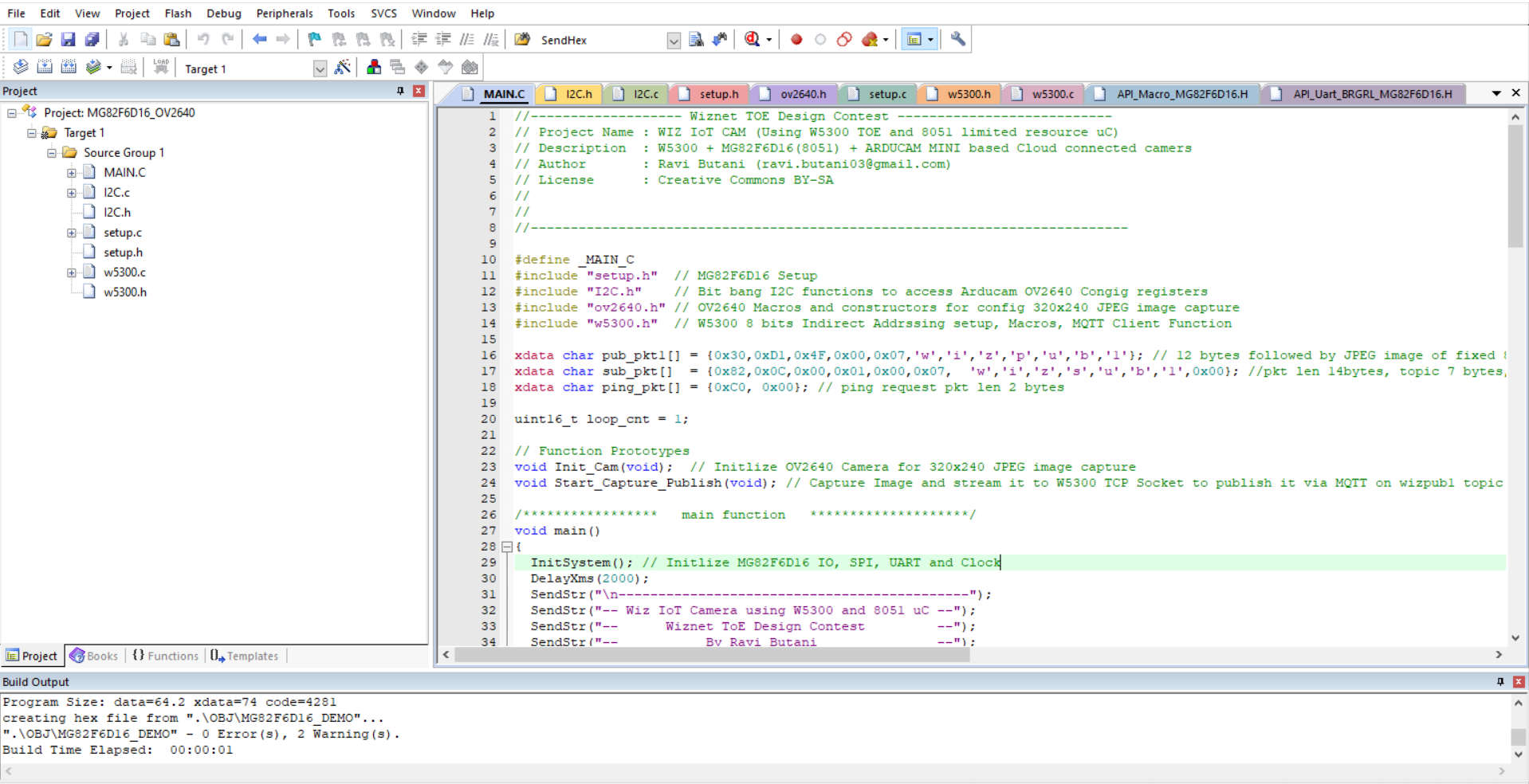
WizCam MG82F6D16 Firmware details :
- Keil-C51 or SDCC tool is compatible to compile this firmware
- No third party libraries used in this project, W5300 low level drivers and Ethernet setup functions, MQTT Client functions, OV2640 Arducam Camera related functions are developed from scratch just using data sheet.
- W5300 Indirect Addressing mode with 8 bit data bus used is used to reduce required pin count to only 14
- here is firmware folder tree
- MG82F6D16 Complete well commented firmware is attached with this project, It is meaningless to describe complete firmware here, but W5300 Low level IO drivers and important code snippets related to W5300 are as following, which can be modify and used for other micro controller as well.
- Code snippet to configure W5300 indirect addressing mode
// *******configure W5300 to work in 8 bit indirect addressing mode ********
void w5300_setup_indirect_MR(void)
{
	// Write 0x01 to MR_LOW (Addr - 0x01) for configure w5300 indirect addressing
	PORT_SetP1PushPull(0xFF);
	DATA = 0x01;
	A2=0; A1=0; A0=1;
  WR = 0; RD = 1; CS = 0;
	DelayXus(1);
  CS = 1;
	DelayXus(1);
}
- Code snippet to read W5300 Register
// ******************* W5300 read register 16 bit ***************************
uint16_t w5300_read_indirect(uint16_t addr)
{
  uint16_t datax =0;
  uint16_t data1 = 0;
  uint16_t data2 = 0;

  // set desired addr in indirect address reg 0x02, 0x03 address
	PORT_SetP1PushPull(0xFF);
  DATA = ((addr>>8) & 0xFF);
	A2=0; A1=1; A0=0;
  WR = 0; RD = 1; CS = 0;
	DelayXus(1);
  CS = 1;
	DelayXus(1);

	DATA = (addr & 0xFF);
	A2=0; A1=1; A0=1;
  WR = 0; RD = 1; CS = 0;
	DelayXus(1);
  CS = 1;
	DelayXus(1);

	PORT_SetP1OpenDrain(0XFF);
  DATA = 0xFF; // Set Data Bus input by keeping all pins open drain with weak pullup

  // read Data from indirect Data Register
  A2=1; A1=0; A0=0;
  WR = 1; RD = 0; CS = 0;
  DelayXus(2);
  data1 = DATA & 0xFF;
  CS = 1;
  DelayXus(1);

	A2=1; A1=0; A0=1;
  WR = 1; RD = 0; CS = 0;
  DelayXus(2);
  data2 = DATA & 0xFF;
  CS = 1;
  DelayXus(1);
	datax = (data1<<8)|data2;

	return datax;
}- Code snippet to write W5300 Register
// ******************* W5300 write register 16 bit ***************************
void w5300_write_indirect(uint16_t addr, uint16_t data1)
{
	// set desired addr in indirect address reg 0x02, 0x03 address
	PORT_SetP1PushPull(0xFF);
	DATA = ((addr>>8) & 0xFF);
	A2=0; A1=1; A0=0;
  WR = 0; RD = 1; CS = 0;
	DelayXus(1);
  CS = 1;
	DelayXus(1);

	DATA = (addr & 0xFF);
	A2=0; A1=1; A0=1;
  WR = 0; RD = 1; CS = 0;
	DelayXus(1);
  CS = 1;
	DelayXus(1);

  // set desired Data in indirect Data reg 0x04, 0x05 address
	DATA = ((data1>>8) & 0xFF);
	A2=1; A1=0; A0=0;
  WR = 0; RD = 1; CS = 0;
	DelayXus(1);
  CS = 1;
	DelayXus(1);

	DATA = (data1 & 0xFF);
	A2=1; A1=0; A0=1;
  WR = 0; RD = 1; CS = 0;
	DelayXus(1);
  CS = 1;
	DelayXus(1);
}- Code snippet to soft reset W5300
// ******************* W5300 Soft Reset ***************************
void w5300_reset(void)
{
	// Write 0x80 to MR_LOW (Addr - 0x01) for soft reset w5300
	PORT_SetP1PushPull(0xFF);
	DATA = 0x80;
	A2=0; A1=0; A0=1;
  WR = 0; RD = 1; CS = 0;
	DelayXus(1);
  CS = 1;
	DelayXus(1);
}- Code snippet to setup w5300 MQTT Client
// **** Setup W5300 Network Configuration and connect to MQTT Brokerm ****
void setup_mqtt_broker(void)
{
	DelayXms(1000);
	w5300_write_indirect(_RTR_,timeout_ms*10); // set retry timeout

  w5300_write_indirect(SHAR,w5300_mac[0]<<8 | w5300_mac[1]);  // Setup w5300 MAC Address
  w5300_write_indirect(SHAR+2,w5300_mac[2]<<8 | w5300_mac[3]);
  w5300_write_indirect(SHAR+4,w5300_mac[4]<<8 | w5300_mac[5]);

  w5300_write_indirect(SIPR,w5300_ip[0]<<8 | w5300_ip[1]);  // Setup w5300 IP Address
  w5300_write_indirect(SIPR+2,w5300_ip[2]<<8 | w5300_ip[3]);

  w5300_write_indirect(GAR,w5300_gateway[0]<<8 | w5300_gateway[1]);  // Setup w5300 Gateway Address
  w5300_write_indirect(GAR+2,w5300_gateway[2]<<8 | w5300_gateway[3]);

  w5300_write_indirect(SUBR,w5300_subnet[0]<<8 | w5300_subnet[1]);  // Setup w5300 Subnet Address
  w5300_write_indirect(SUBR+2,w5300_subnet[2]<<8 | w5300_subnet[3]);

  DelayXms(2000);

	SendStr("opening socket");
  w5300_write_indirect( Sn_CR(0), Sn_CR_CLOSE);
  DelayXms(1000);
  w5300_write_indirect( Sn_MR(0), Sn_MR_TCP); /* sets TCP mode */
  w5300_write_indirect( Sn_PORTR(0), 0xF450); /* sets source port number */
  w5300_write_indirect( Sn_CR(0), Sn_CR_OPEN);
  DelayXms(1000);

  w5300_write_indirect(Sn_DIPR(0),  broker_ip[0]<<8 | broker_ip[1]);
  w5300_write_indirect(Sn_DIPR(0)+2,broker_ip[2]<<8 | broker_ip[3]);
  w5300_write_indirect(Sn_DPORT(0), broker_port);
  w5300_write_indirect( Sn_CR(0), Sn_CR_CONNECT);
  DelayXms(1000);

  while((w5300_read_indirect(Sn_SSR(0))&0xFF) != SOCK_ESTABLISHED)
  {
		LED_G = 1;
    SendStr("Attempting connection to broker");
    DelayXms(50);
		LED_G = 0;
		DelayXms(450);
  }
	SendStr("Sending Con pkt..");
  write_broker(con_pkt, 20);
  SendStr("Connected to broker");
  DelayXms(1000);
}- Important Ethernet and MQTT initialization
uint8_t w5300_mac[]     = {0x11,0x12,0x13,0x14,0x15,0x16}; 	// W5300 MAC address
uint8_t w5300_ip[]      = {192,168,137,5};      						// W5300 IP address
uint8_t w5300_subnet[]  = {255,255,255,0};  								// W5300 Subnet
uint8_t w5300_gateway[] = {192,168,137,1};  								// W5300 Gateway
uint16_t timeout_ms = 400; //400ms

//uint8_t broker_ip[] = {3,77,70,149};  // MQTT broker IP address Public (DNS not supported, so use nslookup to get ip of public broker and paste here)
uint8_t broker_ip[] = {192,168,137,1};  // MQTT broker IP address Local
uint16_t broker_port = 1883;  					// MQTT broker port address

xdata char con_pkt[] = {0x10,0x12,0x00,0x04,'M','Q','T','T',0x04,0x02,0x00,0x3C,0x00,0x06,'w','i','z','x','x','x'}; //pkt len 20bytes, CID 6 bytes
xdata char pub_pkt1[] = {0x30,0xD1,0x4F,0x00,0x07,'w','i','z','p','u','b','1'}; // 12 bytes followed by JPEG image of fixed 8180+2000 bytes, Pub Topic wizpub1
xdata char sub_pkt[]  = {0x82,0x0C,0x00,0x01,0x00,0x07,  'w','i','z','s','u','b','1',0x00}; //pkt len 14bytes, topic 7 bytes, Sub Topic wizsub1
xdata char ping_pkt[] = {0xC0, 0x00}; // ping request pkt len 2 bytes
w5300_write_indirect(TMS01R,0x0C04); // Socket TX memory set to 12KB to manage 320x240 JPEG imageWizCam UART Debug Console :
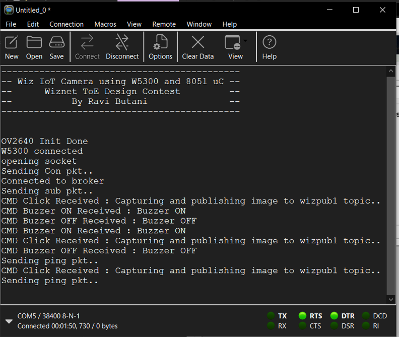
Conclusion : It was lot of fun while building this project and playing with W5300, Really hopes that readers and one who wants to replicate this project have similar fun while playing with W5300 ......
Cheers :)
Ravi
-
Wiz IoT Cam MG82F6D16 Firmware
MG82F6D16 (Microcontroller) Firmware for Build Using Keil C51 (SDCC can be also used)


-
Wiz IoT Cam Connection diagram
Wiz IoT Cam Connection diagram
-
Wiz IoT Cam Pin Mapping
Wiz IoT Cam Pin Mapping
-
Wiz IoT Cam Android Application Source Code
Wiz IoT Cam Android Application Source code compiled using processing for Android
-
Wiz IoT Cam Android Application APK
Wiz IoT Cam Android Application APK File compiled using processing for Android