
TDS monitor
2018 I have already built a project Simple Water Quality Analysis using Arduino MKR1000.
I want to try porting it to other boards.
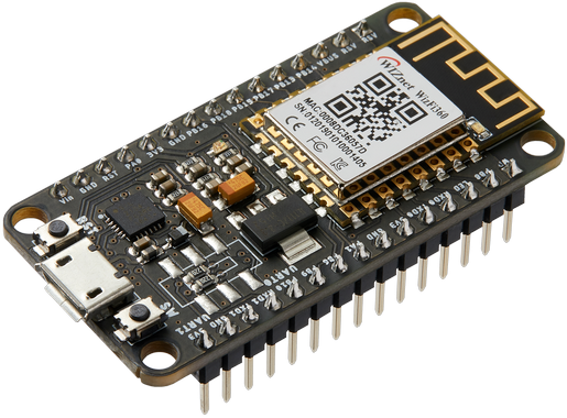
WIZnet - WizFi360-EVB-Mini
x 1
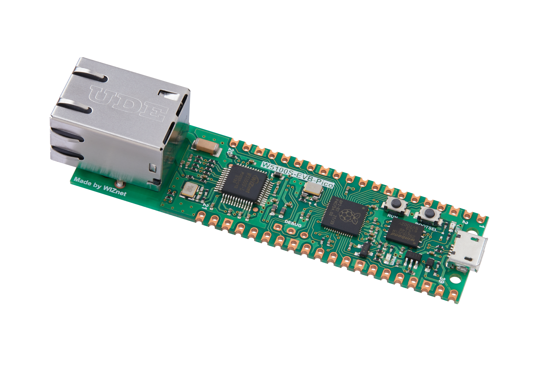
WIZnet - W5100S-EVB-Pico
x 1

Arduino - Arduino IDE
x 1
adafruit - Adafruit IO
x 1
Feeds
Story
What is TDS(Total Dissolved Solids)?
From the Wikipedia link below.
https://en.wikipedia.org/wiki/Total_dissolved_solids
"Total dissolved solids (TDS) is a measure of the dissolved combined content of all inorganic and organic substances present in a liquid in molecular, ionized, or micro-granular (colloidal sol) suspended form. TDS concentrations are often reported in parts per million (ppm). Water TDS concentrations can be determined using a digital meter."
Importance of TDS
TDS is one of the water quality indicators. In addition to TDS, a complete water quality test must also detect microbial indicators, toxicological indicators, sensory characteristics, and other indicators.
I already make the WEBserver-type project on hackster.io. Now I want to send the data to the cloud using WizFi360.
Hardware
WizFi360-EVB-Mini * 1
W5100S-EVB-Pico *1
Dupont Line * 4
2P 2.54mm connector Line * 1
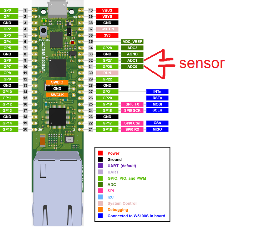
sensor plate*1
Software
Arduino IDE 1.18.19 or 2.0.1
Arduino boards package: Raspberry Pi Pico/RP2040 2.6.2
WizFi360_arduino_library
Pretest
Initially, I wanted to use only the WizFi360-EVB-Mini module to complete the project. But I found that the program of the module is very complicated and the information is not complete.
So I have to use another module to work with WizFi360-EVB-Mini, here I selected W5100S-EVB-Pico.
The picture below is the command and flow of my WizFi360-EVB-Mini using MQTT to connect to adafruit.IO.
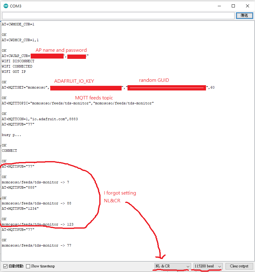
The test result as below pic.
Project setting
WizFi360 setting
After pre-testing, I am sure my adafruit.IO and WizFi360-EVB-Mini are ready.
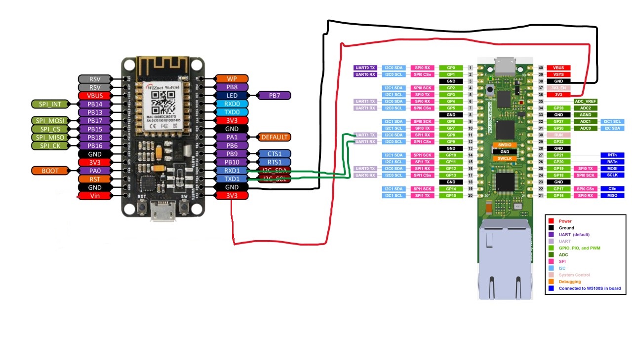
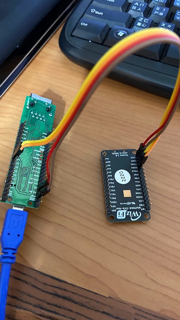
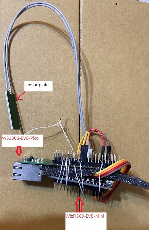
Now, I want to connect W5100S-EVB-Pico and WizFi360-EVB-Mini.
Here I found a hardware problem, there is no switch in WizFi360-EVB-Mini WizFi360 UART1, connected to CP2104 UART via 22R.
There may be problems if I connect the PICO directly.
I refer to "How to add WizFi360-EVB-Mini to Raspberry Pi Pico-(Python)"
It looks like it's working, maybe the CP2104 doesn't have a power supply so it's ok.
So I followed it to connect.
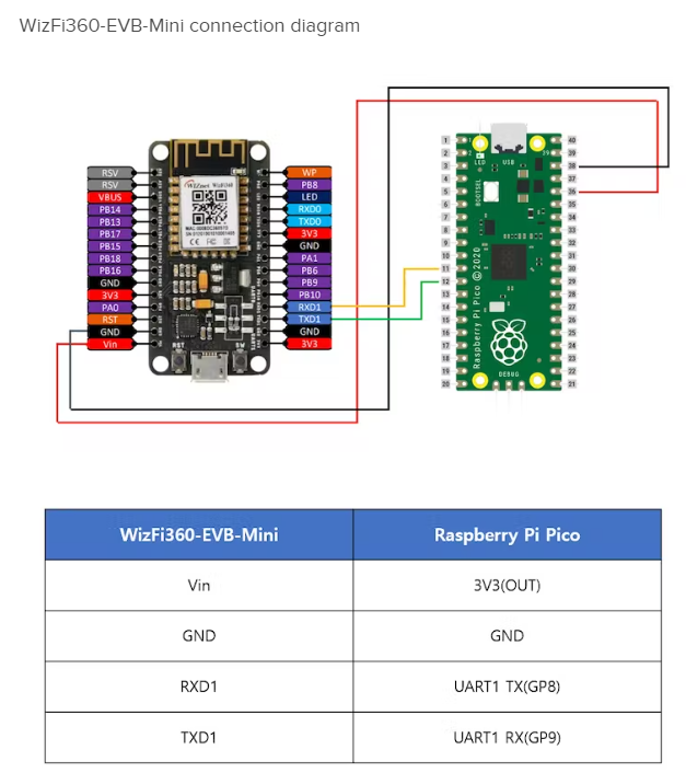
Since I use W5100S-EVB-Pico.
Note. if connect 3V3 to Vin it will be hard to connect to AP.
Code for WizFi360
After a few days of adjustment and testing, finally connected the W5100S-EVB-Pico and WizFi360-EVB-Mini to adafruit.IO.
For using the Arduino IDE to the program W5100S-EVB-Pico please follow earlephilhower's GitHub.
Here are some tips.
1. use Wiznet library The official library has fixed some errors.
2. Print out the module log for debugging
	// Change _WIZFILOGLEVEL_ to set tracing and logging verbosity
// 0: DISABLED: no logging
// 1: ERROR: errors
// 2: WARN: errors and warnings
// 3: INFO: errors, warnings and informational (default)
// 4: DEBUG: errors, warnings, informational and debug

#ifndef _WIZFILOGLEVEL_
#define _WIZFILOGLEVEL_ 4
#endif
3. Adjust the program according to the "WizFi360 AT Instruction Set" PDF
The following is AT command MQTT function I edited.
	//MQTTSET AT+MQTTSET=<UserName>,<Password>,<ClientID>,<AliveTime>
bool WizFi360Drv::mqttset(const char* UserName, const char* Password,const char* ClientID,int AliveTime)
{
	LOGDEBUG(F("> mqttset"));

	int aliveTime;
	if(AliveTime>300)
	{
		aliveTime = 300;
	}
	else if(AliveTime<30)
	{
		aliveTime = 30;
	}
	else
	{
		aliveTime = AliveTime;
	}

	// TODO
	// Escape character syntax is needed if "SSID" or "password" contains
	// any special characters (',', '"' and '/')

    // connect to access point, use CUR mode to avoid connection at boot
	int ret = sendCmd(F("AT+MQTTSET=\"%s\",\"%s\",\"%s\",\"%d\""), 1000, UserName, Password, ClientID, aliveTime);

	if (ret==TAG_OK)
	{
		LOGINFO(F("set MQTT"));
		return true;
	}
	LOGWARN(F("Failed set MQTT"));
	// clean additional messages logged after the FAIL tag
	delay(1000);
	wizfi360EmptyBuf(false);
	return false;
}

//MQTTTOPIC AT+MQTTTOPIC=<publish_topic>,<subscribe_topic1>
bool WizFi360Drv::mqtttopic(const char* publish_topic, const char* subscribe_topic1)
{
	LOGDEBUG(F("> mqtttopic"));

	// TODO
	// Escape character syntax is needed if "SSID" or "password" contains
	// any special characters (',', '"' and '/')

    // connect to access point, use CUR mode to avoid connection at boot
	int ret = sendCmd(F("AT+MQTTTOPIC=\"%s\",\"%s\""), 1000, publish_topic, subscribe_topic1);

	if (ret==TAG_OK)
	{
		LOGINFO(F("set mqtttopic"));
		return true;
	}
	LOGWARN(F("Failed set mqtttopic"));
	// clean additional messages logged after the FAIL tag
	delay(1000);
	wizfi360EmptyBuf(false);
	return false;
}

//MQTTCON AT+MQTTCON=<enable>,<broker_IP>,<broker_port>
bool WizFi360Drv::mqtttcon(int enable,const char* broker_IP, int broker_port)
{
	LOGDEBUG(F("> mqtttcon"));

	// TODO
	// Escape character syntax is needed if "SSID" or "password" contains
	// any special characters (',', '"' and '/')

    // connect to access point, use CUR mode to avoid connection at boot
	int ret = sendCmd(F("AT+MQTTCON=%d,\"%s\",%d"), 60000, enable,broker_IP, broker_port);

	if (ret==TAG_OK)
	{
		LOGINFO1(F("connect to"),broker_IP);
		return true;
	}
	LOGWARN1(F("Failed connect to"),broker_IP);
	// clean additional messages logged after the FAIL tag
	delay(1000);
	wizfi360EmptyBuf(false);
	return false;
}

//MQTTPUB AT+MQTTPUB=<message>
bool WizFi360Drv::mqtttpub(const char* message)
{
	LOGDEBUG(F("> mqtttpub"));

	// TODO
	// Escape character syntax is needed if "SSID" or "password" contains
	// any special characters (',', '"' and '/')

    // connect to access point, use CUR mode to avoid connection at boot
	int ret = sendCmd(F("AT+MQTTPUB=\"%s\""), 1000, message);

	if (ret==TAG_OK)
	{
		LOGINFO1(F("pub:"),message);
		return true;
	}
	LOGWARN1(F("Failed pub"),message);
	// clean additional messages logged after the FAIL tag
	delay(1000);
	wizfi360EmptyBuf(false);
	return false;
}
From connecting to publish code as below.
	bool UpLoadToAdafruit(int sensorvalue)
{
  int ret;

  // check for the presence of the shield
  if (WiFi.status() == WL_NO_SHIELD) {
    Serial.println("WiFi shield not present");
    // don't continue
    while (true);
  }
  while ( status != WL_CONNECTED) {
    Serial.print("Attempting to connect to WPA SSID: ");
    Serial.println(SECRET_SSID);
    // Connect to WPA/WPA2 network
    status = WiFi.begin(SECRET_SSID, SECRET_PASS);
  }

  // you're connected now, so print out the data
  Serial.println("You're connected to the network");

//  printWifiStatus(); //frozen here

  Serial.println("Start MQTT");

  wizfi360Drv.mqttset(MQTT_Username, MQTT_Password,MQTT_GUID, 60);
  wizfi360Drv.mqtttopic(MQTT_TOPIC, MQTT_TOPIC);
  wizfi360Drv.mqtttcon(1,MQTT_Host, MQTT_Port);

  char cstr[16];
  itoa(sensorvalue, cstr, 10); //change int to string
  wizfi360Drv.mqtttpub(cstr);

  return true;
}
Need to define the following depending on the environment.
#define SECRET_SSID "SECRET_SSID "
#define SECRET_PASS "SECRET_PASS "
#define MQTT_Username "MQTT_Username "
#define MQTT_Password "MQTT_Password "
#define MQTT_GUID "MQTT_GUID "
#define MQTT_TOPIC "MQTT_TOPIC "
#define MQTT_Host "io.adafruit.com"
#define MQTT_Port 8883
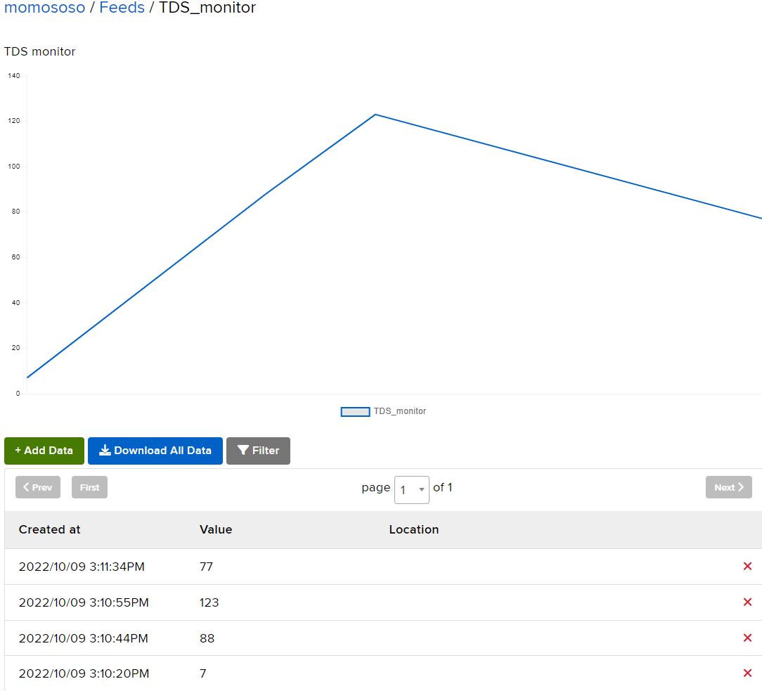
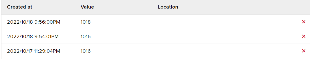
Follow Adafruit IO MQTT API and Welcome to Adafruit IO to setting feeds.
See the data upload successfully on the adafruit.IO website
Sensor setting
Similarly, with my old project, the sensor is two metal planes or pins. But this time without another analog pin for reading and doesn't need pull-up resistors.
I use RP2040 internal pull-up/pull-down and use the sensor pins to direct read. This function needs to adjust the Arduino-pico library's ADC initial and analog read functions.
	//modify ADC init with pull
#include <Arduino.h>
#include <CoreMutex.h>
#include <hardware/gpio.h>
//#include <hardware/pwm.h>
#include <hardware/clocks.h>
#include <hardware/pll.h>
#include <hardware/adc.h>
static bool adcInitted = false;
auto_init_mutex(_adcMutex);
static int _readBits = 10;
void adc_gpio_init_WithPull(uint gpio) {
  invalid_params_if(ADC, gpio < 26 || gpio > 29);
  // Select NULL function to make output driver hi-Z
  gpio_set_function(gpio, GPIO_FUNC_NULL);

  //    gpio_disable_pulls(gpio); //modify ADC init with pull
  gpio_set_input_enabled(gpio, false);
}
int analogReadWithPull(pin_size_t pin) {
  CoreMutex m(&_adcMutex);

  pin_size_t maxPin = max(A0, A3);
  pin_size_t minPin = min(A0, A3);

  if ((pin < minPin) || (pin > maxPin) || !m) {
    DEBUGCORE("ERROR: Illegal analogRead pin (%d)\n", pin);
    return 0;
  }
  if (!adcInitted) {
    adc_init();
    adcInitted = true;
  }
  adc_gpio_init_WithPull(pin); //modify ADC init with pull
  adc_select_input(pin - minPin);
  return (_readBits < 12) ? adc_read() >> (12 - _readBits) : adc_read() << (_readBits - 12);
}
//modify ADC init with pull
Test read and print out.
	void loop() {
  // start
  digitalWrite(ledPin, HIGH);
  //INPUT_PULLUP INPUT_PULLDOWN
  //port LH
  pinMode(port1, INPUT_PULLDOWN);
  pinMode(port2, INPUT_PULLUP);
  sensorValue2 = analogReadWithPull(port1);
  pinMode(port1, INPUT_PULLDOWN);
  pinMode(port2, INPUT_PULLUP);
  sensorValue6 = analogReadWithPull(port2);
  delay(delaytime);

  digitalWrite(ledPin, LOW);

  //port HL
  pinMode(port1, INPUT_PULLUP);
  pinMode(port2, INPUT_PULLDOWN);
  sensorValue4 = analogReadWithPull(port1);
  pinMode(port1, INPUT_PULLUP);
  pinMode(port2, INPUT_PULLDOWN);
  sensorValue8 = analogReadWithPull(port2);
  delay(delaytime);

  Serial.printf("LH1:%d,HL1:%d,LH2:%d,HL2:%d\r\n", sensorValue2, sensorValue4, sensorValue6, sensorValue8);
}
Sensor pretest video
About sensor
Unlike the last time using the pin header as a sensor.
This time switch to a discarded two-layer PCB.
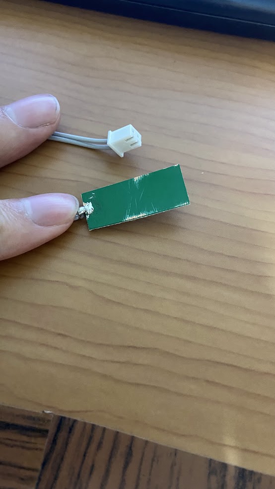
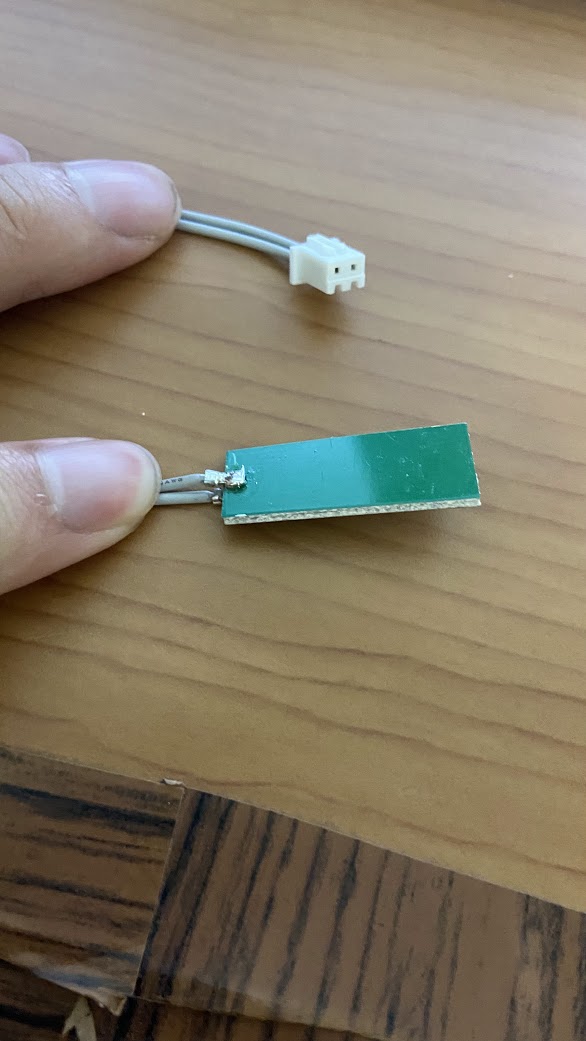
sensor connect to W5100S-EVB-Pico AD0/AD1(GP26/GP27)
Combine and Result
Hardware combine
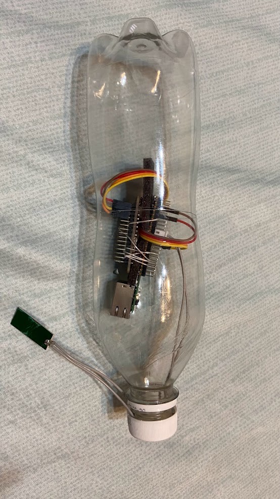
I want to put the whole project in a bottle, I have to reduce the space.
Here, the two boards are directly tied in reverse, and a foam block is used in the middle to avoid short circuits.
code combine
Combining code is easy just call the upload function and upload the sensor value.
UpLoadToAdafruit(sensorValue8);After running for a few times, I found that MQTT publish is not always successful. If the wifi disconnect when MQTT connect it will fail to publish.
That I adjust connect and publish code. Add mqtttdiscon function.
//MQTT dissconnect AT+MQTTDIS
bool WizFi360Drv::mqtttdiscon(void)
{
	LOGDEBUG(F("> mqtttdiscon"));

	// TODO
	// Escape character syntax is needed if "SSID" or "password" contains
	// any special characters (',', '"' and '/')

    // connect to access point, use CUR mode to avoid connection at boot
	int ret = sendCmd(F("AT+MQTTDIS"));

	if (ret==TAG_OK)
	{
		LOGINFO(F("Disconnects from a Broker"));
		return true;
	}
	LOGWARN(F("Failed Disconnects from a Broker"));
	// clean additional messages logged after the FAIL tag
	delay(1000);
	wizfi360EmptyBuf(false);
	return false;
}
Connect and publish three times.
    //sometimes wifi disconnect make pub fail
  for (int i = 0; i < 3; i++)
  {
    Serial.println("Start MQTT connect");
    wizfi360Drv.mqtttcon(1, MQTT_Host, MQTT_Port);
    char cstr[16];
    itoa(sensorvalue, cstr, 10); //change int to string
    Serial.println("Start MQTT pub");
    wizfi360Drv.mqtttpub(cstr);
    wizfi360Drv.mqtttdiscon();

  }
  WiFi.disconnect();
Put boards into PET bottle
Buy a cola PET bottle, and drink out of it. After washing and drying, cut it from the middle.
Put the board in and let the sensor come out of the bottle.
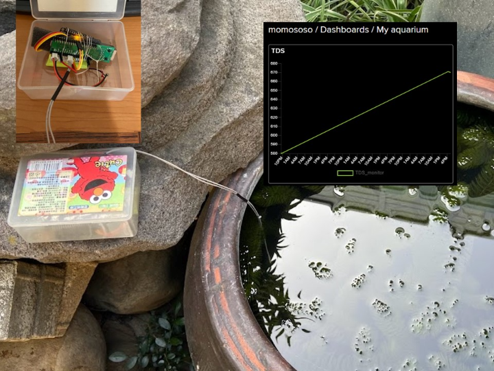
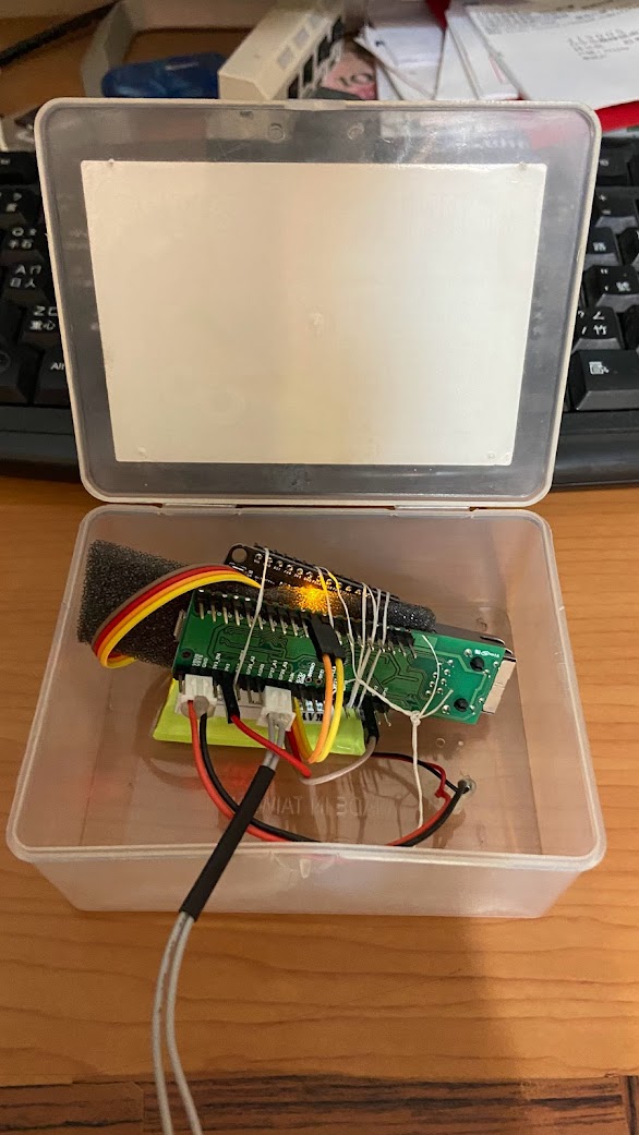
Put boards into PET Box
I found a disuse cotton swab PET box it looks very suit for the demo.
Final demo code adjust
If sensor values are published too frequently, cloud memory and network bandwidth are wasted. I added a long delay at the end of the loop. But this wastes electric power. I've been looking for the RP2040 pico/WizFi360 long sleep feature.
UpLoadToAdafruit(sensorValue8);
delay(7200000); // delay 2 hour
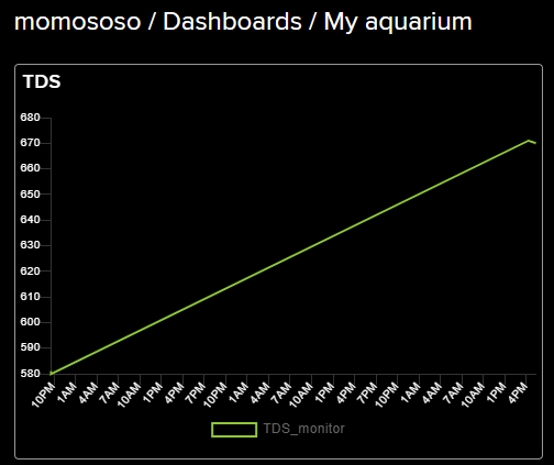
board.restart();Demo Picture
I put sensors in my aquarium to monitor water quality.

Conclusion and Review
1. Thanks to Wiznet for providing WizFi360-EVB-Mini development boards.
2. I should select WizFi360-EVB-Pico as a sample board. WizFi360-EVB-Mini is very suited for AT command pretest and debugging but when fully project it will spend more than WizFi360-EVB-Pico or a user-designed board.
3. The sensor value needs to be calibrated. Since this is the cheapest solution for the TDS monitor the matching curve may be higher than the quadratic equation. Or you can use TDS module Gravity or Grove.
4. For power consumption, please wait for the Arduino library to update the deep sleep function or change to using micro-python.
I measured the total system current was 92mA. After I slow down the RP2040 CPU clock to 50MHz(133MHz original) the current was down to 80mA and I pull down the WizFi360 reset pin which was 61mA. That means RP2040 consumes the most power. I will use WizFi360 with other MCU boards like STM32/NXP/Nuvoton next project.
5. I've spent a lot of time researching "sending data via webhooks". But still can't post messages. Hope there will have an example or AT command that can do it.
6. Maybe the official can add the MQTT function into Arduino libraries.
-
Fully arduino code
setting your AP and information at arduino_secrets.h

-
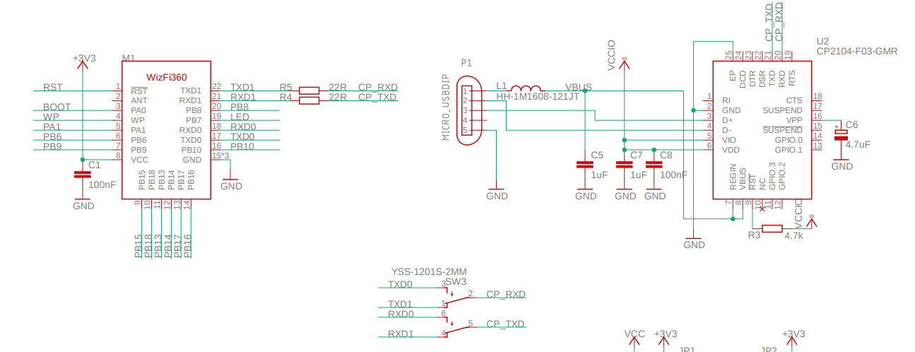
WizFi360-EVB-Mini
WizFi360-EVB-Mini Schematic

-
W5100S-EVB-Pico
W5100S-EVB-Pico Schematic