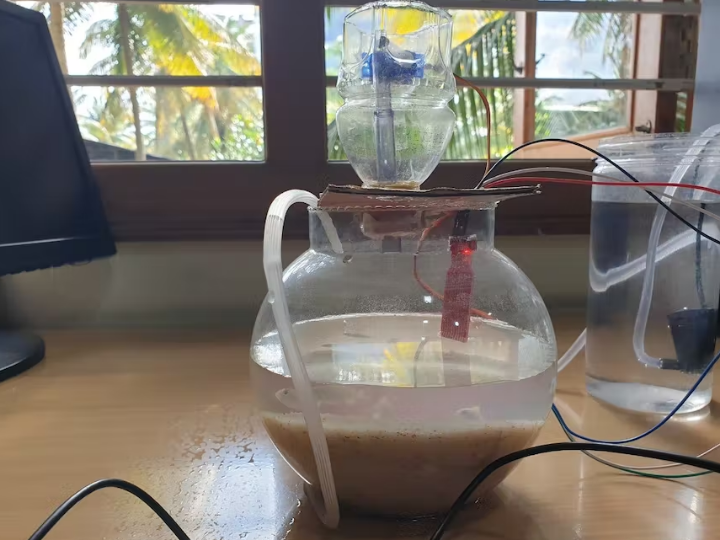
[AIoT] Smart Aquarium with Voice Recognition
This project has 3 main functionalities: timed fish feeding using voice control, water pumping, and water level monitoring.

Adafruit - SG90 Micro-servo motor
x 1
seedstudio - Seeed Studio Grove - Relay
x 1
seedstudio - Seeed Studio Grove - Water Sensor
x 1
1. Introduction
The aquarium system now on the market is a standard aquarium. The aquarium system on the market today is already interesting, with a collection of plants and fish in the tank, but the issues if the aquarium is kept indoors the issue is still-manual distribution of fish feed. At least once a day, aquarium owners must personally feed their fish. This is especially problematic if the aquarium owner is extremely busy, as the danger of forgetting to feed the fish is very high.To overcome the existing issues, an aquarium system that is both visually appealing and entirely automated in terms of water-filling and fish feeding when required. A smart aquarium system that can accommodate aquarium hobbyists and all of the aquarium owner's activities.One of the technologies designed to make it easier for humans to monitor and control an internet-based system is IoT technology. The Internet of Things (IoT) is a system in which things are given unique identities and the ability to move data over a network without requiring human-to-human or human-to-computer interaction in both directions. This technology is supposed to aid in the monitoring of fish they grow.The goal of this project is to make aquarium monitoring and maintenance easier. Using the Picoboard, tasks like, testing water level, fish feeding, water pumping etc., can be automated. This project has 3main functionalities: timed fish feeding using a real-time clock, water pumping, and water level monitoring.. There is Ethernet connectivity, where the Ethernet module acts as a server and it communicates with the picoboard over serial and mobile device over local network. You can control and monitor the smart aquarium via the android app MQTT voice. The app will allow you to control the feeding the fish automatically when its required.
2. Components
- Tools used to make this model are:
- W5100S-EVB-Pico
- Android device.
- Servo Motor.
- Single channel Relay – 5V.
- Breadboard.
- Aquarium Bowl (For implementation).
- Wires, Resistors, led etc.
- Male to Female, Female to Female Breadboard Jumper wires.
- Water Level Sensor.
- Automatic feeder system.
- 5v pump
- Dc jack
- 5v adaptor
2.1.1. W5100S-EVB-PicoThe W5100S-EVB-Pico is a micro controller evaluation board based on the Raspberry Pi RP2040andthefully
hardwired TCP/IP controller W5100S. It functions similarly to the Raspberry Pi Pico board but adds Ethernet via the W5100S.
2.1.2 Android Device
Basically an android phone as an interface to work with the application to control the feeding functions of the smart aquarium.
2.1.3. Single Channel Relay Module
The 1-Channel Relay Driver Module is a load tripping mechanism used to derive load based on setting. It can operate on 5V, this makes it compatible. A 1-channel relay is an elector-mechanical relay operated on an electrical signal provided to it. Switches inside the relay make it useful for quick switching of load.
2.1.4 Servo motor
A servo motor is a rotary actuator that allows for precise control of angular position. It consists of a motor coupled to a sensor for position feedback.
2.1.5 Water level SensorTo detect the required water level in the aquarium.
2.1.6 (5V )Water pumpThe 5v pump helps in pumping the water to the aquarium.
3. Code Explanation:
The code starts with including all the libraries required for the components. All global variables and definitions for the MQTT server are initialized(Line no 14-19). Followed by form line no 22 - 44 MQTT callback function which is used for checking for new messages which is sent by publisher. In line 40 passing a keyword feed/Feed so when the publisher/user gives the command feed/Feed then the feeder will start working. Line no 47-60 MQTT reconnect callback. Line no 64-103 is of Ethernet connection, It tries to connect to the Ethernet, but if there are any problems, it sends a warning message to the serial port. Line 105-116 void setup(), this function in which we are setting the data pin for servo motor. Pin mode for pump, red led, buzzer. Line 118-136, int start_servo function telling servo to go to position in variable ‘pos’. To for loop conditions one goes from 0 degrees to 180 degrees another goes from 180 degrees to 0 degrees. Line 139-174 void loop() function, it contains the if condition to check for MQTT connection is connected to subscribe “home”. Then if condition to pump the water to start if water is less in fish bowl with buzzer high and to stop pumping water if water has reached maximum level with red led glowing to indicate maximum water level has reached.
4.AI Implementation
The AI implemented by voice recognition for the smart aquarium, is to automate the feeding system for the fish. We have used a raspberry pi local MQTT server for in-taking voice command and to activate feeder system. Firstly downloaded a MQTT voice app from play store. Then we have give the credentials MQTT Server:Port and MQTT Topic. MQTT Server:Port where the IP address and port number has to given. MQTT topic foe this project is “home”.
By clicking on the mic we need to send command feed/Feed so that the feeder gets activated. The given command will be checked if its matching with the command given in code, when it matches feeder gets activated.
YouTube
