
Remote Control Tower: Control infrared devices by "Hey Siri" (POE+PICO)
How to use Remote Control Tower: "Hey siri, Please open dyson fan","Hey siri, Increase the air volume of Dyson fan","Hey siri, please open the TV".

Raspberry Pi - RP2040
x 1
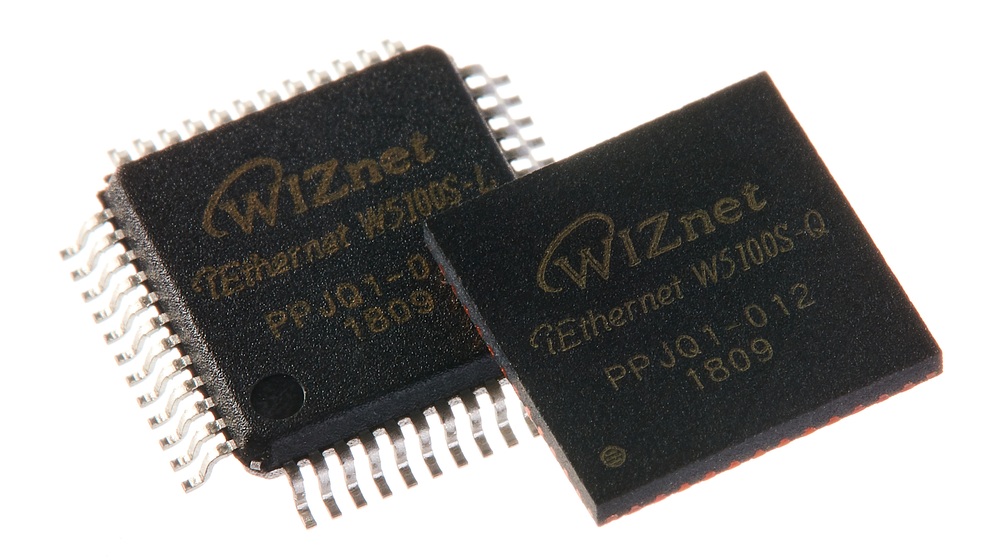
WIZnet - W5100S
x 1

adafruit - NeoPixel Ring: WS2812 5050 RGB LED
x 1

Arduino - Arduino IDE
x 1
blynk - Blynk
x 1

Apple - Shortcuts
x 1
Remote Control Tower is a network infrared remote control project. The purpose of doing this project is that there are many infrared remote controls at home, and there are always need to use the remote control but can't find it.
In this project, I want to control infrared remote control home appliances through Apple's "Siri" instead of using Homekit.
Test video controlled using "Hey Siri".
Test video controlled using Paper clips.
Video link below:
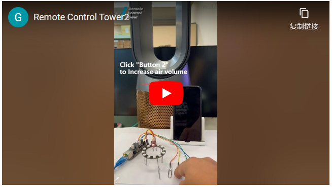
https://www.youtube.com/shorts/TdvhLQK3T70
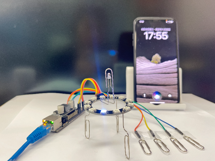
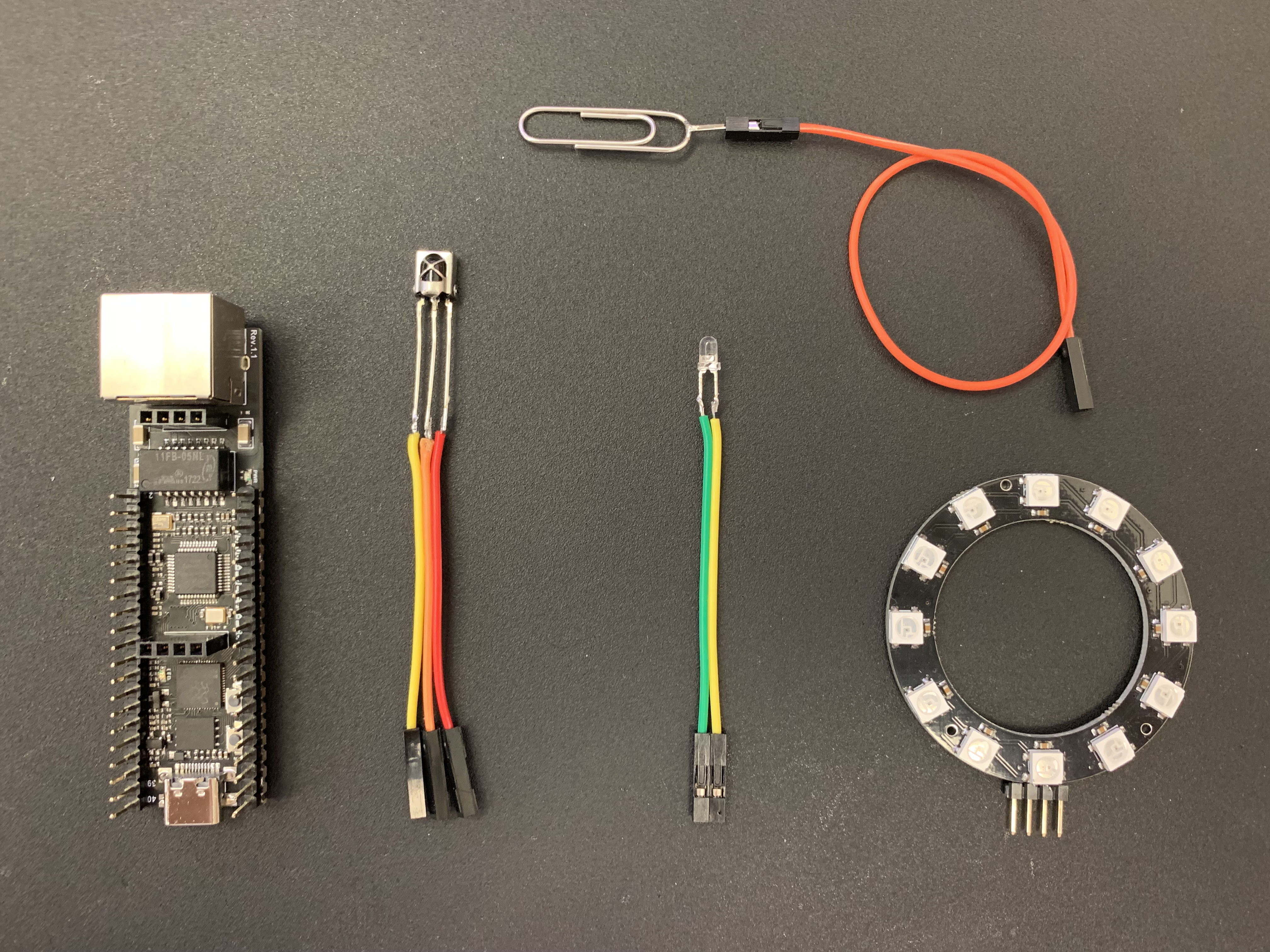
The premise of this project is to use the simplest components, add the network, and explore more interesting ways of using it. The previous Light Tower project used a WS2812 light ring and a paper clip as a touch button. This time the Remote Control Tower uses 4 paper clips as touch buttons, a WS2812 light ring as a status indicator, and an infrared transmitter to control other devices; all components used are shown in the figure below.
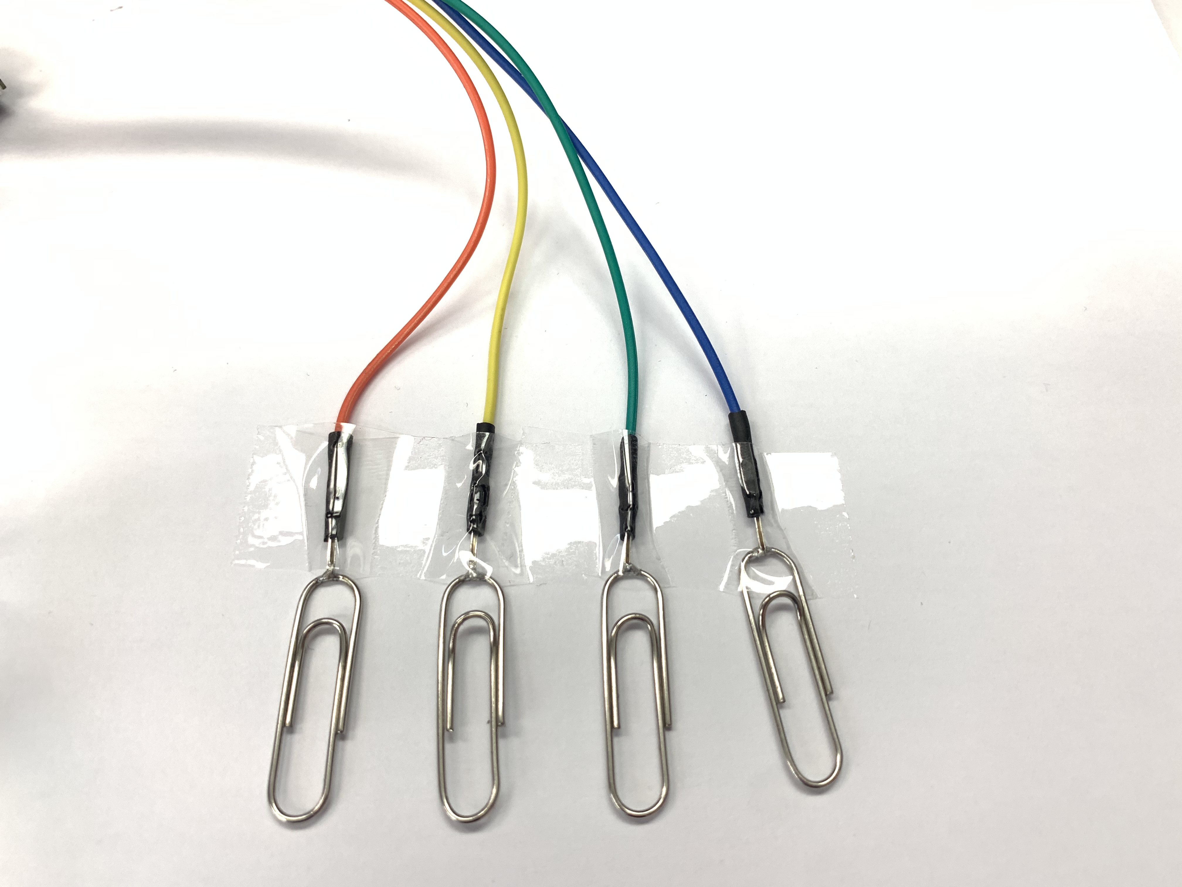
In order to make this project more interesting, I used a few paper clips to make a bracket for the Remote Control Tower.
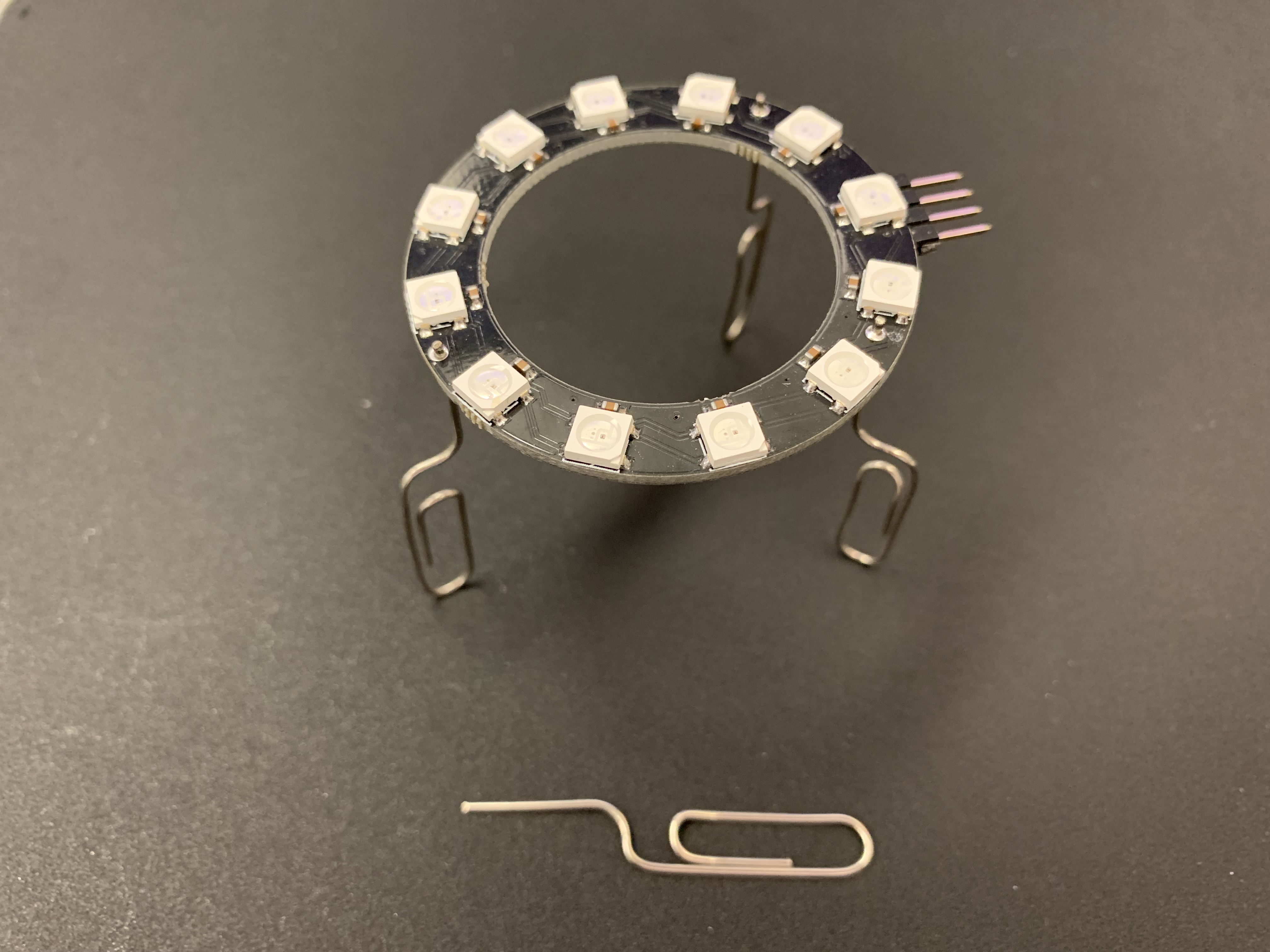
In order to have good infrared control effect, I placed the infrared transmitter at the highest point and made a protective structure with paper clips.
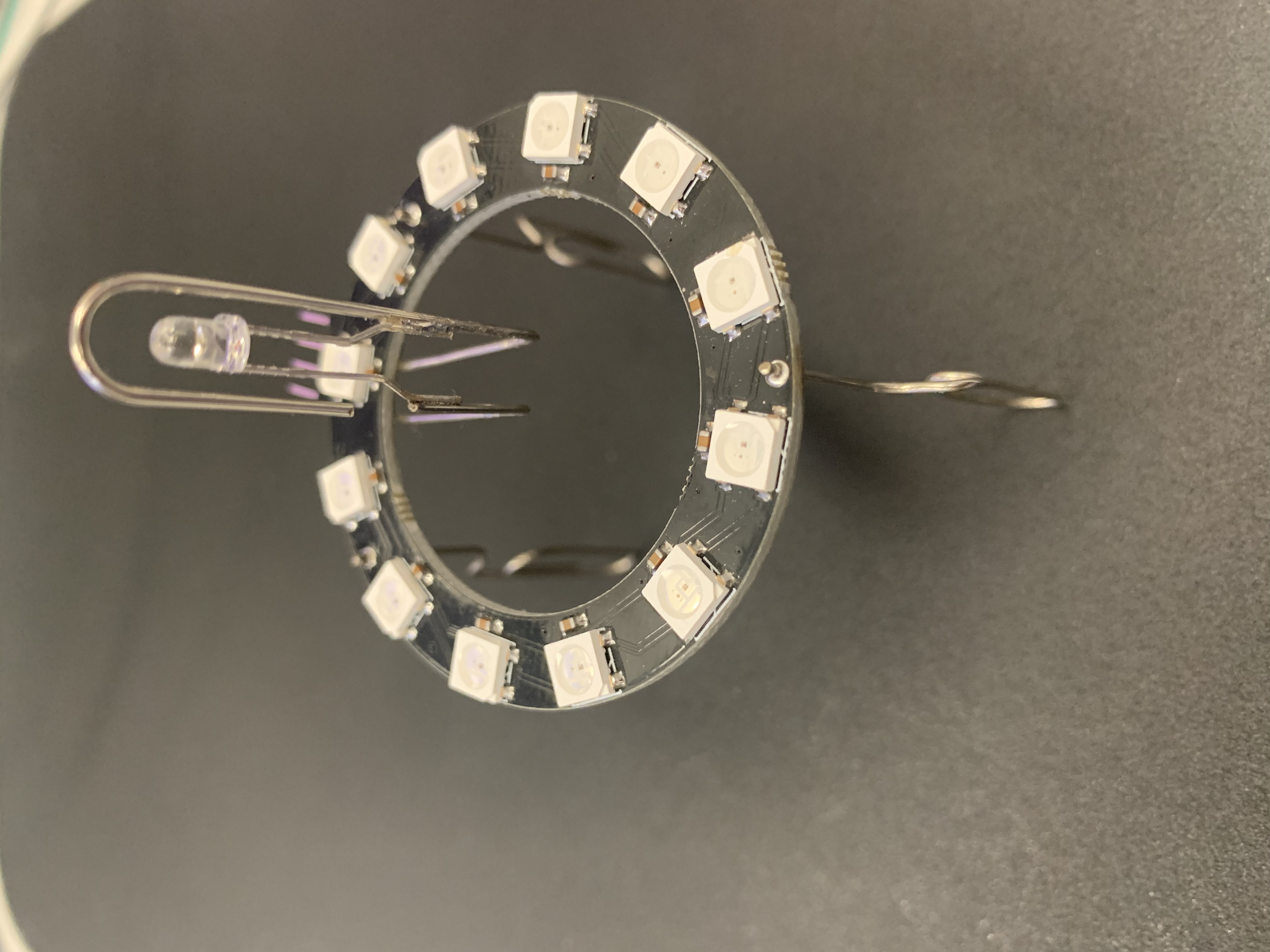
The final appearance is as follows, I am very satisfied with it.
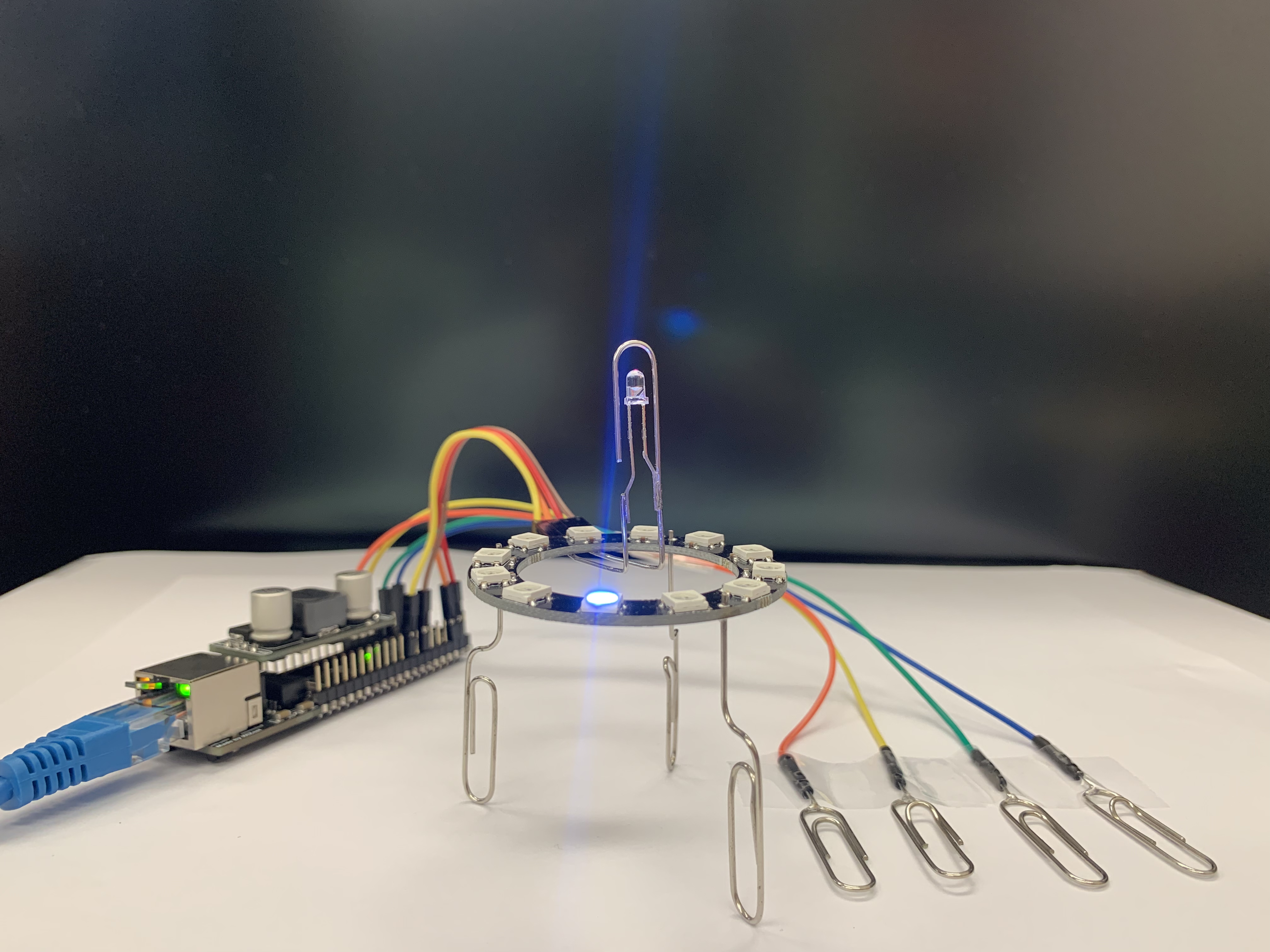
There are 4 pins on the back, they are:
1, WS2812 control pin
2. Power 5V
3.GND
4. Infrared transmitter control pin
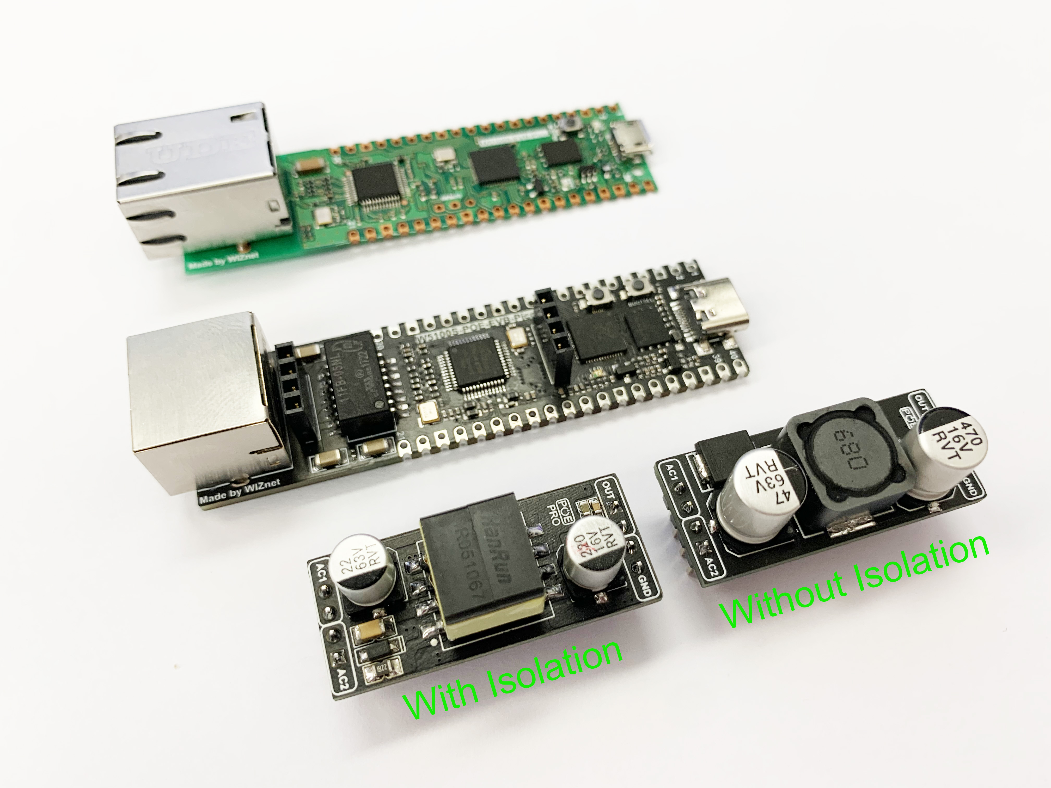
The main control board I use is W5100S_POE_EVB_PICO, which can be understood as W5100S_EVB_PICO with POE function. The external Pin of both is fully compatible, except that the original Micro USB interface is changed to a Type C interface.
I welded the paper clip onto the cable and used it as a touch button. Four touch buttons were used in this project.

The operation logic is as follows:
Button 1(Orange cable), click to select the device, long-press to turn on or turn off the selected device;
Button 2(Yellow cable), add(+) function buttons, for example, in fan mode, it increases the air volume, in TV mode, it increases the previous channel; in air conditioning mode, it increases the temperature...
Button 3(Green cable), reduce(-) function button, for example, in fan mode, it is to reduce the air volume, in TV mode, it is to next channel; in air conditioning mode, it is to reduce the temperature...
Button 4(Blue cable), additional function buttons, such as shaking head mode switching in fan mode, mute mode in TV mode; long-press is setting mode;
The following is the code for the button part. At present, I have only added the control of the fan and TV. Other electrical appliances will also be added. I have also planned new functions. For example, long-press button 4 to enter the setting mode, and then automatically learn. New equipment, learn the key value information of infrared remote control, etc.
void Touch_handling()
{
// key handling
for ( int i = 0; i < touch_count; i++) {
touches[i].update();
if ( touches[i].rose() ) {
Serial.print("Button:");
Serial.println(i);
//ws2812fx.setMode((ws2812fx.getMode() + 1) % ws2812fx.getModeCount());
// if(i==0)
// {
time_now = millis();
// }
// else
{
switch (Device_num){
case 0: //Dyson Fan
{
if(i == 1)
{
IrSender.sendPulseDistanceWidth(38, 2150, 800, 700, 1500, 700, 800, 0x6D510, 21, PROTOCOL_IS_LSB_FIRST, 0, 0);
}
else if (i == 2)
{
IrSender.sendPulseDistanceWidth(38, 2200, 750, 700, 1500, 700, 750, 0xA3510, 21, PROTOCOL_IS_LSB_FIRST, 0, 0);
}
else if(i == 3)
{
IrSender.sendPulseDistanceWidth(38, 2200, 750, 700, 1500, 700, 800, 0x1E9910, 21, PROTOCOL_IS_LSB_FIRST, 0, 0);
}
}
break;
case 1: //SONY TV
{
if(i == 1)
{
IrSender.sendSony(0x1, 0x74, 2, 12);/*电视向上*/
}
else if (i == 2)
{
IrSender.sendSony(0x1, 0x75, 2, 12);/*电视向上*/
}
else if(i == 3)
{
IrSender.sendSony(0x1, 0x14, 2, 12);/*电视静音*/
}
}
break;
case 11:
{
if(i == 1)
{
}
else if (i ==2)
{
}
else if(i ==3)
{
}
}
break;
}
}
}
if ( touches[i].fell() ) {
Serial.printf("Release:");
Serial.println(i);
if(i == 0)
{
if((millis()-time_now)>1000)
{
Serial.print("Turn on/off Device:");
Serial.println(Device_num);
switch (Device_num){
case 0:
{
IrSender.sendPulseDistanceWidth(38, 2200, 750, 700, 1500, 700, 750, 0x90110, 21, PROTOCOL_IS_LSB_FIRST, 0, 0);
}
break;
case 1:
{
IrSender.sendSony(0x1, 0x15, 2, 12);/*电视开关*/
}
break;
}
}
else
{
ws2812fx.setPixelColor(Device_num, BLACK);
if(Device_num <11)
{
Device_num ++;
}else
{
Device_num = 0;
}
ws2812fx.setPixelColor(Device_num, Color_Device[Device_num]);
ws2812fx.show();
}
}
if(i == 3)
{
if((millis()-time_now)>1000)
{
Serial.print("LEARNING MODE:");
Serial.println(Device_num);
switch (Device_num){
case 0:
{
}
break;
case 1:
{
}
break;
}
}
else
{
}
}
}
}
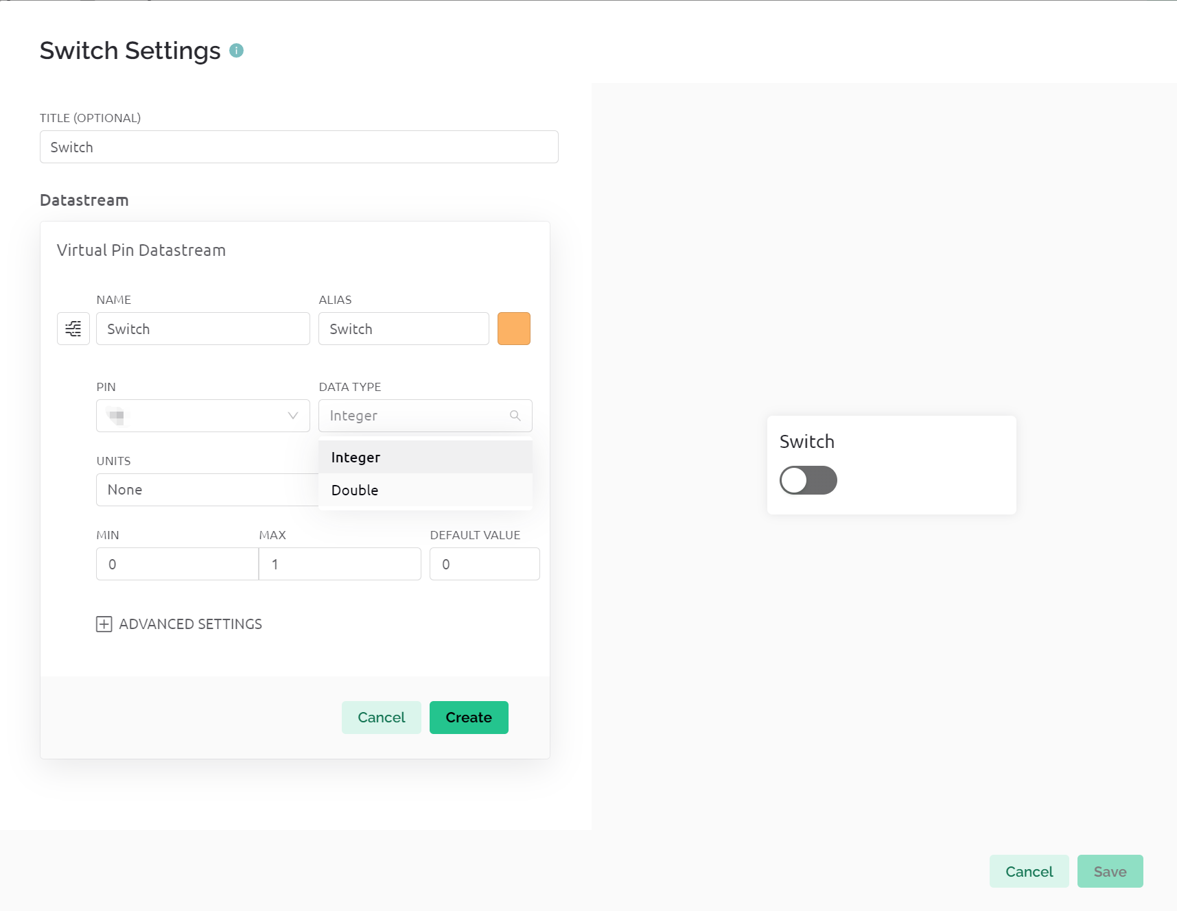
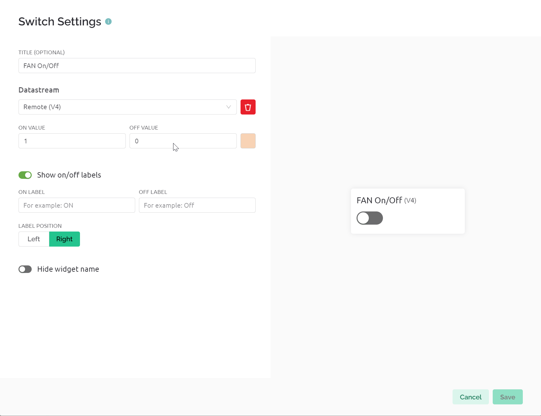
}I implemented the network communication function through BLYNK's Cloud. I created a new virtual pin named V4 and synchronized status information through BLYNK. Because of the free account, I can only create limited new devices, so I used The method is that all controlled infrared devices use the same field to synchronize remote control information, and select the DATA TYPE of Integer; each device occupies a 5-length value to synchronize remote control information. For example, my fan uses 0~4.
State 0: fan shuts down;
State 1: Fan is on;
State 2: Air volume increases;
State 3: Air volume decreases;
State 4: Switching of shaking head mode;
This is the set button state:
This is the code for the fan control part.
BLYNK_WRITE(V4) {
  V_Value= param[0].asInt();
  Serial.print("V4:");
  Serial.println(V_Value);
  if(V_Value == 0)
  {
    IrSender.sendPulseDistanceWidth(38, 2150, 800, 700, 1500, 700, 750, 0x90110, 21, PROTOCOL_IS_LSB_FIRST, 0, 0);
  }
  else if(V_Value == 2)
  {
    IrSender.sendPulseDistanceWidth(38, 2150, 800, 700, 1500, 700, 800, 0x6D510, 21, PROTOCOL_IS_LSB_FIRST, 0, 0);
  }
  else if(V_Value == 3)
  {
    IrSender.sendPulseDistanceWidth(38, 2200, 750, 700, 1500, 700, 750, 0xA3510, 21, PROTOCOL_IS_LSB_FIRST, 0, 0);
  }
  else if(V_Value == 4)
  {
    IrSender.sendPulseDistanceWidth(38, 2200, 750, 700, 1500, 700, 800, 0xE9910, 21, PROTOCOL_IS_LSB_FIRST, 0, 0);
  }
}
In order to know which device is currently selected, I used a WS2812 light ring which with 12 lamp beads on it.
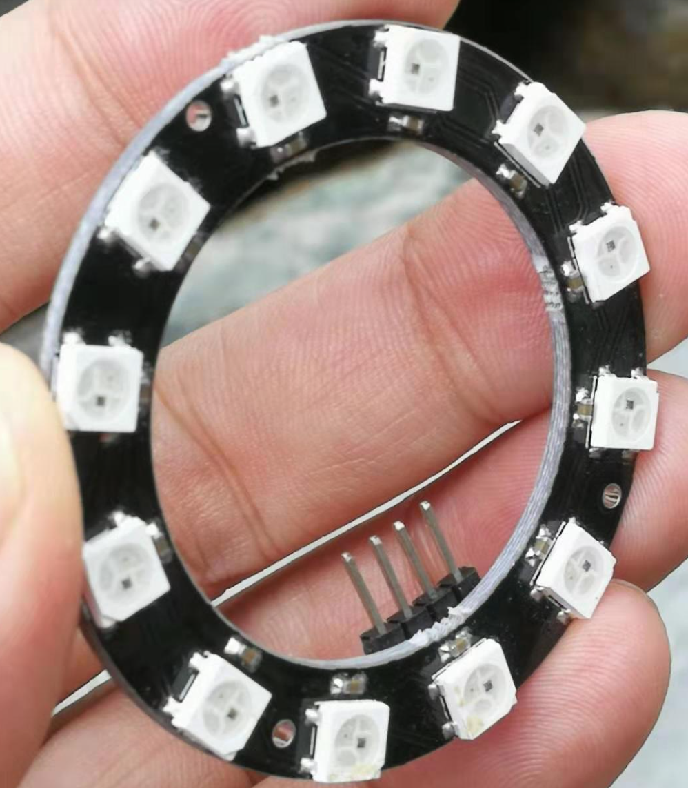
I defined a color for each device to distinguish the device. code show as below:
uint32_t Color_Device[12] = {
  0xFF0000,  // RED
  0x00FF00,  // GREEN
  0x0000FF,  // BLUE
  0xFFFFFF,  // WHITE
  0xFFFF00,  // YELLOW
  0x00FFFF,  // CYAN
  0xFF00FF,  // MAGENTA
  0x33E6CC,   //TYRQUOISE BLUE
  0x800080,  // PURPLE
  0xFFA500,  // ORANGE
  0xFFC0CB,  // PINK
  0xFF8C00   // DARK ORANGE
};
12 lights correspond to 12 devices, such as:
Light 1: Fan
Light 2: TV
Light 3: Air conditioner
Light 4: Ventilation fan
Light 5: apple tv
Light 6: Set-top box
……
BLYNK provides a Device HTTPS API to set or synchronize device information through HTTPS GET. This is why I can control infrared devices through Apple's Siri.
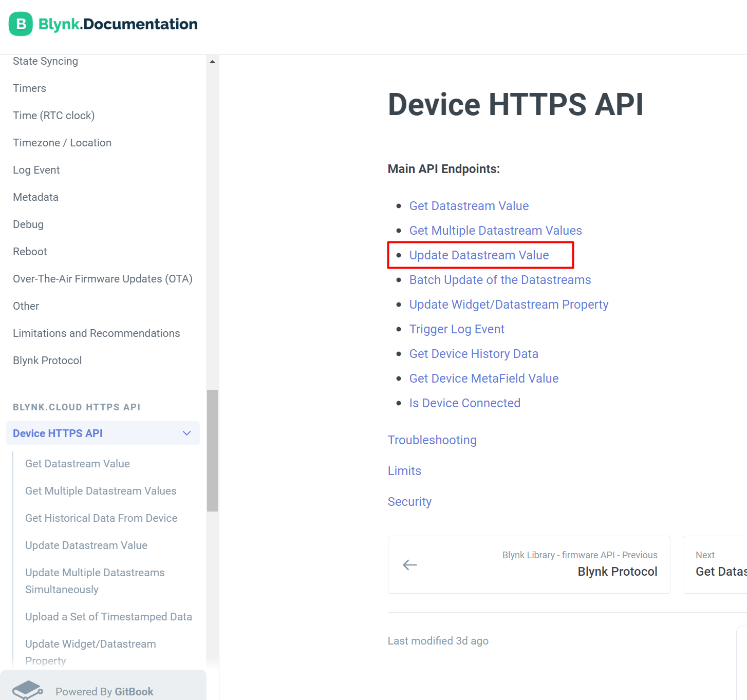
Control signals can be sent to the terminal device through the following format:
https://{server_address}/external/api/update?token={token}&{pin}={value}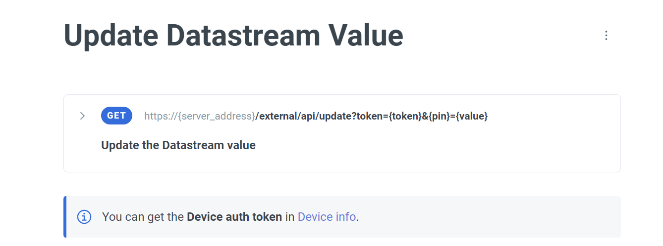
Then add the command in Apple's shortcut command in the "Get URL Content" method. The name of the command is the command required by "Hey Siri".

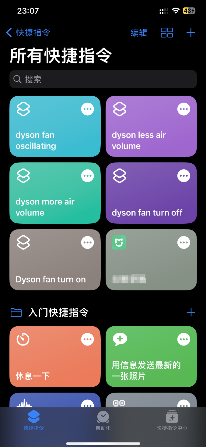
After adding it, you can control the device through "Hey Siri" and shortcut commands.
For example, the shortcut command I added can be used like this:
"Hey Siri, dyson fan oscillating"
"Hey Siri, dyson more air volume"
"Hey Siri, dyson fan turn on"
"Hey Siri, dyson less air volume"
"Hey Siri, dyson fan turn off"
DONE!
-
Remote-Control-Tower-arduino-code
