W5500 board - FDX Led steady on - sending data, not receiving
Ethernet Chips
No replies yet. Be the first to reply.
Join the discussion.
Ethernet Chips
No replies yet. Be the first to reply.
Join the discussion.
Share projects and connect with makers.
Joined before the site update? first.
New to WIZnet Makers?
We sent a verification link to your address. Open it to activate your account, then log in.
Accounts from this email provider are reviewed by an administrator after verification. Approval usually takes one business day.
Already have an account?
Enter your email address. If it belongs to an account, we'll send a link to set a new password. Members who joined before the site update use this to set their password.
If an account uses that address, we sent a link to set a new password. The link works once and expires in 30 minutes.
Know your password?
Need an account?
RE: W5500 board - FDX Led steady on - sending data, not receiving
by Edward ·
Hi.
I think… Don’t care.
important point is LINK led.
because, LINK is PHY(hardware) link indicate LED.
ACT(FDX) is data TX/RX indicate LED.
Thank you
RE: W5500 board - FDX Led steady on - sending data, not receiving
by MexxMe ·
Hi,
Communication doesn’t work, that is the issue
I am not concerned about led at all…
RE: W5500 board - FDX Led steady on - sending data, not receiving
by Eugeny ·
Which MAC address is used for the W5500 chip?
RE: W5500 board - FDX Led steady on - sending data, not receiving
by MexxMe ·
HI,
I’ve been using address range from WizNet chips configured in Atmega328 chip- 00:08:DC:xx:xx:xx
I am assigning that address from Arduino code
I dont know how to read actual MAC address of W5500 chip
Still dont think that issue is with Atmega/Arduino side since W5500 behaves the same even with Atmega removed from board
RE: W5500 board - FDX Led steady on - sending data, not receiving
by MexxMe ·
I found mistake in my design but it does not solve my problem
Can some of experienced guys help here?
Still don’t understand how previous design worked…
Pinout of Bel Fuse RJ45 connector states that pins 1&2 are TX
I have connected it to pins 5&6 of W5500, which is actually receive.
It means that I have two capacitors 6,8nF on TX line, connector pins 1&2
But I have removed RJ45 connector and connected it with wires in proper way, still same behavior
going crazy…
RE: W5500 board - FDX Led steady on - sending data, not receiving
by Edward ·
I don’t find schematic mistaken part.
Are you making PCB ?
If you making PCB, You need checking artwork.
refer to below 2 schematic & Artwork file.
wizwiki.net/wiki/doku.php?id=pro … 50sr_ds_kr
wizwiki.net/wiki/doku.php?id=osh … uino:start
Thank you
RE: W5500 board - FDX Led steady on - sending data, not receiving
by MexxMe ·
Thanks for advice
I did designed board myself so this could be a reason why it is not working.
Now I am making new design so your opinions are welcome
I have routed RX and TX lines to W5500, keeping in mind distance from power lines and each other
Total length of the traces is almost the same (0,5mm difference)
Any comments to it?
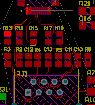
Thank you in advance
RE: W5500 board - FDX Led steady on - sending data, not receiving
by Edward ·
Hi.
Are you using RJ-45 inside transformer ?
If using RJ-45 inside transformer, It is not pave cooper in pin environs.
And you need more wide gnd line on ethernet environs pin.
Thank you