W5500 LinkLED/AcktLED behaviour
Ethernet Chips
No replies yet. Be the first to reply.
Join the discussion.
Ethernet Chips
No replies yet. Be the first to reply.
Join the discussion.
Share projects and connect with makers.
Joined before the site update? first.
New to WIZnet Makers?
We sent a verification link to your address. Open it to activate your account, then log in.
Accounts from this email provider are reviewed by an administrator after verification. Approval usually takes one business day.
Already have an account?
Enter your email address. If it belongs to an account, we'll send a link to set a new password. Members who joined before the site update use this to set their password.
If an account uses that address, we sent a link to set a new password. The link works once and expires in 30 minutes.
Know your password?
Need an account?
RE: W5500 LinkLED/AcktLED behaviour
by Coccoliso ·
hi, and if you have a free i/o can turn on your own LED as you please.
you can find the description of the LEDs on page 10 of the datasheet.
You’re going to check the status of the network through the state of the LEDs?
If so maybe you should read the correct register: PHYCFGR (W5500 PHY Configuration Register) [R/W] [0x002E] [0b10111XXX]
(page 43 of datasheet) that has DPX bit for duplex status, SPD bit for the speed status and LNK bit for the link status and do not blink
RE: W5500 LinkLED/AcktLED behaviour
by Salieri ·
Hi. Thanks for the help.
The thing is, I don’t really think that the LED’s are the problem as much as they’re probably the symptom of a larger issue with which I hoped someone here would be familiar with.
After the initialization the contents of the PHYCFGR are 0b10111010 which seems to indicate HalfDuplex, 100 Mbps and Link down.
I’m guessing this means that the W5500 tries to establish a link but doesn’t seem to be able too? I’m guessing that the period where the LED’s are ON is the period where the W5500 tries to establish the link.
Would that be a correct assesment?
I’m really pulling my hair here. It feels like I’m missing something really crucial in the initialization procedure but I can’t figure out exactly what. If there’s a problem with the PCB layout, then I’m seriously screwed.
This is the raw init routine code. Am I doing anything exceedingly stupid?
The parameters for w5500_SendCommand are (in order):
[code] // Reset W5500
one_data[0] = 0x80;
w5500_SendCommand(MODE, CMN, WRITE, one_data, 1);
RE: W5500 LinkLED/AcktLED behaviour
by Coccoliso ·
Hi, .
.
from what I remember once you’ve set the main parameters (IP,MAC,GW and SUBNET) and buffers the device responds to the ping without having to do anything else ( your PHYCFGR is taken from PMODE[2:0] PINs = All capable, Auto-negotiation enabled ).
My init sequence in any use I make it is always the same: 4 parameters and buffers, when using DHCP set all the parameters to 0 except for the MAC address and then set them with the data info returned from the server.
Your initialization sequence seems correct … only I set the buffer immediately after essential common parameters like gateway, MAC, subnet and IP and before using any socket register but there should be no problems
Are you sure you read the registers properly? You tried to read for example the word at 0x0039 (VERSIONR) that should be 0x55 0x00?
RE: W5500 LinkLED/AcktLED behaviour
by Salieri ·
Hi!
It works!
Thank you for your help. The problem turned out not to be in the initialization routine, but in the physical layout. I’ve desoldered a couple of resistors which were there experimentally, and the damn thing came alive. Definitely taught me not to eyeball damping resistors.
Again, thank you for your willingness to step up.
RE: RE: W5500 LinkLED/AcktLED behaviour
by seands ·
Hi Salieri, I’m having the same symptoms. Would you mind elaborating on what your problem was? Were the “experimental” resistors damping resistors in series with the TX and/or RX lines? Or pull-up/pull-down resistors? Did you end up using any of these in your working design?
RE: W5500 LinkLED/AcktLED behaviour
by Salieri ·
Hi!
Yeah, I was talking about the series resistors in line with Rx/Tx. I took them out and short-circuited the connection, and it worked. I wound up throwing them out of the final design since I had the W5500 fairly close to the jack so there wasn’t much added inductance or capacitance to dampen.
I kept the pull ups as per the reference design.
RE: W5500 LinkLED/AcktLED behaviour
by seands ·
Great - I’ll try that. Looking back, the reference schematic I used actually defies these as 0R, but in the EMI reduction text panel suggest experimenting with non-0R values. I put in 33R as per their experiments, but in hindsight I should have started with 0R and worked up…
Thanks!
RE: W5500 LinkLED/AcktLED behaviour
by instalator ·
I do not use resistors on TX / RX and I have such a problem.
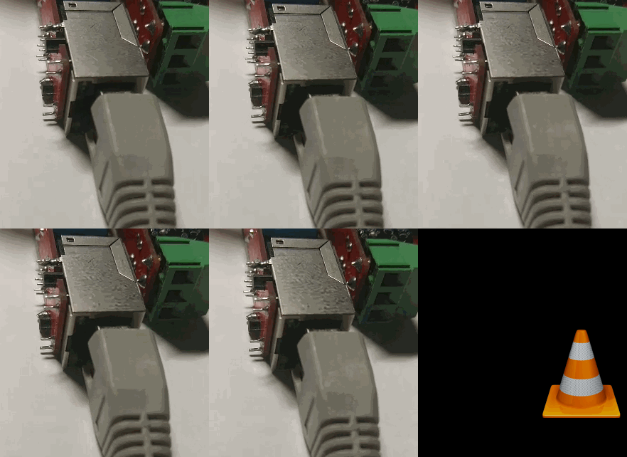
If you turn it off and on several times, it starts working well.
RE: RE: W5500 LinkLED/AcktLED behaviour
by Eugeny ·
W5500 can not catch carrier properly, and resets its PHY in loop.
Share your circuit diagram and board layout.
This behavior can be caused by another device you connect another end of the cable to (e.g. switch/hub). Try another hub to see if there will be any difference.
RE: W5500 LinkLED/AcktLED behaviour
by instalator ·
I use different builds and get the same effect. This does not always happen, and only when power is applied.
PMODE2, PMODE1, PMODE0 all Pull-up.
RE: W5500 LinkLED/AcktLED behaviour
by W5500Newbie ·
I have same problem with w5500 mini ethernet module There are some resistor in series with 1,2 and 5,6. pin which are 50 ohm. I removed them but leds never turn on.
As instalator said, sometimes works sometimes when power is applied led sequence starts never connect anymore
RE: W5500 LinkLED/AcktLED behaviour
by RusikOk ·
you need to apply a low level to the RESET chip and re-initialize it