
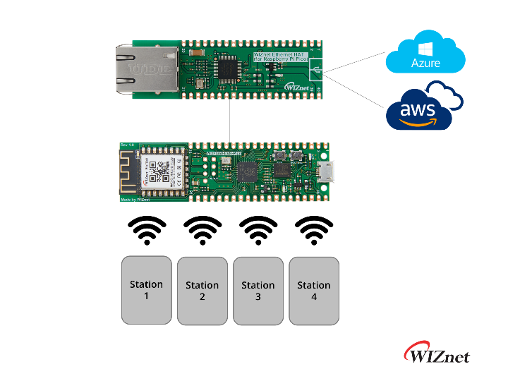
W5500-EVB-Pico and WizFi360 Azure IoT Gateway
The process of connecting W5500-EVB-Pico to Azure IoT Hub by MQTT using C/C++ and Wi-Fi Gateway for sending and receiving messages.
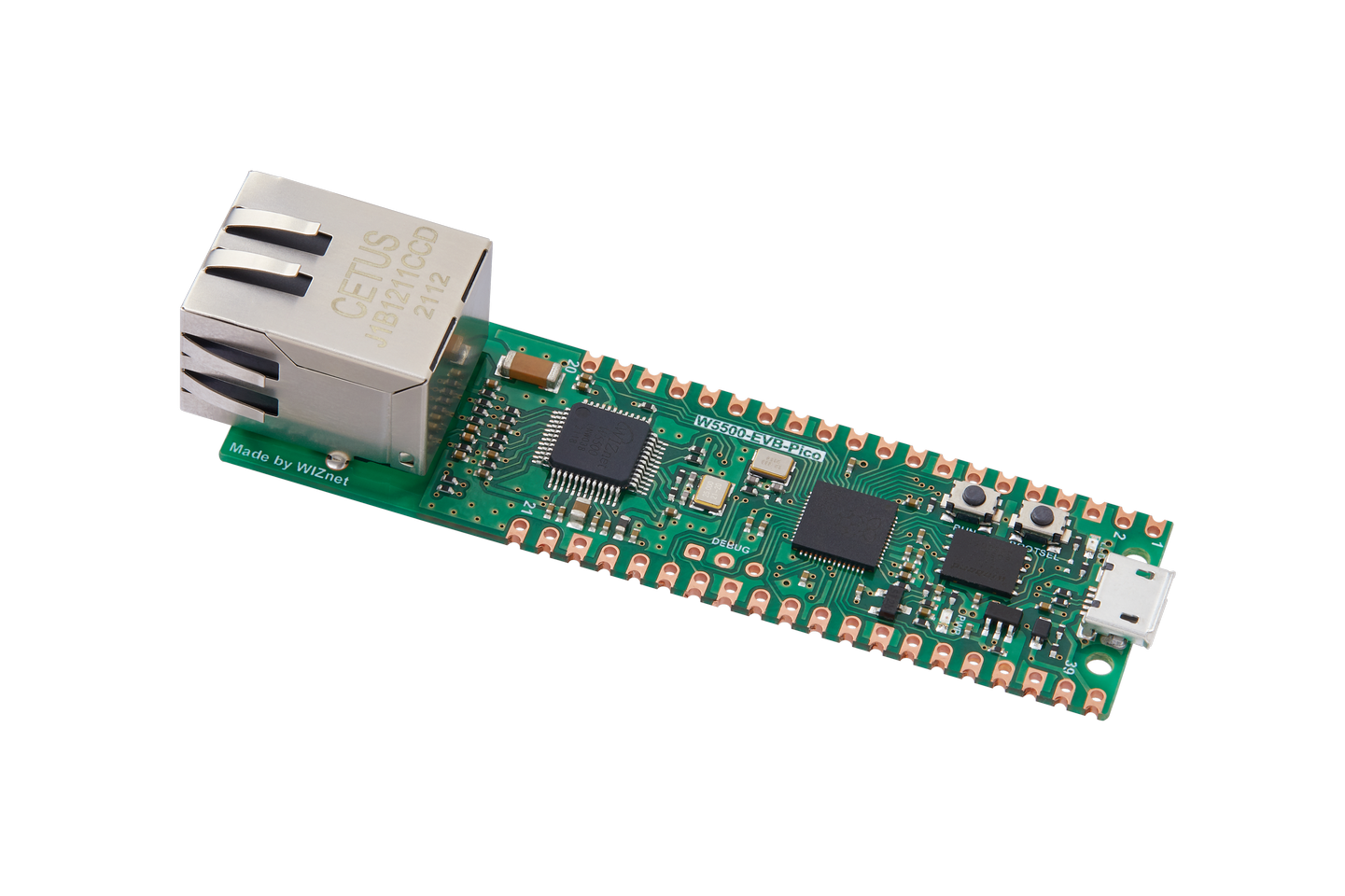
WIZnet - W5500-EVB-Pico
x 1
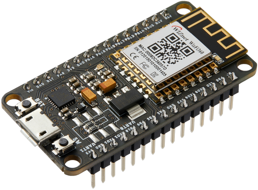
WIZnet - WizFi360-EVB-Mini
x 1
Microsoft - Azure IoT Explorer
x 1
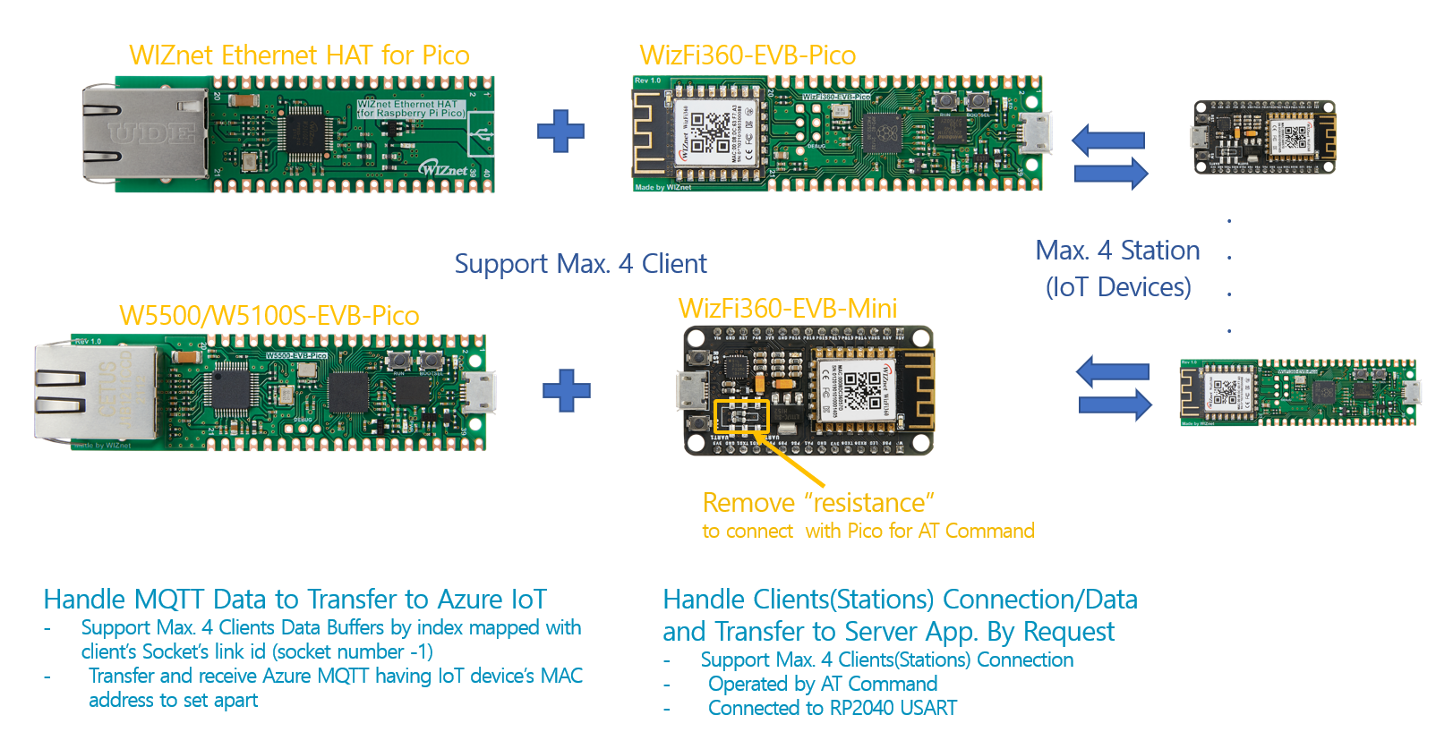
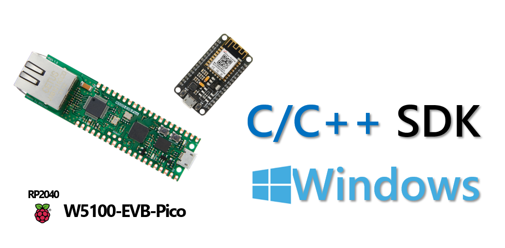
The process of connecting W5500/W5100S-EVB-Pico to Azure IoT Hub by MQTT using C/C++ and Gateway for sending and receiving messages.
You can also construct the below HW types by using W5500/W5100S or Ethernet HAT+WizFi360-EVB-Pico.
I used a SAS Token authentication method for IoT Hub.
Components
1. H/W
- W5100S-EVB-Pico for Ethernet an MCU
- WizFi360 for Wi-Fi
- Micro 5pin USB cable
- LAN cable
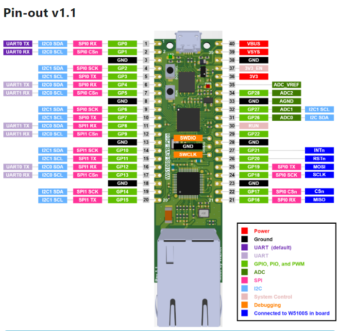
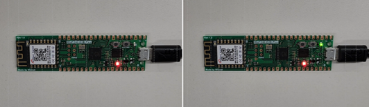
Details on W5500 and WizFi360 PIN Connection
TDX and RDX jumpers from the WizFi to send UART data to the UART W5500-EVB-Pico pins.
1. 1 WizFi360 Pin Map

1. 2 W5500-EVB-Pico Pin Map
https://docs.wiznet.io/Product/iEthernet/W5100S/w5100s-evb-pico
2. S/W
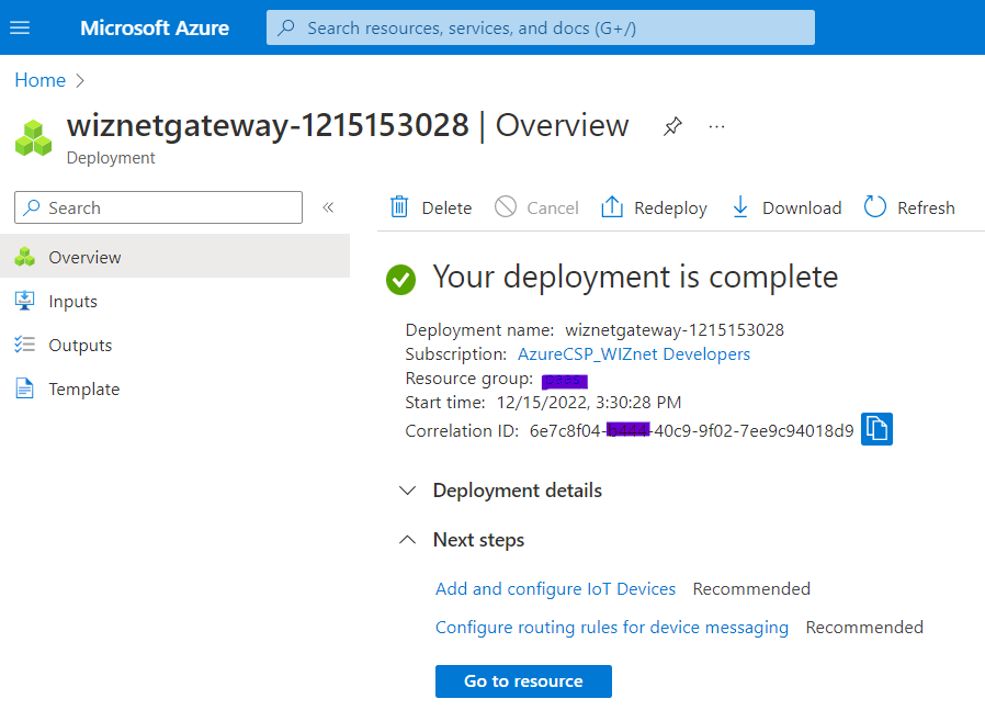
2.1 Prepare Azure Resource
Create an Azure IoT Hub
There are various ways to create an Azure IoT Hub, such as the Azure portal, Azure CLI, REST API, etc. In the beginning, we mainly use the method of creating through the Azure portal.
Instructions can be found at the link below.
How to Generate and Register Cert.
Follow this guide: https://www.hackster.io/lawrence-wiznet-io/azure-iot-cloud-monitored-and-controlled-raspberry-pi-pico-65fc93
2.2 RP2040 C/C++ Development Environment
2.3 C/C++ Firmware
2.3.1 Build
The build operation used Raspberry Pi C/C++ environment.
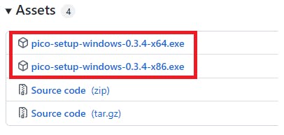
Download and Install Programs for the integrated Development Environment
Release v0.3.4 · ndabas/pico-setup-windows · GitHub
2.3.2 Repository clone
Raspberry Pi Pico W5x00 Azure IoT SDK Examples
RP2040 - W5100S or W5500 network examples - Azure IoT Cloud functions, Azure IoT SDK, Azure IoT device client, and server.
- 'iothub_ll_telemetry_sample' application result
- iothub_ll_c2d_sample' application result
- iothub_ll_client_x509_sample' application result
- prov_dev_client_ll_sample' application result
Build W5100S-EVB-Pico Device Firmware
Device Source code
I uploaded the RP2040 (W5500/W5100 and WizFi360) Gateway device code to the link below to control through the WiFi IoT device's MAC address.
The Azure IoT Hub Gateway contents have been added and modified from the RP2040-HAT-AZURE-C: original example code.
- W5100S/W5500 Azure IoT Hub Connection Settings
- Modification of telemetry message transmission to / receiving from IoT Devices through MAC address
Clone the Repository including the submodules and retrieve the submodules.
git clone https://github.com/Wiznet/RP2040-HAT-AZURE-C.git
cd RP2040-HAT-AZURE-C

git submodule update --init- How to Manage the Device Information for this Gateway
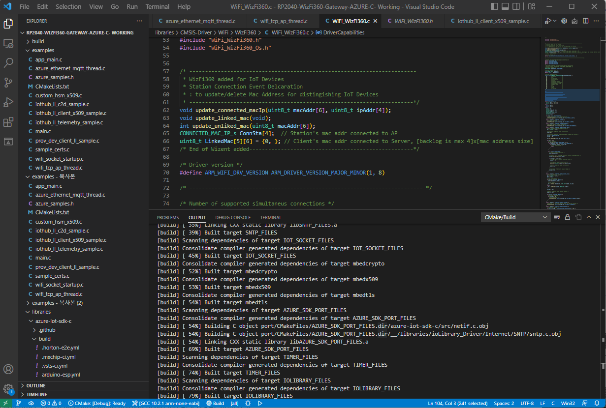
This gateway executes the ethernet thread and Wi-Fi server thread. When a client is physically connected to AP, we call it a connected state. It adopted in Wi-Fi driver; I modified CMSIS WiFi driver WiFi_WizFi360.h and WiFi_WizFi360.c to manage connection information. (For this project, I updated the client's MAC address managing from this project: https://www.hackster.io/bonchanggoo/iot-gateway-w5500-raspberry-pi-pico-wizfi360-f79fc0)
typedef struct {
  uint8_t conn_mac[8];
  uint8_t conn_ip[4];
} CONNECTED_MAC_IP_s;
When a client is logically connected to AP's server, we called link connected. So gateway manages two separate clients' IP and MAC address data. The gateway sends and receives each IoT device's data between the Azure IoT hub and IoT devices by distinguishing the IoT device's MAC address. We called it a linked MAC address.
/* ------------------------------------------------------------------------
 * WizFi360 added for IoT Devices
 * Station Connection Event Declaration
  : to update/delete Mac Address for distinguishing IoT Devices
 * -----------------------------------------------------------------------*/
void update_connected_macIp(uint8_t macAddr[6], uint8_t ipAddr[4]);
void update_linked_mac(void);
int update_unliked_mac(uint8_t macAddr[6]);
CONNECTED_MAC_IP_s ConnSta[4];   // Station's mac address connected to AP
uint8_t LinkedMac[5][6] = {0, }; // Client's mac address connected to Server- Set your board network information and select a sample application
In the following RP2040-HAT-AZURE-C/examples/main.c source file, find the line similar to this and replace it as you want:
(...)

// The application you wish to use should be uncommented
//
#define APP_TELEMETRY
//#define APP_C2D
//#define APP_CLI_X509
//#define APP_PROV_X509

// The application you wish to use DHCP mode should be uncommented
#define _DHCP
static wiz_NetInfo g_net_info =
    {
        .mac = {0x00, 0x08, 0xDC, 0x12, 0x34, 0x56}, // MAC address
        .ip = {192, 168, 11, 2},                     // IP address
        .sn = {255, 255, 255, 0},                    // Subnet Mask
        .gw = {192, 168, 11, 1},                     // Gateway
        .dns = {8, 8, 8, 8},                         // DNS server
#ifdef _DHCP
        .dhcp = NETINFO_DHCP // DHCP enable/disable
#else
        // this example uses static IP
        .dhcp = NETINFO_STATIC
#endif
};- Set the key information
Copy & Paste the proper connection string and key value from the Azure Portal to RP2040-HAT-AZURE-C/examples/sample_certs.c:
/* Paste in your IoT hub connection string  */
const char pico_az_connectionString[] = "[device connection string]";

const char pico_az_x509connectionString[] = "[device connection string]";

const char pico_az_x509certificate[] =
"-----BEGIN CERTIFICATE-----""\n"
"-----END CERTIFICATE-----";

const char pico_az_x509privatekey[] =
"-----BEGIN PRIVATE KEY-----""\n"
"-----END PRIVATE KEY-----";

const char pico_az_id_scope[] = "[ID Scope]";

const char pico_az_COMMON_NAME[] = "[custom-hsm-device]";

const char pico_az_CERTIFICATE[] =
"-----BEGIN CERTIFICATE-----""\n"
"-----END CERTIFICATE-----";

const char pico_az_PRIVATE_KEY[] =
"-----BEGIN PRIVATE KEY-----""\n"
"-----END PRIVATE KEY-----";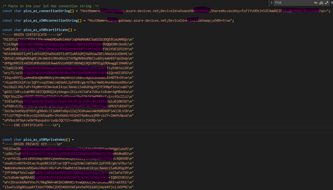
2.4 Build and Run
1. Build and Run the application
Run VS Code or Developer command prompt for VS 2019 and build the application. copy main.uf2 file into Raspberry Pi Pico board.
2.5 Firmware Upload
Upload the firmware to the device.
Enter Boot Mode
If you press the RUN button while holding down the BOOTSEL button, it enters the boot mode and there is no need to re-apply the power.
3. Setup Azure IoT hub
Install Tools and libraries
There are several ways to get information, and among them, I used IoT Explorer.
Install the PC library in the Azure environment.

Get device information from IoT Explorer
You need to get the information to connect to Azure IoT Hub and write it in your code.
See the Azure IoT Hub Guide: Communicate with your IoT hub using the MQTT protocol for what each field requires when communicating with MQTT
In the case of the example code, the data below should be obtained.
- Device Connection String
- Device SAS Token
If you look at the code, it is implemented to parse the Connection String to obtain the Hostname, Device Id, and Shared access key values.
Set up IoT Explorer IoT Hub connection
- Reference: https://docs.microsoft.com/en-us/azure/iot-fundamentals/howto-use-iot-explorer#connect-to-your-hub
First, need to grant access so that IoT Explorer can access IoT Hub.
Among the default permissions, iothubowner permission including all permissions will be granted to IoT Explorer.
Click iothubonwer, click the button to the right of the Primary connection string, copy the value, and then paste it into the window that appears when you click Add connection in IoT Explorer and save.
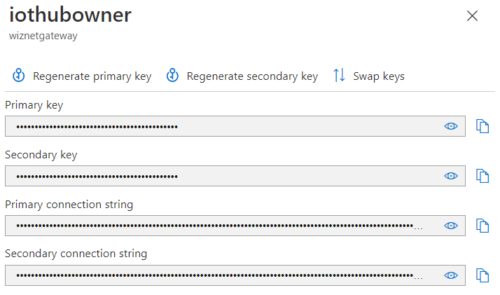
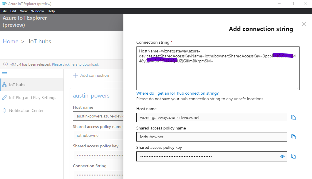
If you set up this setting only once in the beginning, you can perform most of the tasks for IoT Hub and devices in the tool.
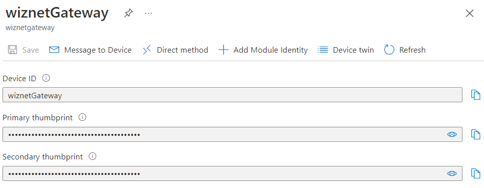
After creating the device, get the information value as shown in the figure.
4. Execution and monitoring
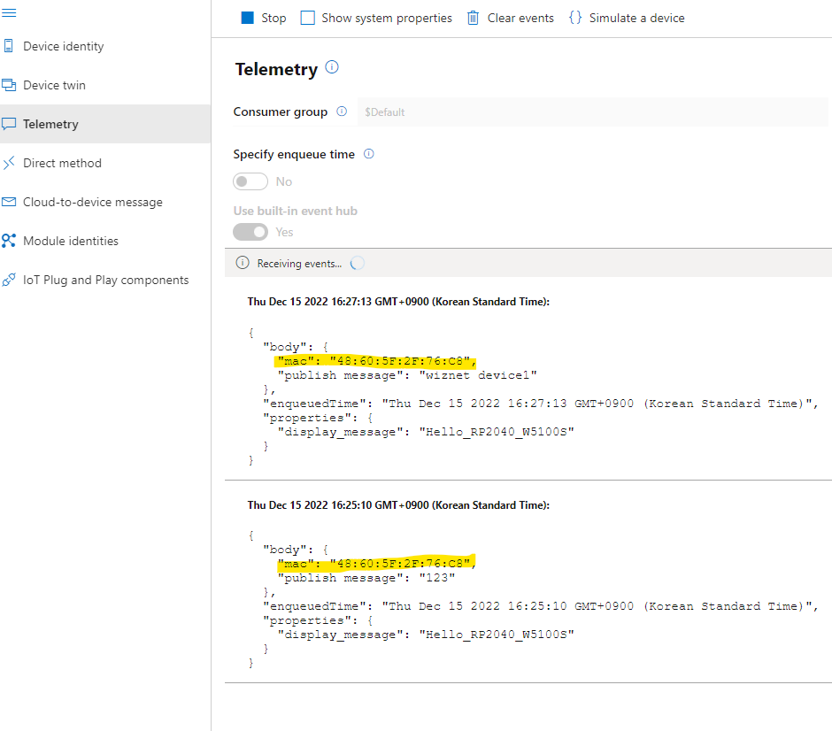
Simple Telemetry Test: Recieve the Messages from the IoT Device with the Device's own MAC address
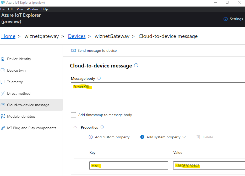
Cloud-to-Device message: Send the Messages to the IoT Device with the Device's own MAC address
IoT Device's Received Message Log
Sending message 1 to IoTHub
Message:
iotSocketRecv data is 123
Sending message 7 to IoTHub
Message:
-> 08:18:48 PUBLISH | IS_DUP: false | RETAIN: 0 | QOS: DELIVER_AT_LEAST_ONCE | TOPIC_NAME: devices/wiznetGateway/messages/events/display_message=Hello_RP2040_W5100S&%24.cid=CORE_ID&%24.mid=MSG_ID&%24.ct=application%252fjson&%24.ce=utf-8 | PACKET_ID: 9 | PAYLOAD_LEN: 53
<- 08:18:50 PUBACK | PACKET_ID: 9
Confirmation callback received for message 7 with result IOTHUB_CLIENT_CONFIRMATION_OK
iotSocketRecv data is wiznet device1
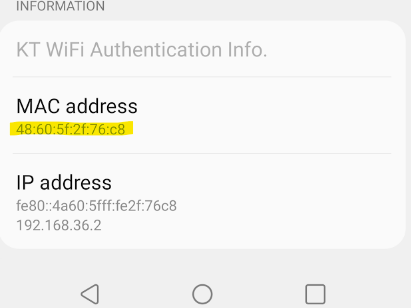
<- 07:42:36 PUBLISH | IS_DUP: false | RETAIN: 0 | QOS: DELIVER_AT_LEAST_ONCE | TOPIC_NAME: devices/wiznetGateway/messages/devicebound/%24.mid=080d3e1f-e25e-437e-b15b-5525878f9439&%24.to=%2Fdevices%2FwiznetGateway%2Fmessages%2Fdevicebound&mac=48%3A60%3A5F%3A2F%3A76%3AC8 | PACKET_ID: 5 | PAYLOAD_LEN: 9
Received Binary message
Message ID: 080d3e1f-e25e-437e-b15b-5525878f9439
Correlation ID: <unavailable>
Data: <<<Power Off>>> & Size=9
Message Properties:
Key: mac Value: 48:60:5F:2F:76:C8
macstr: 48:60:5F:2F:76:C85h en = 26
Received C-to-D Message: Power Off
MQTT Subsribed the msg to client: Power Off, idx = 1
Message Call Count is 4:
-> 07:42:37 PUBACK | PACKET_ID: 5
iotSocketSend data is Power Off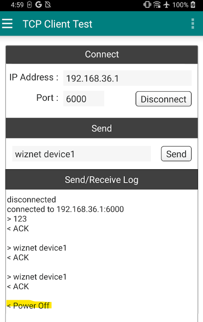
How to consist the Remote IoT Device
You can set it up so that Azure IoT Hub can control IoT Devices (Client) through this Gateway refer to the below.
TCP Client LED ON / OFF Reference and Example:
https://maker.wiznet.io/eric_g/projects/tcp-client-led-on-off-for-raspberry-pi-pico-with-wizfi360-1/
-
AzureGateWay
code and cmake file
