Wiznet makers

alistair

Published July 07, 2024 © MIT license (MIT)

0 UCC

0 VAR

3 Contests

0 Followers

0 Following

WIZnet - Live Train

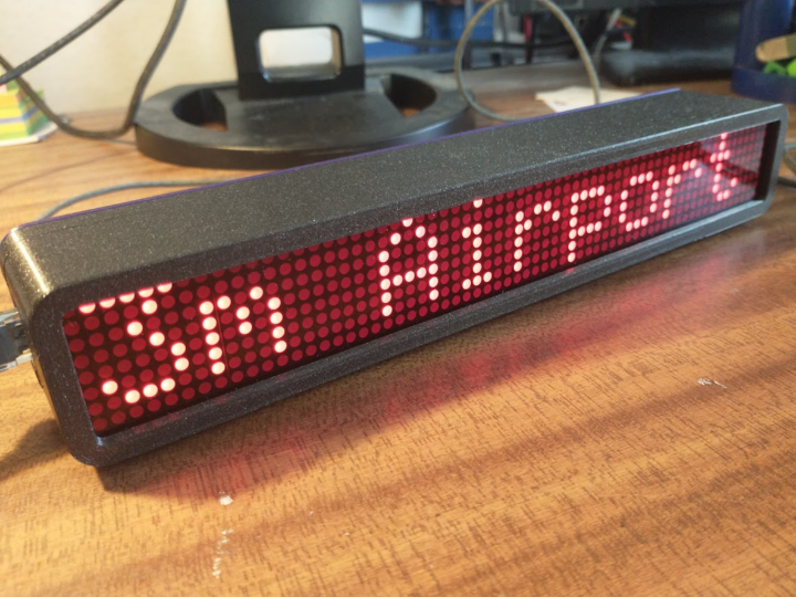
A device will display live information for a local train station. It will show departures, and and disruptions.

COMPONENTS Hardware components

WIZnet - W7500

x 1

A WIZnet Surf 5 with a WIZPoE-P1 module.


Arduino - Arduino Pro Mini

x 1


x 1

Software Apps and online services

microsoft - VS Code

x 1


PROJECT DESCRIPTION

This project is to create a small matrix display that will show train departure time in my lab. This is so we know when is a good time to leave for the train, and when the trains are delayed so I can stay in the warm and dry.

Building the Display

The display uses two common matrix moduled that are based around the MAX7219 LED driver.

These drivers are driven by a controller based on an Arduino Pro Mini. Any information received through the Arduino serial and interfaces is stored and used to instruct the MAX7219 drivers using the SPI interface.

The hardware is simple and can be soldered up without any extra components.

To write the firmware to the Arduino Pro Mini simply use Arduino IDE library manager to download the “LEDMatrixDriver” library and compile the code linked to from this page. There is no configuration required, however you may want to change the default message.

Finally the display models can be attached to the frame. Remember to leave the large hole to the side you want the network socket to be.

Building the Network Interface

The power and communication is done using the WIZnet Surf 5 with a WIZPoP-P1 module attached.

First solder the header pins for the WIZPoP-P1 module into the WIZnet Surf 5, and then attach the required cables as photographed.

I recommend adding a connector to connect to the display driver to allow that driver’s firmware to be updated in the future. The wire between GPIOA14 (pin 17) is not needed but is included for future development.

To load the firmware fist install the tool chain by following the instructions from. https://maker.wiznet.io/TheoIm/projects/how-to-install-vs-code-for-surf-5/ . After you have this working download the examples from https://github.com/Wiznet/W7500x-Surf5 and then follow the instructions in the tutorial at https://maker.wiznet.io/TheoIm/projects/how-to-make-surf-5-project-in-vs-code/ to check everything is working.

Now you have a working system downloading the firmware files linked from this page to the “Projects” folder in the examples you downloaded earlier and add it to the makefile so it will compile.

The only thing you will need to configure is the server where you will be getting the line information from. This is done by editing the values of dns_domain_name[] and http_request_path[] on lines 51 and 54 respectively.

Assembling the Enclosure

The enclosure is designed to be 3D printed with a laser cut screen. Once you have the parts the WIZnet Surf 5 should slot securely into place.

The display controller is best secured with a double sided sticky pad.

Once this is done the display modules can be inserted, the screen placed on top, and the outer shell of the enclosure slid over the top.

Finally you may want to add some feet so this display sits nicely on a shelf.

Server Software

The display needs to connect to an endpoint to retrieve the live data. The source of this data will change depending on where you are and the transport data you are trying to retrieve. I am using it on the local Metro system and retrieving the (almost) live data through a public API.

I have included a copy of my server code as an example.

For it to work simply add a line to the body of the returned data starting with “###” (three hashes) and the remainder of the line will be displayed.

Demonstration

This is a video of the display showing live information for a local station.

Because of rate limits on the API it is only updating every couple of minutes.

Documents
  • Case (outer part)

    Print inverted with the narrower screen side facing the printer bed. No supports will be required.

  • Case (inner part)

    Print with the open side up. Minimum fill. No supports should be required.

  • Screen Mounting Frame

    Laser cut from 3mm ply or acrylic to mount your screen modules on.

  • Screen Protector

    Laser cut in a clear, or a colour matching your display.

  • Network Module Firmware

    Check the instruction here for writing to the Surf 5 module.

  • Display Firmware

    This can be written to the display controller using the Arduino IDE.

  • Wiring Diagram

    Note that the colours on the diagram do not use the colours in the prototype photographs.

Comments Write