Workshop 88 door lock
Workshop 88 door lock
1
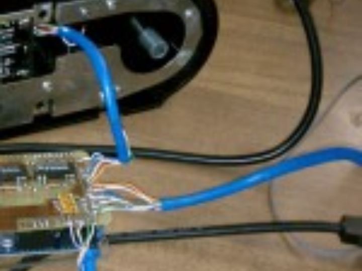
Components
Hardware components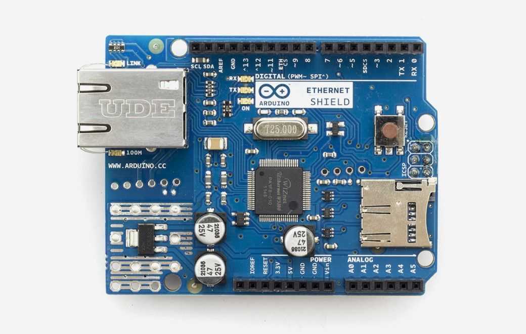
Arduino - Arduino Ethernet Shield
x 1

Project description
As part of upgrading the W88 infrastructure, we’d like better records of who’s in the space and when. The new lock on the W88 front door only allows 2 combinations, and so isn’t very helpful in logging who’s there.
This project hopes to fix that by reverse engineering the connection between the keypad on the outside and the lock mechanism on the inside, intercepting keypresses from the outside, comparing them to a larger list of valid combinations, and if a valid one is entered logging that code and spoofing a valid code into the lock to open the door. Bill and I have made some initial progress.
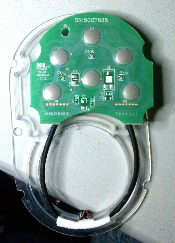 The keypad has 6 buttons and is backlit with 3 red/green LEDs. While there are spots on the keypad PCB for other stuff, nothing else is populated on our board.
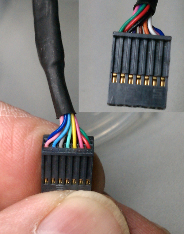 The connection between the pad and the lock is a 14 conductor cable terminated as two 7 conductor pads on the keypad and a 2×7 female header apparently on 0.05″ centers.
 Before we took it apart far enough to see the keypad PCB, we figured that with that many wires, each button was probably brought out as 2 contacts. Using an audible continuity tester in the good multimeter, we guessed what the connector layout might be and tried to find which contacts went to which button. Nada. We had some thin wire that fit nicely into the connector and even took 6 pieces of wire, picked 6 random holes and tried to increase our chances of finding at least something by connecting the continuity checker to them 3 at a time. After a couple more tries that way, still nothing. Concerned that it might use the conductive carbon contact technology in some cheap keypads and the resistance was too high to trigger the audible indicator, we even started looking at the ohmmeter indication rather than listening for the noise – still nothing.
After taking it apart enough to inspect the PCB, we visually traced the 2 connections to each switch and then had no trouble hearing the switch closures. We were just unusually unlucky in the pin choices we blindly made initially.
The good news is that both sides of each switch are in fact brought out to the connector, so sensing which keys are pressed and spoofing presses to the lock shouldn’t be too hard.
Here’s the pinout of the connector, looking into the holes, with the key shown:
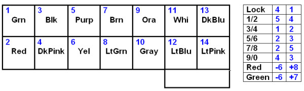
 The pin numbers are numbered pads on the keypad PCB and match the numbers marked on the lock PCB male connector. Keypad switch and LED pin numbers are shown.
No info at all on the single-row female header on the board that’s visible through the battery compartment except that it’s more like 0.08″ centers than 0.1″.
