


Why the W5500 Beat the ENC28J60 and AX11001 in a UCF Animatronic Trade Study
Full hardware TCP/IP stack, eight sockets, a dedicated 32 KB buffer, 80 MHz SPI. UCF Group 21 wrote the comparison down, then measured the chip on its bench.
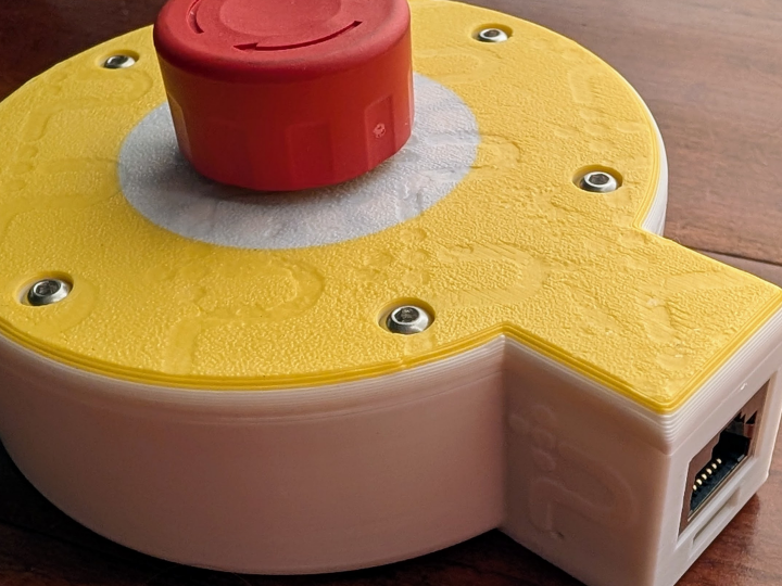

WIZnet - W5500
x 1

Ethernet controller on the custom SAMD21 motor controller PCB, selected over the ASIX AX11001 and Microchip ENC28J60 in the report's Table 3.26 trade study. Circuit adapts the Arduino MKR ETH Shield r
A Dinosaur Run Like a Factory Machine
Group 21 is a four-student senior design team from the University of Central Florida: electrical engineering majors Austin Berg, Melvin Guzman, and Tony Torres, and computer engineering major Armando Diaz, sponsored by Richard Kim of ROBOTIS and mentored by Dr. Lei Wei. Austin Berg, who hosts the project on his portfolio site, lists controls work on Universal Orlando Resort rides and shows and PLC-focused ground support equipment at Blue Origin.
The team's project, Industrial Robotic Animatronic, drives a 3D-printed T-Rex skeleton with the same equipment class that runs factory lines: an Allen-Bradley Micro820 PLC, a touch-panel HMI, and Modbus TCP across one wired Ethernet switch. The project site calls it "an open, customizable alternative to proprietary solutions for entertainment, education, and research applications." On that network sits a custom motor controller board whose Ethernet controller is a WIZnet W5500, selected through a written three-chip trade study.
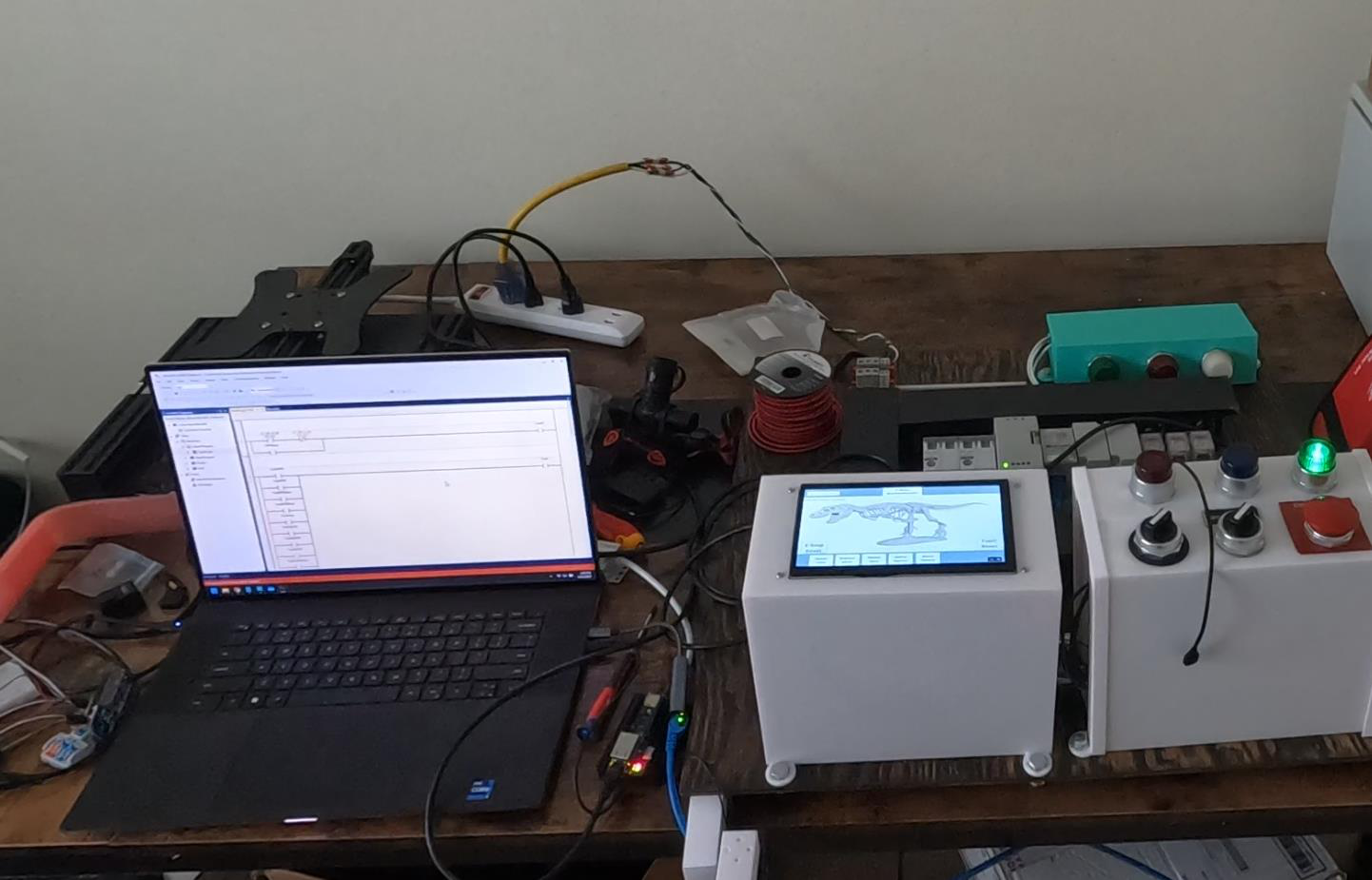
The team published its 132-page Senior Design 2 final report on 07/20/2025, served with an HTTP Last-Modified of July 30, 2025, alongside a Senior Design 1 demo video, a final demo video, and an 8-page conference paper dated 07/07/2025. All sources were re-checked for this article on August 28, 2026.
Why the Team Refused a Wireless Control Panel
Section 3.1.2 weighs three ways to build the operator interface: a web browser application, remote devices such as phones or tablets, and a hard-wired touch display. A hosted web app carries recurring server fees, and a wireless link "may have an unreliable response time, due to external factors outside of the system's design."
The direct-wired touch display won because responsiveness becomes a property of the design itself, with "no communication traffic or signal interference," and because the operator stays next to the emergency stop. Table 2.1's engineering specifications make the stakes concrete: fault response under 1 second, 24 V DC control voltage, and read-and-write HMI access over Ethernet, Modbus TCP, and CAN. For an actuated machine that swings a dinosaur head near an audience, a dropped packet is a safety problem, not an inconvenience.
One Gigabit Switch, Four Wired Nodes
The network is deliberately boring. A Centopto 5-port unmanaged gigabit switch, powered from the cabinet's 24 V DC rail and listed at $36.99, links four nodes over Cat 6: the PLC, the HMI, the motor controller board, and a programming laptop, with one spare port for expansion.
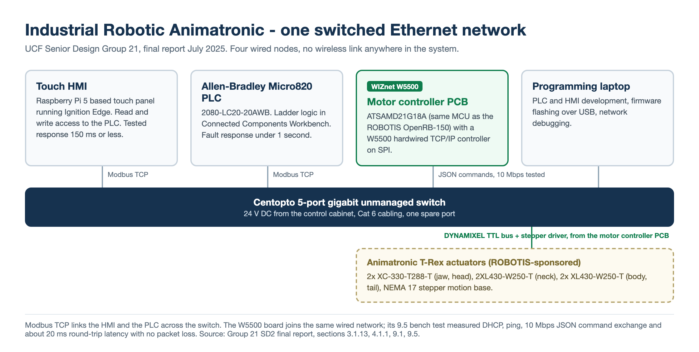
The PLC is an Allen-Bradley Micro820 (2080-LC20-20AWB). The report's PLC comparison favored the Micro800 family for its $200 to $500 price band and free Connected Components Workbench software, against paid environments like Studio 5000 or TIA Portal. The HMI is a Raspberry Pi 5 based industrial touch panel running Ignition Edge, free to license and not locked to one automation vendor's panels.
Modbus TCP is the system protocol between the HMI and the PLC, letting the panel read status and write commands bidirectionally, as section 4.1.1 spells out. The W5500 motor controller board joins the same switched network as a third endpoint; during testing the team exercised that link with JSON command exchange rather than Modbus registers, a distinction the report itself keeps.
The Three-Chip Trade Study That Selected the W5500
Section 3.2.9 is the part WIZnet readers will want to bookmark. The team scored three Ethernet controllers on protocol support, interface compatibility, memory architecture, throughput, and ease of integration, and recorded the result as Table 3.26.
| Criterion | WIZnet W5500 | ASIX AX11001 | Microchip ENC28J60 |
|---|---|---|---|
| Protocol support | TCP, UDP, IPv4, ICMP, ARP, IGMP, PPPoE | TCP/IP | None, relies on host MCU |
| Host interface | SPI | SPI, UART, I2C | SPI |
| Internal buffer | 32 KB, dedicated to Ethernet | 32 KB + 128 KB flash | 8 KB |
| TCP/IP stack | Full hardware stack | Integrated in 8051 CPU | None |
The reasoning matters more than the grid. The ENC28J60 is a bare MAC and PHY, so every protocol byte lands on the host MCU, and its 8 KB buffer and 20 MHz SPI cap both bandwidth and concurrency. The AX11001 bundles its own 8051 core, which the team judged a poor fit for a system already built around a modern 32-bit MCU and a PLC. The W5500 offloads the full stack in silicon, keeps eight hardware sockets, and runs SPI at up to 80 MHz, which the report notes is quadruple the ENC28J60's bandwidth.
The conclusion is stated flatly: "As a result, the W5500 is selected as the Ethernet controller for this project's embedded communication system." The chip's credentials are cited to the W5500 datasheet version 1.0.2 from November 2013.
An OpenRB-150 Descendant With Ethernet Added
The custom PCB is a motor controller built around the ATSAMD21G18A, a 48 MHz Arm Cortex-M0+ that the report picks partly because it is "the same MCU used in the OpenRB-150," the ROBOTIS DYNAMIXEL controller used during motor bring-up. Table 6.5 even lists the part substitutions made against the OpenRB-150 design, upsizing passives to 0805 to meet course fabrication rules.
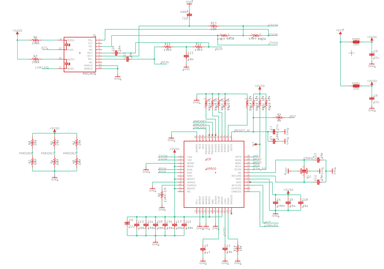
Section 6.1 is candid about the circuit's origin: "The schematic provided from Arduino outlines the integration of the W5500 Ethernet controller and Ethernet port," adapting the MKR ETH Shield reference rather than reinventing it. The write-up still documents the details that make such a layout work: separate 3V3A analog and 3V3D digital supply domains, 100 nF decoupling at the power pins, a 12.4 kOhm 1% bias resistor on EXRES1, a 25 MHz crystal with 10 pF loading, and 49.9 Ohm series terminations into an RJ45 with integrated magnetics. A HALO HCJ11-804SK-L12 jack was chosen in its own connector trade study.
What the Bench Tests Measured
Chapter 9 closes the loop with integration tests. For the W5500, section 9.5 reports DHCP address assignment and ping validation, "a stable 10 Mbps throughput during JSON command exchange," round-trip latency of about 20 ms between the HMI and controller, and no packet loss during sustained use.
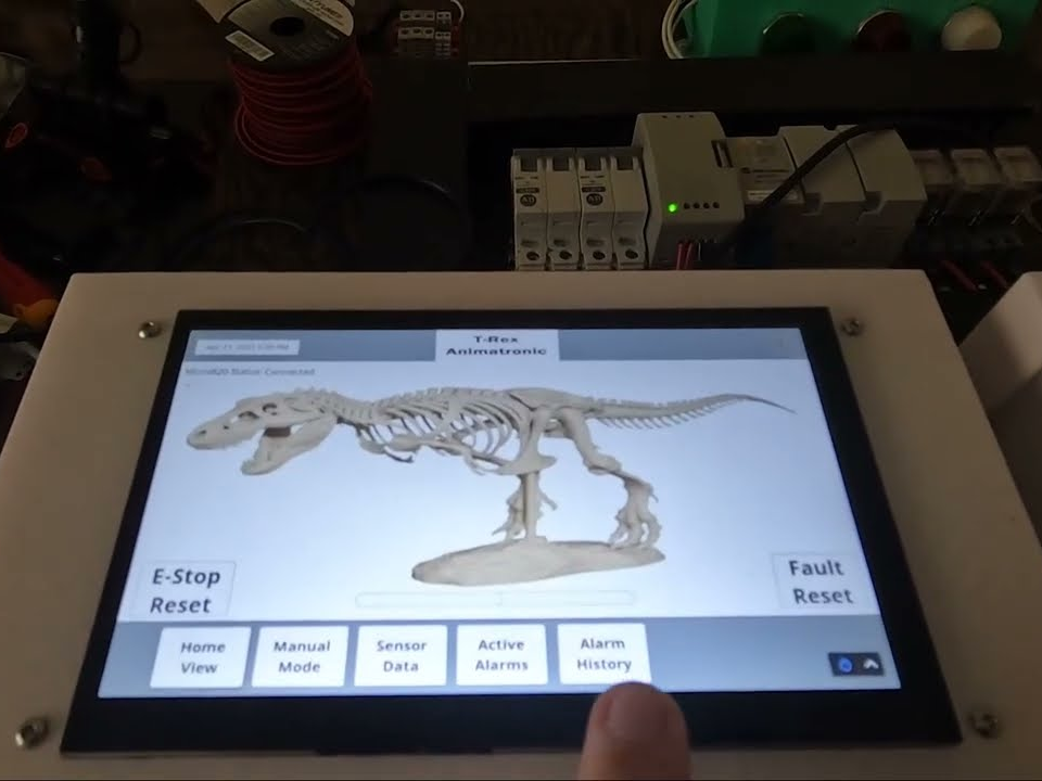
The HMI tests in section 9.1 measured button-to-response latency of 150 ms or less over the Ethernet link to the PLC. The SAMD21 board drew about 25 mA active, with UART and I2C links verified and GPIO toggling checked on a logic analyzer. None of these are heroic numbers, and that is the point: the system meets its sub-second fault response specification on hardware a student team could afford.
Seven Motion Axes on a $1,000 Budget
The animatronic is a 3D-printed PLA T-Rex skeleton with actuators embedded in the model, in the spirit of the Jurassic Park ride animatronics the report cites as prior art. Table 8.1 assigns the axes:
- DYNAMIXEL XC-330-T288-T for the jaw open and close
- A second XC-330-T288-T for 360-degree head rotation
- DYNAMIXEL 2XL430-W250-T for full neck articulation, left-right and up-down
- DYNAMIXEL XL430-W250-T for body sway
- A second XL430-W250-T for tail articulation
- A NEMA 17 stepper motion base, built on a $38.58 Creality Ender 3 V2 bed slinger, for forward and backward travel
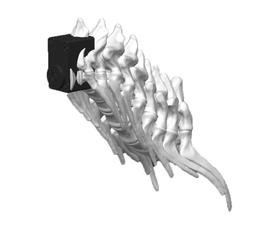
ROBOTIS supplied the five servos under the sponsorship, a package the budget chapter values at $450.45. The build was planned against a $1,000 cap, $250 per member, and the final bill of materials in Table 10.2 itemizes everything from the $65.63 steel enclosure to $20 of Ethernet cables.
Where It Fits and What Is Not Published
The UCF project is a useful reference for anyone putting a W5500 node inside an Allen-Bradley or Ignition environment: it documents why wired Ethernet was mandatory, why the W5500 won on paper, and what the link did on the bench. The trade study prose is a citable answer to a recurring question, what separates the W5500 from a bare MAC/PHY like the ENC28J60.
The limits are equally clear. No firmware or CAD repository is published, so the report and demo videos are the only artifacts; the W5500 circuit adapts Arduino's reference; and the work concluded in July 2025. The report also flags Modbus TCP's lack of built-in security and recommends network segmentation, an honest caveat for any deployment beyond a classroom.
Related WIZnet Maker Projects
The Open-Source Animatronic Puppet Control System with Distributed Network Nodes covers the same craft from the maker side: Ethernet-networked servo nodes syncing puppet motion to audio. The UCF build differs by running industrial PLC and HMI equipment instead of a Linux show controller; together they map the animatronic spectrum.
The Tools Monorepo P1AM DCS/SCADA Control System is the closest network sibling: a P1AM-100 PLC with W5500 Ethernet and Modbus TCP in a SCADA layout. Its PLC itself carries the W5500, while UCF put the chip on a peripheral motor node beside a commercial Micro820.
The HMI Panel for Siemens S7-1200 using USM01 (STM32) + WIZnet W5500 mirrors the HMI side of this architecture. There the W5500 gives a small STM32 panel its path to a Siemens PLC, where UCF used a Raspberry Pi 5 panel and reserved the W5500 for the motion controller.
How to Implement OpenPLC on STM32 with W5500 Ethernet and Modbus TCP shows the fully open alternative: the PLC runtime itself on a W5500-equipped STM32. Readers who like the UCF architecture but not the Allen-Bradley price tag can rebuild the controller side this way.
FAQ
Q. Which WIZnet chip does the UCF Industrial Robotic Animatronic use, and where does it sit? The system uses one WIZnet W5500 on the team's custom motor controller PCB, connected over SPI to an ATSAMD21G18A microcontroller. The board is one of four wired nodes on a gigabit Ethernet switch, alongside the Micro820 PLC, the touch HMI, and a programming laptop.
Q. Why did the team pick the W5500 over the ENC28J60 and AX11001? The report's Table 3.26 trade study credits the W5500's full hardware TCP/IP stack, eight sockets, 32 KB buffer dedicated to Ethernet, and 80 MHz SPI support. The ENC28J60 pushes the whole protocol stack onto the host MCU with only 8 KB of buffer, and the AX11001's built-in 8051 core did not fit a system already designed around a 32-bit MCU and a PLC.
Q. Does the W5500 board speak Modbus TCP in this system? Modbus TCP is the selected protocol between the HMI and the Micro820 PLC, and the report names Modbus TCP workloads among the W5500's strengths. The W5500 test in section 9.5, however, measured JSON command exchange over the same switched network; the report does not document a Modbus register path through the chip.
Q. What software does the UCF animatronic system run? The Micro820 PLC is programmed in ladder logic in the free Connected Components Workbench environment, and the touch HMI runs Ignition Edge under its free license. The SAMD21 motor controller firmware is custom, written with the Arduino framework and flashed over USB.
Q. Can I reproduce this design from the published material? Partially. The 132-page report includes the W5500 circuit walk-through, trade studies, and a complete bill of materials against a $1,000 budget, but no firmware, CAD, or Gerber files are published, and the W5500 circuit itself adapts the Arduino MKR ETH Shield reference schematic.
-
Group 21 SD2 Final Report (PDF, 132 pages)
The full report: Ethernet chip trade study (3.2.9), W5500 circuit (6.1), bench tests (9.5), BOM (10.1)

-
UCF Senior Capstone project site
Group 21 project hub with reports, demo videos, and author LinkedIn profiles
-
8-Page Conference Paper (PDF)
Condensed version of the project, dated 07/07/2025
-
Senior Design 1 demo video
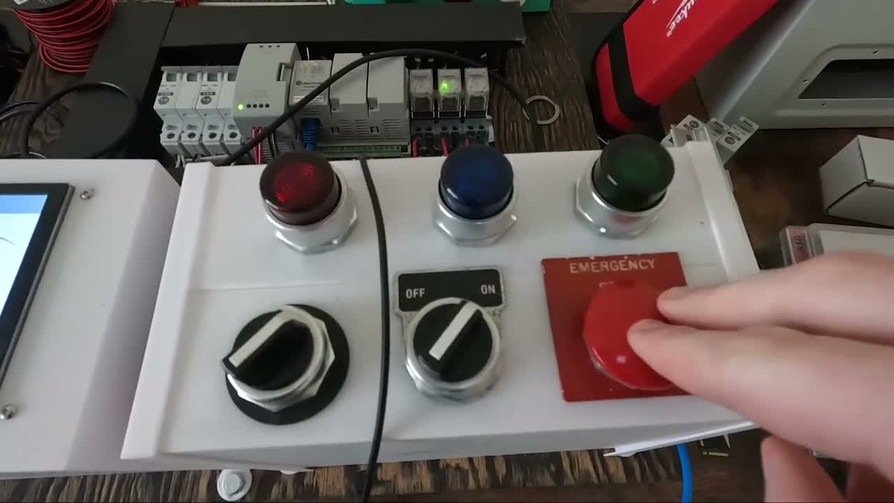
SD1 demo, uploaded to YouTube on July 7, 2025: the T-Rex HMI, E-stop control box, and Micro820 connection live
-
Final demo video
Final demonstration of the integrated animatronic system
-
WIZnet W5500
Hardwired TCP/IP Ethernet controller selected in the trade study
-
ROBOTIS OpenRB-150
The DYNAMIXEL controller whose SAMD21 design the team's motor controller PCB builds on


