


How Does the Eva Wall-Box PoE Sensor Split W5500 Ethernet Across Two Boards?
Alexey Titov's Eva node fits a wall box by splitting in two: sensors and a W5500 on the front PCB, RJ45 and a PoE module on the back.

WIZnet - W5500
x 1

U1 on the front PCB, LQFP-48, listed in the published BOM as WIZNET W5500 (LCSC C32843). Driven over SPI by the ESP32-S3 through the ESPHome ethernet component; TXP/TXN/RXP/RXN cross a board-to-board
A Room Sensor That Hides in the Wall and Runs on One Cable
Alexey Titov is a developer in Moscow who publishes ESPHome and Home Assistant work on GitHub and writes it up on habr. In September 2024 he published a board he had designed himself, and he opened the write-up with a sentence worth repeating: he is not an expert in circuit design or PCB development, and this was his first attempt at either. What came out is a room environment sensor that mounts inside a standard 86 mm wall box, takes its power and its network from a single Ethernet run, and reports to Home Assistant. A WIZnet W5500 is the part that makes the wired half work.
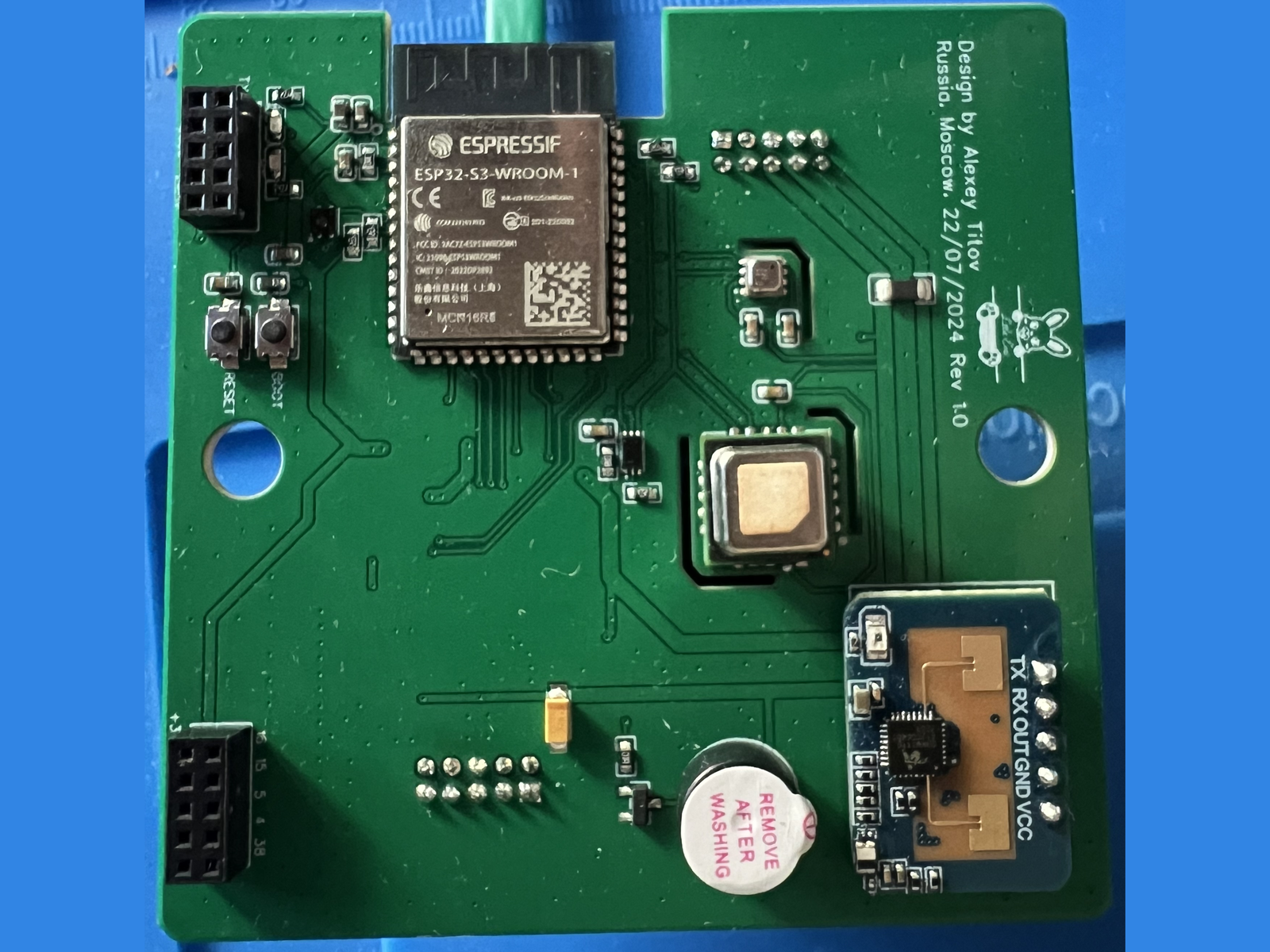
The requirements he set were plain. Temperature, humidity, CO2, air quality, illuminance and human presence had to reach a Home Assistant server. The data had to travel over Ethernet. The device had to be powered by PoE, which means Power over Ethernet, the arrangement where a network switch pushes DC power down the same twisted pair that carries the data. And the whole thing had to fit a Chinese 86 by 86 wall box, the recess that normally holds a light switch.
Why the Board Became Two Boards
The design was drawn in the free online edition of EasyEDA. The interesting constraint arrived at ordering time. He chose NextPCB over the better known JLCPCB because it was reachable from Russia, and he wanted the assembly promotion that puts component placement at twenty dollars. That promotion carries three limits: the board must be no larger than 100 by 100 mm, it must use no more than 100 components in total, and no more than 30 of them may be unique part numbers.
One board holding an ESP32-S3, five sensing devices, a W5500 with its full support network, an RJ45 with magnetics and a PoE front end would have broken the component budget. Splitting the design in half solved it. Each half stayed inside the limits, and the two halves stack inside the wall box on a pair of ten-pin headers.
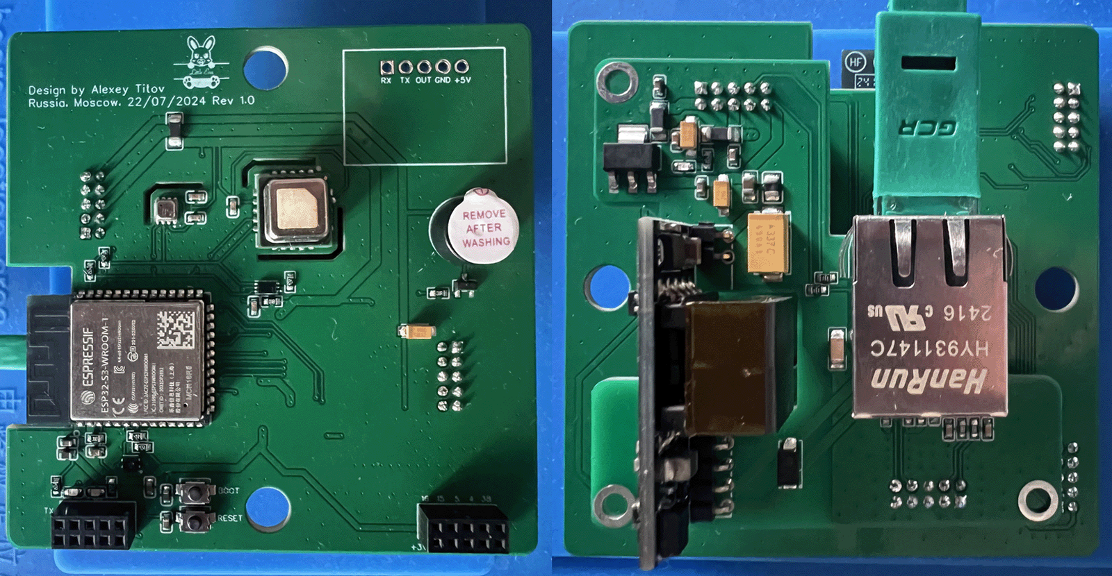
The split also answers the first objection the article received. A reader asked how a device buried in a wall could read room air correctly. Titov replied that only the back part, the one with PoE on it, really sits in the wall. The sensors face the room, the same way a wall-box Wi-Fi access point or a wall-box display does.
Five Sensing Devices on the Room-Facing Side
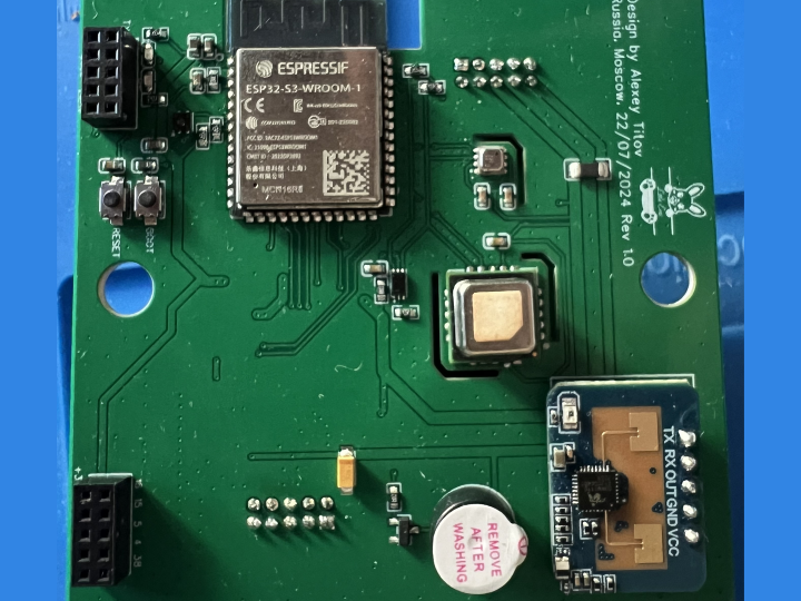
The front board carries an ESP32-S3-WROOM-1 (N16R8) and splits its sensors across two I2C buses. Bus A holds the Sensirion SCD40 for CO2, temperature and humidity, the Bosch BME680 for gas resistance and air quality, and the BH1750FVI for illuminance. Bus B carries the ams ENS210 temperature and humidity sensor on its own, away from the traffic on the first bus. Presence is handled by an HLK-LD2410C, a 24 GHz radar module that reports whether somebody is in the room and how far away they are, wired to the ESP32-S3 over UART at 256000 baud. A buzzer on a LEDC output rounds it out, exposed to Home Assistant as a switch.
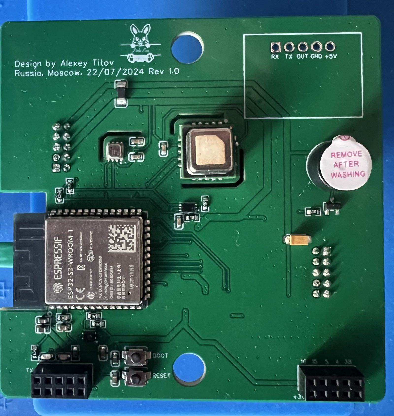
All of it is configured in a single ESPHome file, sensors.yaml. ESPHome is the tool that turns a YAML description of a device into compiled firmware and a set of Home Assistant entities, so there is no hand-written C++ in the repository at all. The one piece of custom logic is a template text sensor that converts the BME680 air quality index into the labels Excellent, Good, Lightly polluted and so on up to Extremely polluted.
The W5500 Block, Copied From the Datasheet
The front schematic gives the W5500 its own bordered block, and it is a textbook implementation. U1 is the W5500 in an LQFP-48 package. X1 is the 25 MHz crystal with 18 pF load capacitors and a 1 MΩ resistor across it. R5 is the 12.4 kΩ reference resistor. R1 through R4 put 33 Ω in series with TXP, TXN, RXP and RXN. Eight 10 kΩ resistors strap the reserved and PMODE pins, and three more pull SCS, INT and RST up to the digital 3.3 V rail. Six 100 nF capacitors and a 10 uF bulk cap sit on the analog supply, which is separated from the digital rail by a 100 Ω ferrite bead.
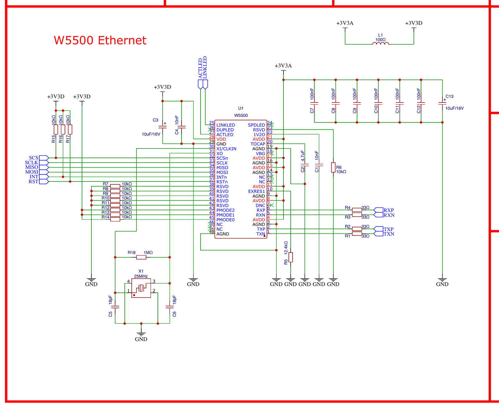
Where the reference came from is written at the bottom of the same drawing. The sheet ends with a short list of datasheet links, and the first line is WIZnet's own W5500_ds_v110e.pdf on docs.wiznet.io. For a first attempt at schematic capture, that is the whole story: read the vendor document, place the recommended support parts, and the wired interface works.
The firmware side is six lines. The ethernet: block in sensors.yaml declares type: W5500 with clk on GPIO10, mosi on GPIO12, miso on GPIO11, cs on GPIO9, interrupt on GPIO13 and reset on GPIO14. Those six pins match the ESP32-S3 symbol in the schematic exactly, which is a useful thing for anyone reusing the design, because the drawing and the configuration verify each other.
Where the PoE Comes In
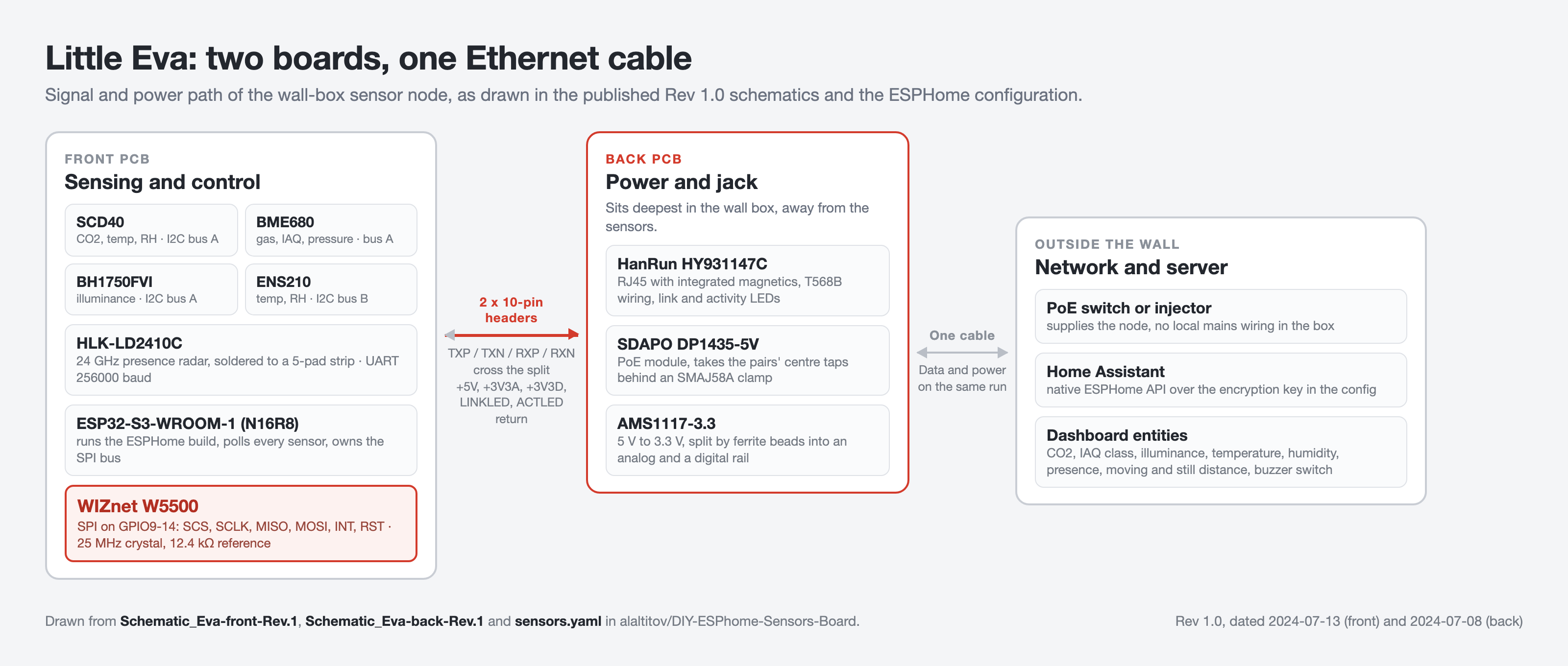
The back board is the power and connector half. The jack is a HanRun HY931147C-M01, an RJ45 with the isolation magnetics built into the housing, wired to the T568B pinout. The centre taps of the two data pairs feed an SMAJ58A transient suppressor and then an SDAPO DP1435-5V module, the part that negotiates PoE and produces 5 V. An AMS1117-3.3 drops that to 3.3 V, and a pair of 100 Ω ferrite beads splits the result into separate analog and digital rails before either one crosses back to the front board.
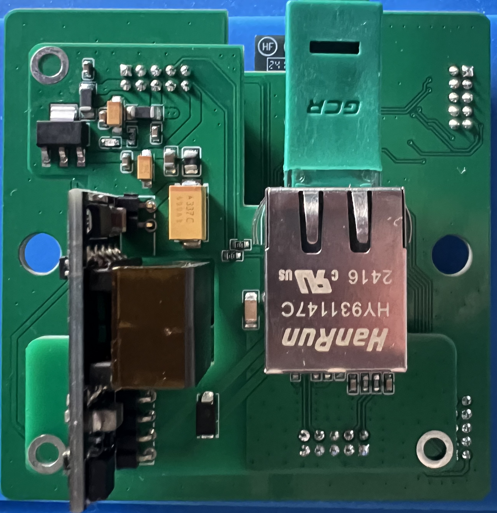
Because the RJ45 lives here and the W5500 lives on the other board, the four differential lines have to cross the split. They do it through one of the two ten-pin headers, alongside ground; the second header carries 5 V, the two 3.3 V rails and the link and activity LED signals back the other way.
From Sensor Pin to Home Assistant Entity
Put the two halves together and the path is short. The sensors talk I2C and UART to the ESP32-S3. The ESP32-S3 talks SPI to the W5500. The W5500 hands the differential pairs across the headers to the magnetics and the jack. One cable leaves the wall carrying both the data and the power the node runs on. At the far end, ESPHome's native API, secured with an encryption key kept in the ESPHome secrets file, delivers every reading to Home Assistant.
Firmware updates take the same route. The board has no USB connector, so the first flash goes in over TX, RX and GND with a serial adapter, and after that the ESPHome OTA platform handles it over the network.
What the Dashboard Shows, Including the Part Still Being Fixed
The published Home Assistant screenshot is the proof the thing runs. CO2 in parts per million from the SCD40, illuminance in lux from the BH1750, pressure and air quality index from the BME680 with its classification in words, temperature and humidity from three separate sensors, and from the radar a presence flag plus moving and still distance in centimetres with an energy percentage for each.
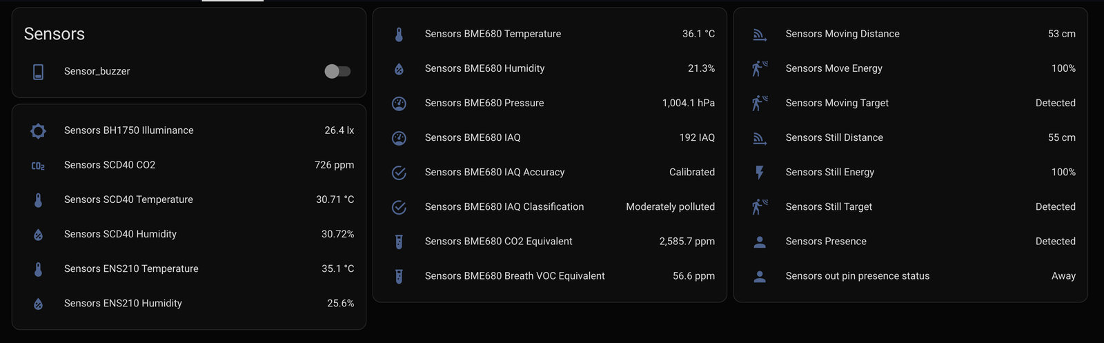
That same screenshot shows the problem Titov flags at the end of his article. The three temperature sensors do not agree: the SCD40 reads 30.71 °C while the ENS210 reads 35.1 °C and the BME680 reads 36.1 °C. His diagnosis is that the sensors are sensitive to heat and noise from the other parts on the board, and in the comments he narrows the source to the second board with the power section rather than to the ESP32-S3 module. He also reports that connecting the two boards with wires instead of the pin headers already brings the SCD40 within a degree of a mercury thermometer. The planned front-board revision follows from that: separate analog and digital grounds, ground pours pulled away from the sensors, the sensors themselves spaced differently, and better routing of the board outline.
What Is Published and What Is Not
The hardware is fully open. Both schematics, both bills of materials with LCSC part numbers, both Gerber packages and both pick-and-place files are in the repository under an MIT licence, along with the complete ESPHome configuration. That is enough to have the boards made and populated.
Several things are not published, and it is worth being clear about them. There is no enclosure; the article and the README both list it as future work, and the author has said the enclosure is the harder half of the problem. The improved schematic and layout he mentions in a later comment have not been posted, so Rev 1.0 is still the only public version. No current draw, PoE class, or link stability figures appear anywhere. There is no price for a finished unit; the bills of materials carry LCSC unit prices for the parts, which is a different thing. And no published photograph shows the W5500 itself, because the front board was shot from its sensor side and the back board from its connector side. The evidence for the chip is the schematic block, the BOM row, and the ESPHome configuration.
Where It Went After Publication
By August 2026 the habr article had been read about 15,300 times, bookmarked 80 times and drawn 28 comments, and the repository had 9 stars with the last commit still dated September 2024. The interesting signal is not the counts but the one open issue. In March 2025 a reader asked whether a Zigbee version was possible and added that he needed roughly ten units and was willing to help fund them, because the only wall-box CO2 sensor he could find on the market was priced out of reach. Titov's answer was that Zigbee had not been considered, partly because ESPHome at the time did not support the ESP32-C and ESP32-H parts that carry a Zigbee radio, and that the project was paused behind other work.
Those other projects are visible on his GitHub profile, and they stayed on the same theme. He published a Home Assistant Lovelace card for these sensor readings eleven days after the board repository went up, and he has since written ESPHome firmware for commercial wall panels, including a Waveshare 86-format panel with Ethernet that he also reviewed on habr. The wall-box-plus-wired-networking idea outlived the prototype that started it.
Related WIZnet Maker Projects
MultiSensor-V2 is the closest neighbour: also an ESP32-S3 with a W5500 and PoE, also a room node for Home Assistant. The difference is maturity and scope, since that project has been through several hardware generations and adds local wake-word audio, an enclosure and installation photos. Reading the two together shows how much of a W5500 room node is settled practice and how much is still a matter of taste.
ESPHome-W5500-Ethernet-on-ESP32-boards covers the step before this one: getting the W5500 running over SPI on off-the-shelf ESP32 boards while keeping I2C free for sensors. Eva is what that experiment looks like once it becomes a dedicated PCB, and the pin choices in both are worth comparing.
sensormeter-poe takes the same PoE environmental sensor idea into server rooms and network closets, where the reporting protocol matters more than the form factor. Between the two you can see how far the physical constraints, not the electronics, drive the design of a wired sensor node.
FAQ
Q. What does this project use the W5500 for? It is the Ethernet controller for the node. The ESP32-S3 drives it over SPI on GPIO9 through GPIO14, and the W5500's four differential lines cross a board-to-board header to reach the RJ45 jack with integrated magnetics on the second PCB.
Q. Why use wired Ethernet instead of the ESP32-S3's own Wi-Fi? The published configuration has no Wi-Fi section at all. In the article comments the author explains that presence-driven lighting automation needs a reading roughly every second, and that a device fed by PoE never needs charging or a battery change, which suits a unit sealed into a wall.
Q. Can I have these boards made myself? Yes. Both schematics, both bills of materials with LCSC part numbers, both Gerber packages and both pick-and-place files are published under an MIT licence, together with the ESPHome configuration. There is no enclosure design, so that part is left to the builder.
Q. Why is the design split across two PCBs? The assembly service promotion the author used limits a board to 100 by 100 mm, 100 components and 30 unique part numbers. One board with the microcontroller, five sensing devices, the W5500 and the PoE front end would have exceeded that, so the design was cut in half and joined with two ten-pin headers.
Q. Why do the three temperature sensors disagree on the dashboard? The author attributes it to heat and electrical noise from nearby components, and points at the power board rather than the microcontroller module. He reports that wiring the two boards together instead of stacking them on pin headers already brings the SCD40 close to a reference thermometer, and the next front-board revision is planned to split the ground planes and re-space the sensors.
-
Original habr article
Alexey Titov's write-up in Russian: design goals, the EasyEDA and NextPCB route, the assembly limits that forced the two-board split, the CircuitPython to ESPHome switch, and the planned front-board r

-
DIY ESPhome Sensors Board repository
Primary source under MIT: schematics, bills of materials, Gerber packages, pick-and-place files, ESPHome configuration and the project photographs.
-
Front PCB schematic Rev 1.0
Contains the bordered W5500 Ethernet block with the 25 MHz crystal, 12.4 kOhm reference, 33 Ohm series resistors and SPI wiring to the ESP32-S3, plus the datasheet reference list.
-
Back PCB schematic Rev 1.0
HanRun HY931147C magjack with T568B wiring, SMAJ58A clamp, SDAPO DP1435-5V PoE module, AMS1117-3.3 regulator and the split analog and digital rails.
-
Front PCB bill of materials
28 line items including the W5500 (WIZNET, LQFP-48, LCSC C32843), the ESP32-S3-WROOM-1-N16R8 and all four environment sensors.
-
ESPHome Ethernet component
Official documentation for the ethernet block used in sensors.yaml, including the W5500 SPI pin options.
-
WIZnet W5500 product documentation
Official reference for the Ethernet controller. The project schematic cites the W5500 datasheet on docs.wiznet.io as its first reference.


