
YB-ESP32-S3-ETH - Ethernet + WiFi Development Board
General purpose development board based on WIZnet's W5500 and Espressif's ESP32-S3 MCU. With RJ45 Ethernet connector, PHY bridge chip W5500, USB-C, 2 LEDs

WIZnet - W5500
x 1
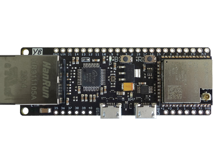
YB-ESP32-S3-ETH board overview:
The board enables you to easily realize ESP32 projects with Ethernet or combined Ethernet/WiFi support. A collection of software examples (for PlatformIO and/or ArduinoIDE) are available on https://github.com/yellobyte/YB-ESP32-S3-ETH.
The densly populated YB-ESP32-S3-ETH board provides multiple GPIO pins and is still highly breadboard compatible for it leaves one row of accessible breadboard contacts on either side of the board. All I/O ports (GPIOx) are labeled on both sides of the board.
If WiFi/BT is needed instead of or additionally to an Ethernet connection then the external 2.4GHz WLAN antenna can be connected to the onboard WROOM-1U module. The connector is compatible with the following standards: U.FL (Hirose), MHF-I (I-PEX) and AMC (Amphen).
- ESP32-S3-WROOM-1U-N8R2 module with 8MB Flash, 2MB PSRAM or without ESP32-S3-WROOM module
- WiFi/BT IPEX antenna connector (only boards with ESP32-S3-WROOM module)
- RJ45 10M/100M Ethernet connector driven by onboard PHY controller chip Wiznet W5500
- the W5500 pins required to control the chip are hardwired to the ESP32-S3 GPIOs as follows:
- MOSI - GPIO11, MISO - GPIO13, SCK - GPIO12 (SPI bus data communication)
- SCS - GPIO14 (chip select, required for SPI bus control)
- RST - GPIO21 (only if solder bridge on bottom is closed, chip reset, needed for chip reset without resetting the whole board)
- INT - GPIO18 (only if solder bridge on bottom is closed, seldomly needed)
- control LEDs. One LED labeled 'P' is connected to the 3.3V rail to indicate board power and the other LED labeled 'IO47' is connected to GPIO47 which can be used as status LED, for debugging purposes etc.
- USB-C port connected to the onboard CH334 USB hub chip. This allows for simultaneous JTAG debugging and serial output as well as software upload (e.g. via ArduinoIDE, VSCode/PlatformIO etc). The ESP32-S3 contains an inbuild JTAG adapter hence debugging becomes fairly easy.
- hardware logic for automatic software uploads (supported by most Development IDEs) via USB-C port using the onboard CH343 USB-UART bridge chip.
- pushbuttons. One is labeled 'R' and resets the ESP32-S3 (shorts EN pin to ground) and the other one is labeled 'B' and shorts GPIO0 to ground when pressed. The latter is sometimes needed to force the board into boot mode.
- lots of available GPIOs next to the ones already mentioned above.
It's easy. Here you find the Eagle library file yb-esp32-s3-eth.lbr containing the board. Most other PCB design software (e.g. KiCad) are able to import and use Eagle lib files.
-
Examples

-
Board Schematics & Docu
-
Board Pin Layout