


pla1
이 프로젝트는 산업용 PLC 계열 장치로 보이며, 웹 대시보드, MQTT, Modbus, 원격 관리 같은 핵심 네트워크 기능이 W5500 이더넷 경로에 실제로 연결됩니다. WiFi와 LTE 대체 경로도 있지만, W5500은 보드 V3의 실사용 네트워크 인터페이스로 통합되어 있습니다.
★ W5500이 단순 옵션이 아니라 보드 V3의 고정 하드웨어이고, 웹 UI와 MQTT 같은 핵심 서비스가 실제 이더넷 경로를 타도록 설계되어 있어 적극적 사용으로 보는 것이 맞습니다.
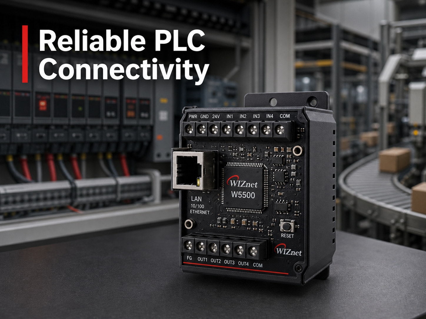

WIZnet - W5500
x 1

요약
pla1(GitHub: xheronimo/pla1)은 ESP32/ESP32-S3 위에서 동작하는 산업용 PLC급 펌웨어입니다. Modbus RTU·I2C·1-Wire로 들어오는 현장 신호를 하나의 신호 테이블로 통합하고, 알람을 MQTT·Telegram·SMS로 전파하며, 유선 이더넷(V3 보드는 WIZnet W5500)·WiFi·4G(SIM7600) 세 회선을 자동 전환하는 통신 페일오버 구조가 핵심입니다. 아직 커뮤니티에 공개되지 않은 1인 개발 단계이지만, 산업 게이트웨이가 갖춰야 할 요소를 대부분 갖춘 완성도 높은 구조입니다.
개요
배전반·기계실처럼 RS485 필드버스가 있으면서 유선 인터넷이 불안정한 현장에서는, 계측값을 놓치지 않고 알람을 확실히 전파하는 통신 안정성이 곧 운영 신뢰도입니다. pla1은 이 문제를 하나의 ESP32 보드 위에서 필드버스 수집·알람 판정·다중 통신 회선 전환까지 전부 해결하려는 시도입니다. 다만 저장소 자체는 2026년 3월 한 개발자(xheronimo)가 3일간 집중 업로드한 상태로, README나 외부 도입 사례, Star·Fork 등 커뮤니티 검증은 확인되지 않습니다. 이 글은 공개된 소스코드를 근거로 구조와 WIZnet 활용 지점을 분석합니다.
아키텍처
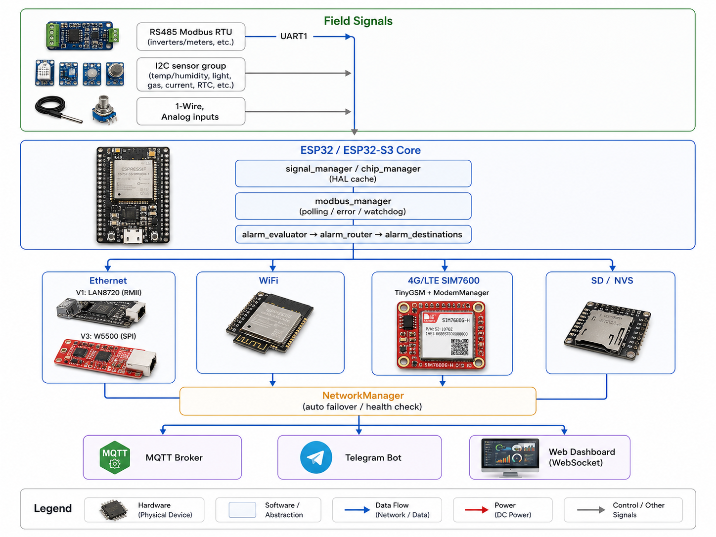
FreeRTOS 태스크가 폴링·알람·통신·워치독을 독립적으로 실행해, 한 회선이나 한 필드 장치의 응답 지연이 전체 시스템을 멈추지 않도록 설계돼 있습니다.
기술 배경
Modbus RTU는 마스터가 슬레이브의 홀딩 레지스터·코일을 폴링하는 산업 표준 시리얼 프로토콜입니다. RS485 물리 계층 위에서 8비트 바이너리 프레임과 CRC로 오류를 검출합니다. pla1의 modbus_manager는 슬레이브별로 그룹을 구성해 폴링하고, 에러가 5회 누적되면 해당 슬레이브를 비활성 처리해 통신 장애가 전체 폴링 루프를 막지 않게 합니다.
→ 참고: MODBUS over Serial Line Specification, Modbus 사양 목록
다중 WAN 페일오버는 유선·무선·셀룰러 등 서로 다른 회선을 조합해, 하나가 끊겨도 다음 가용 회선으로 트래픽을 넘기는 구조입니다. 업계에서는 유선을 주 회선으로 두고 4G/LTE를 백업으로 쓰는 방식이 일반적이며, 회선 전환 시 플래핑을 막는 지연(damping) 처리가 안정성의 핵심으로 꼽힙니다. pla1의 NetworkManager는 5초 주기 monitorTask로 현재 회선 상태를 감시하고 30초 주기 recoveryTask로 상위 우선순위 회선(이더넷 > WiFi > 4G로 추정)의 복구를 시도하는 구조로, 이 원칙을 그대로 따르고 있습니다.
→ 참고: IoT Gateway Backhaul Guide: Ethernet, Wi-Fi, or 4G/5G
MQTT는 발행/구독 기반의 경량 메시징 프로토콜로, 대역폭이 제한된 M2M·IoT 환경을 위해 설계됐습니다. pla1은 MQTT를 알람 채널 중 하나이자 원격 명령·설정 스냅샷 전송 창구로 사용합니다(mqtt_manager, mqtt_commands, mqtt_snapshot).
→ 참고: MQTT Version 5.0, OASIS Standard
기술 특징
- 태스크 분리: task_modbus/task_mqtt/task_alarm_dispatcher/task_watchdog 등이 FreeRTOS 위에서 독립 실행되어, 필드버스 응답 지연이나 네트워크 재연결이 알람 처리를 막지 않음
- 알람 라우팅:
AlarmChannel비트마스크(MQTT/SMS/Telegram/Log)로 목적지별 채널 조합을 자유롭게 구성 - 동적 신호 관리: signal_json_loader/config_loader가 JSON 기반으로 신호·설정을 로드해, 펌웨어 재컴파일 없이 현장별 구성을 바꿀 수 있는 구조
WIZnet 적용 — V3 보드의 W5500
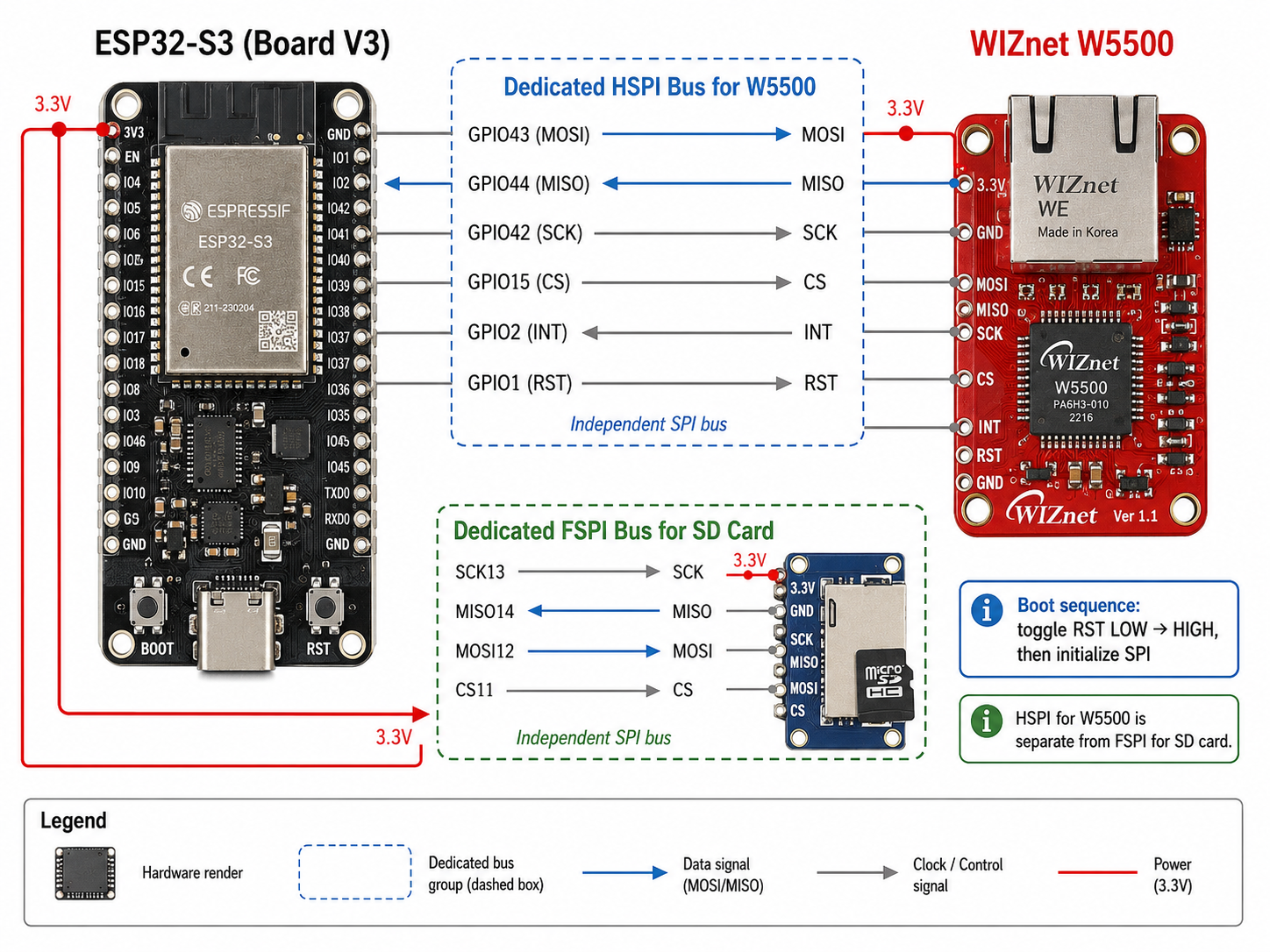
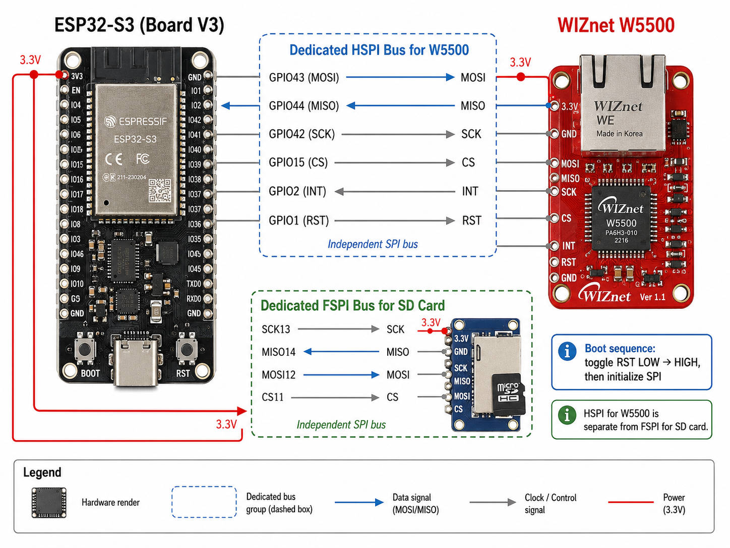
V3 보드(ESP32-S3)는 W5500을 SPI로 연결한 유선 이더넷을 씁니다. 핀맵은 MOSI 43, MISO 44, SCK 42, CS 15, INT 2, RST 1이며, SD카드·다른 SPI 장치와 겹치지 않도록 별도의 HSPI 버스를 W5500 전용으로 분리했습니다.
부팅 시 흐름을 번호로 정리하면 다음과 같습니다.
W5500_RST핀을 LOW → HIGH로 토글해 칩을 하드웨어 리셋- 전용 SPI 버스(HSPI)를 W5500 핀 조합으로 초기화
NetworkLoader가 이 SPI 객체를 넘겨받아 IP 설정을 로드- 이후 Modbus TCP나 MQTT 트래픽이 필요하면, ESP32 코어는 패킷을 조립·해석하지 않고 W5500이 TCP/IP 스택 전체를 하드웨어로 처리하고 결과만 MCU에 전달
비유하자면 ESP32는 "본사 사무실"이고 W5500은 "우체국"입니다. 본사는 편지 내용(데이터)만 쓰고, 봉투 포장·주소 확인·배달 경로 관리(TCP/IP 패킷 처리)는 전부 우체국이 맡습니다. 만약 이 칩이 없었다면 ESP32는 lwIP 소프트웨어 스택으로 직접 패킷을 처리해야 해, Modbus 폴링·알람 판정·디스플레이 갱신과 네트워크 인터럽트가 같은 코어 자원을 다투게 됩니다.
V1 보드가 쓰는 LAN8720(RMII PHY, MAC은 ESP32 내장)과 비교하면 차이가 뚜렷합니다. LAN8720 구조는 TCP/IP 스택을 여전히 ESP32의 소프트웨어(lwIP)가 처리하는 반면, W5500 구조는 그 부담을 칩 밖으로 완전히 덜어냅니다. 한 프로젝트 안에 두 방식이 나란히 존재한다는 점에서, pla1은 "MCU 내장 MAC" 방식과 "SPI 하드 오프로드" 방식의 차이를 실물로 보여주는 사례입니다.
WIZnet Makers 유사 사례
- platform-jwplc (JWPLC Basic): ESP32 + W5500 기반 산업용 PLC 보드 패키지. pla1처럼 코드 스스로를 "PLC"로 지칭하지만, 페루 기업 JW Control이 실제 판매하는 상용 제품 BSP라는 점에서 pla1(1인 개발, 미검증 단계)과 대조됩니다.
→ 프로젝트 링크: https://maker.wiznet.io/scott/projects/platform-jwplc - esp32s3-modbus-gateway-gemini: ESP32-S3 + WIZnet W5100S + Modbus RTU/TCP + MQTT + 웹 설정 UI 조합. 소프트웨어 스택이 가장 근접하지만 4G 페일오버는 없어, pla1의 "3중 통신" 구조가 상대적 차별점으로 드러납니다.
→ 프로젝트 링크: https://maker.wiznet.io/matthew/projects/esp32s3-modbus-gateway-gemini - Zero Downtime for 3 Years: Industrial IoT Gateway with W5500 & RT-Thread: W5500 기반 산업 IIoT 게이트웨이로 "무중단"을 핵심 가치로 내세운 사례. RTOS는 다르지만(RT-Thread) pla1의 워치독·안전모드·페일오버 설계와 문제의식이 겹칩니다.
→ 프로젝트 링크: https://maker.wiznet.io/Grace_Koo/projects/zero-downtime-for-3-years-a-battle-tested-industrial-iot-gateway-with-w5500-rt-thread/
세 사례 모두 MCU·RTOS는 제각각이지만, W5500/W5100S가 "산업용 유선 이더넷 오프로더"라는 동일한 역할로 반복 채택된다는 공통점이 있습니다.
| 항목 | pla1 (본 프로젝트) | platform-jwplc | esp32s3-modbus-gateway-gemini | Zero Downtime (W5500+RT-Thread) |
|---|---|---|---|---|
| MCU | ESP32 / ESP32-S3 | ESP32-WROOM-32E | ESP32-S3 | 미상 |
| WIZnet 칩 | W5500(V3) | W5500 | W5100S | W5500 |
| 통신 회선 | 이더넷+WiFi+4G 3중 | 이더넷+RS485 | 이더넷+WiFi | 이더넷 중심 |
| 실사용 검증 | 미상(1인 개발) | 상용 판매(JW Control) | 미상 | "3년 무중단" 주장(근거 별도 확인 필요) |
비즈니스 가치
외부(고객/시장) 관점: 배전반·기계실 등 전기적 노이즈가 많은 현장에서는 무선보다 유선 이더넷의 링크 안정성이 중요합니다. 여기에 4G 백업까지 더하면, 유선 회선 공사가 어려운 원격지에서도 계측 데이터를 놓치지 않는 3중화 게이트웨이가 됩니다.
내부(WIZnet) 관점: ESP32-S3처럼 코어 성능이 충분한 MCU에서도 여전히 SPI 분리형 하드 이더넷(W5500)을 채택했다는 점은, "MCU 성능이 올라가도 TCP/IP 하드웨어 오프로딩의 존재 가치는 유지된다"는 포지셔닝을 뒷받침하는 사례입니다.
한계 및 개선 방향
- 커뮤니티 검증 없음(0 Star/Fork, 이슈 트래킹 없음) — 실사용 안정성 근거가 아직 부족합니다. 문서화와 공개 테스트 로그를 갖추면 신뢰도를 높일 수 있습니다.
ModemManager.h가 현재 스텁 상태(getStatus()가 고정값 반환)로, 4G 페일오버 경로가 완전히 마감되지 않은 것으로 보입니다 [추정]. TinyGSM 연동을 마무리하면 3중 페일오버가 실질적으로 완성됩니다.board_v3.h에 V1 정의가 일부 그대로 남아있어 리팩터링 중인 상태로 보입니다 — 보드별 헤더를 명확히 분리하면 유지보수성이 개선됩니다.
FAQ
Q1. RS485+이더넷+4G를 동시에 구성할 수 있나요? 코드 구조상 세 회선을 동시에 초기화하도록 설계돼 있지만, 4G 경로(ModemManager)가 스텁 상태라 현재 시점의 완전한 3중 동시 운용 검증 여부는 확인되지 않습니다.
Q2. V1과 V3 보드 중 어느 쪽을 선택해야 하나요? 유선 이더넷만 필요하고 비용을 아끼려면 LAN8720 기반 V1, SPI 버스 분리로 안정적인 하드 오프로딩과 확장성이 필요하면 W5500 기반 V3가 적합합니다.
Q3. 신호(포인트) 개수를 얼마나 확장할 수 있나요? signal_manager가 JSON 기반 동적 로딩 구조라 신호 추가 자체는 용이하지만, 최대 개수나 메모리 한계는 공개 코드에서 확인되지 않습니다.
Q4. OTA(원격 펌웨어 업데이트)를 지원하나요? platformio.ini의 라이브러리 목록과 공개된 소스에서 OTA 관련 코드는 확인되지 않습니다.
Q5. 유지보수는 어떻게 하나요? SD카드 이벤트 로그(SDMgr::logEvent)와 부팅 사유 기록(boot_reason)이 있어 현장 디버깅에 활용할 수 있지만, 원격 진단 도구가 별도로 확인되지는 않습니다.
From RS485 to 4G, Never Offline: An ESP32-S3 Industrial PLC Gateway Built on W5500
Summary / TL;DR
pla1 (GitHub: xheronimo/pla1) is industrial PLC-grade firmware running on ESP32/ESP32-S3. It unifies field signals from Modbus RTU, I2C, and 1-Wire into a single signal table, routes alarms over MQTT, Telegram, and SMS, and automatically fails over between three uplinks — wired Ethernet (WIZnet W5500 on the V3 board), WiFi, and 4G (SIM7600). It's still a solo, unpublished project, but the architecture already covers most of what a real industrial gateway needs.
Overview
In switchgear rooms and equipment rooms where an RS485 fieldbus is present but wired internet is unreliable, not missing a reading and reliably delivering alarms is what operational trust comes down to. pla1 attempts to solve all of that on a single ESP32 board: field-bus acquisition, alarm evaluation, and multi-link failover in one firmware image. That said, the repository itself is a burst of commits from a single developer (xheronimo) over three days in March 2026 — there's no README, no external adoption evidence, and no community validation (stars, forks). This article analyzes the architecture and WIZnet usage strictly from the published source code.
Architecture
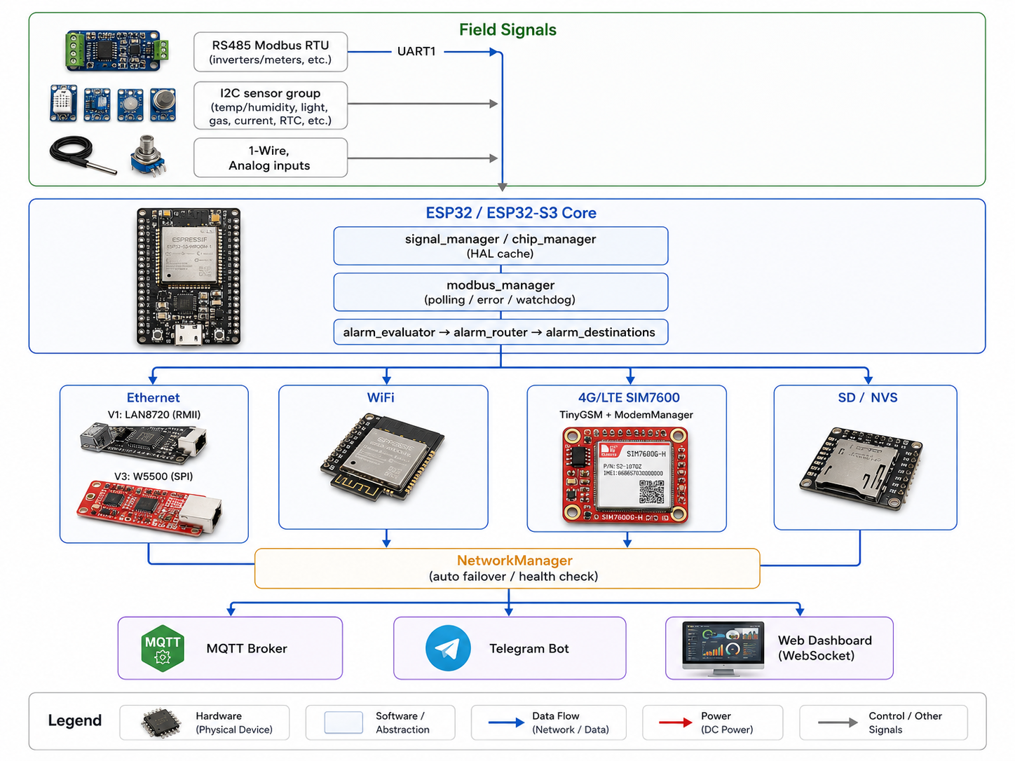
FreeRTOS tasks run polling, alarming, networking, and the watchdog independently, so a slow field device or a stalled link never blocks the rest of the system.
Technology Background
Modbus RTU is the industrial-standard serial protocol where a master polls holding registers and coils on slave devices. Running over an RS485 physical layer, it frames data as 8-bit binary with CRC error checking. pla1's modbus_manager groups slaves for polling and marks a slave inactive after 5 accumulated errors, so a failing field device doesn't stall the rest of the polling loop.
→ Reference: MODBUS over Serial Line Specification, Modbus specifications index
Multi-WAN failover combines links of different kinds — wired, wireless, cellular — so traffic moves to the next available link when one drops. Common industry practice keeps a wired link primary with 4G/LTE as backup, and damping delays during link switching are considered key to stability. pla1's NetworkManager follows this exact pattern: a 5-second monitorTask watches the active link's health, and a 30-second recoveryTask attempts to recover higher-priority links (Ethernet > WiFi > 4G, inferred).
→ Reference: IoT Gateway Backhaul Guide: Ethernet, Wi-Fi, or 4G/5G
MQTT is a lightweight publish/subscribe messaging protocol designed for bandwidth-constrained M2M and IoT environments. pla1 uses MQTT as one of its alarm channels and also as a channel for remote commands and configuration snapshots (mqtt_manager, mqtt_commands, mqtt_snapshot).
→ Reference: MQTT Version 5.0, OASIS Standard
Technical Highlights
- Task separation: task_modbus/task_mqtt/task_alarm_dispatcher/task_watchdog and others run as independent FreeRTOS tasks, so fieldbus latency or a network reconnect never blocks alarm processing
- Alarm routing: an
AlarmChannelbitmask (MQTT/SMS/Telegram/Log) lets destinations mix and match channels freely - Dynamic signal management: signal_json_loader/config_loader load signals and settings from JSON, so a site's configuration can change without recompiling firmware
Where WIZnet Fits — W5500 on the V3 board
The V3 board (ESP32-S3) uses W5500 over SPI for wired Ethernet. The pinout is MOSI 43, MISO 44, SCK 42, CS 15, INT 2, RST 1, and the firmware puts W5500 on its own dedicated HSPI bus so it never contends with the SD card or other SPI peripherals.
The boot sequence, step by step:
- Toggle the
W5500_RSTpin LOW then HIGH to hardware-reset the chip - Initialize a dedicated SPI bus (HSPI) with the W5500 pin set
NetworkLoadertakes that SPI object and loads the IP configuration- From then on, whenever Modbus TCP or MQTT traffic needs to move, the ESP32 core never assembles or parses packets — W5500 handles the entire TCP/IP stack in hardware and only hands the result to the MCU
Think of ESP32 as the "head office" and W5500 as the "post office." The head office only writes the letter's contents (the data); envelope packing, address verification, and delivery routing (TCP/IP packet handling) are entirely the post office's job. Without this chip, ESP32 would have to process packets itself through the lwIP software stack, and Modbus polling, alarm evaluation, and display updates would all be competing with network interrupts for the same core.
The contrast with the V1 board's LAN8720 (an RMII PHY, with the MAC built into ESP32) is instructive. With LAN8720, the TCP/IP stack is still handled by ESP32's own software (lwIP); with W5500, that burden is offloaded off-chip entirely. Having both approaches side by side in one codebase makes pla1 a concrete illustration of the difference between an "MCU-integrated MAC" design and an "SPI hardware-offload" design.
Similar Projects on WIZnet Makers
- platform-jwplc (JWPLC Basic): An ESP32 + W5500 industrial PLC board package. Like pla1, its code refers to itself as "the PLC," but it's the BSP behind a commercial product actually sold by Peru-based JW Control — a useful contrast to pla1's unvalidated, solo-developer stage.
→ Project link: https://maker.wiznet.io/scott/projects/platform-jwplc - esp32s3-modbus-gateway-gemini: Combines ESP32-S3, WIZnet W5100S, Modbus RTU/TCP, MQTT, and a web configuration UI. The closest software stack match, but it has no 4G failover — which makes pla1's three-way link redundancy stand out by comparison.
→ Project link: https://maker.wiznet.io/matthew/projects/esp32s3-modbus-gateway-gemini - Zero Downtime for 3 Years: Industrial IoT Gateway with W5500 & RT-Thread: A W5500-based industrial IIoT gateway built around an uptime story. The RTOS differs (RT-Thread), but the underlying concerns — watchdogs, safe mode, failover — mirror pla1's design.
→ Project link: https://maker.wiznet.io/Grace_Koo/projects/zero-downtime-for-3-years-a-battle-tested-industrial-iot-gateway-with-w5500-rt-thread/
Despite differing MCUs and RTOSes, all three share one pattern: W5500/W5100S keeps getting chosen for the same role — industrial-grade wired Ethernet offloading.
| Item | pla1 (this project) | platform-jwplc | esp32s3-modbus-gateway-gemini | Zero Downtime (W5500+RT-Thread) |
|---|---|---|---|---|
| MCU | ESP32 / ESP32-S3 | ESP32-WROOM-32E | ESP32-S3 | Not specified |
| WIZnet chip | W5500 (V3) | W5500 | W5100S | W5500 |
| Uplinks | Ethernet+WiFi+4G (triple) | Ethernet+RS485 | Ethernet+WiFi | Ethernet-centric |
| Real-world validation | Unconfirmed (solo dev) | Commercially sold (JW Control) | Unconfirmed | Claims "3 years zero downtime" (evidence needs separate verification) |
Business Value / Use Cases
External (customer/market) perspective: In electrically noisy sites like switchgear rooms and equipment rooms, wired Ethernet's link stability matters more than wireless. Adding 4G backup on top turns the gateway into a triple-redundant system that keeps collecting data even at remote sites where running a wired line isn't practical.
Internal (WIZnet) perspective: The fact that a project still chooses an SPI-based hardwired Ethernet chip (W5500) even on a core as capable as ESP32-S3 supports the positioning that TCP/IP hardware offloading keeps its value even as MCU performance climbs.
Limitations and Future Improvements
- No community validation (0 stars/forks, no issue tracking) — there isn't yet evidence of real-world reliability. Documentation and public test logs would help build trust.
ModemManager.his currently a stub (getStatus()returns a fixed value), suggesting the 4G failover path isn't fully wired up yet [inferred]. Finishing the TinyGSM integration would complete the three-way failover in practice.board_v3.hstill contains leftover V1 definitions, suggesting an in-progress refactor — cleanly separating per-board headers would improve maintainability.
FAQ
Q1. Can RS485, Ethernet, and 4G all run at the same time? The code is structured to initialize all three links, but since the 4G path (ModemManager) is a stub, whether full three-way concurrent operation is validated today is unconfirmed.
Q2. Should I pick the V1 or V3 board? If you only need wired Ethernet and want to save cost, the LAN8720-based V1 fits. If you need the stability of a dedicated SPI bus and hardware offloading with more headroom to grow, the W5500-based V3 is the better fit.
Q3. How far can the signal (point) count scale? Since signal_manager loads signals dynamically from JSON, adding signals is straightforward, but the maximum count or memory limits aren't confirmed in the public code.
Q4. Does it support OTA (over-the-air) firmware updates? No OTA-related code is visible in platformio.ini's library list or the published source.
Q5. How is field maintenance handled? SD-card event logging (SDMgr::logEvent) and boot-reason tracking (boot_reason) are available for field debugging, but no separate remote-diagnostics tooling is confirmed.