



Motor Controller with PID, Modbus RTU and Modbus TCP
An Industrial Motor Controller Built with STM32 and W5500 — RS-485 and Ethernet Behind One Register Map
요약
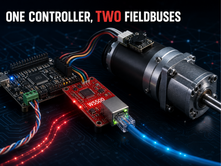
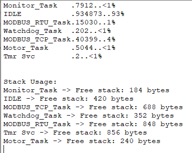
STM32F411 기반 DC 모터 컨트롤러에 Modbus RTU(RS485) 와 Modbus TCP(이더넷) 를 동시에 붙인 프로젝트입니다. 이더넷 구간은 W5500 이 TCP/IP를 통째로 처리하고, MCU는 Modbus 프레임 해석과 PID 제어에만 집중합니다. 두 통신 경로가 같은 홀딩 레지스터 배열 하나로 합류하는 설계 덕분에, 프로토콜이 둘이어도 제어 로직은 한 벌입니다. 측정된 CPU 부하는 약 7% 입니다.
개요
산업 설비 현장은 오랫동안 RS485 기반 Modbus RTU 로 돌아왔습니다. 새로 들어오는 설비는 이더넷을 기대하지만, 기존 라인을 한 번에 걷어낼 수는 없습니다. 두 세계가 한동안 공존하는 것이 현실입니다.
이 프로젝트는 그 공존 구간을 하나의 펌웨어로 해결합니다. 컨트롤러는 속도 모드(목표 RPM 유지)와 위치 모드(목표 각도 이동)를 지원하고, 어느 쪽 인터페이스로 접속하든 동일한 레지스터를 읽고 씁니다. 대상 독자는 STM32로 필드버스를 처음 다루는 임베디드 개발자, 그리고 기성 드라이브 대신 자체 컨트롤러가 필요한 소규모 설비 통합자입니다.
만든 사람은 MohammadKH 입니다. GitHub 이력을 보면 2023년 말부터 2024년까지는 자바스크립트·React 등 웹 프론트엔드 저장소가 이어지다가, 2025년 3월 Home_Automation_ESP32 로 임베디드에 들어섰고, 2026년 4월 이 STM32 프로젝트에 도달했습니다. 웹에서 IoT를 거쳐 산업 제어까지 2년이 걸린 셈입니다. 소스 파일 헤더를 보면 실제 개발은 2025년 12월부터 2026년 2월까지 진행됐고, 완성된 뒤 한 번에 공개됐습니다.
→ 프로젝트 저장소: https://github.com/MohammadR-Kh/Motor-Control-Modbus-RTU-Modbus-TCP
도입 배경 — 왜 이더넷이어야 하는가
Modbus TCP는 현대 설비의 표준 구현입니다. EtherCAT이나 PROFINET과 달리 전용 필드버스 하드웨어가 필요 없고, 일반 네트워크 카드와 라우터로 동작합니다. PLC뿐 아니라 일반 PC에서도 제어할 수 있다는 뜻입니다. 거의 모든 프로그래밍 언어가 TCP/IP 라이브러리를 제공하기 때문입니다.
다만 이 전환을 강제하는 법규나 규제는 확인하지 못했습니다. 업계 권고는 신규 설비에 이더넷 기반 프로토콜을 검토하라는 수준이며, 의무 조항은 아닙니다. 시장 흐름과 규제 근거를 구분해 두는 편이 정확합니다.
→ 참고: https://www.rtautomation.com/technologies/modbus/ → 참고: https://www.nanotec.com/us/en/knowledge-base-article/modbus-tcp-motors-controllers
산업 트렌드 — 오픈소스 하드웨어가 공장으로 들어가고 있습니다
이 프로젝트가 선 자리는 우연이 아닙니다. Arduino 는 릴레이 제조사 Finder와 함께 산업용 마이크로 PLC Opta 를 내놓았습니다. STM32H747 듀얼코어에 Modbus TCP와 Modbus RTU(RS485)를 모두 얹고 IEC-61131-3을 지원하는 제품으로, 이 프로젝트가 자작한 구성과 기능 목록이 거의 겹칩니다. Raspberry Pi 도 산업 등급 Compute Module 5를 출시했고, 전체 매출의 약 70~75%가 산업 고객에서 나옵니다. 플랫폼 제조사인 STMicroelectronics 역시 산업용 모터 제어 생태계를 확장하며 2026년 PCIM Europe에서 관련 솔루션을 전시했습니다.
주목할 점은 순서입니다. Opta가 먼저 상용화되고, 이 개인 프로젝트가 2026년에 같은 조합을 자작으로 재현했습니다. 이번 사례에서는 기업이 앞서고 커뮤니티가 뒤따랐습니다. 그만큼 이 구성이 이미 검증된 방향이라는 뜻이기도 합니다.
→ 참고: https://www.arduino.cc/pro/hardware-arduino-opta/ → 참고: https://www.developer-tech.com/news/raspberry-pi-launches-industrial-grade-compute-module-5/
아키텍처
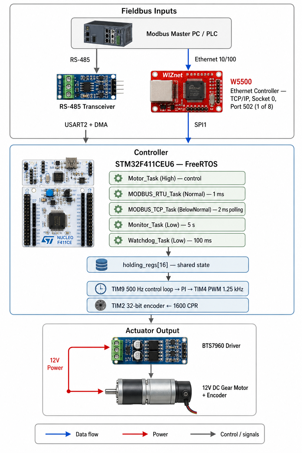
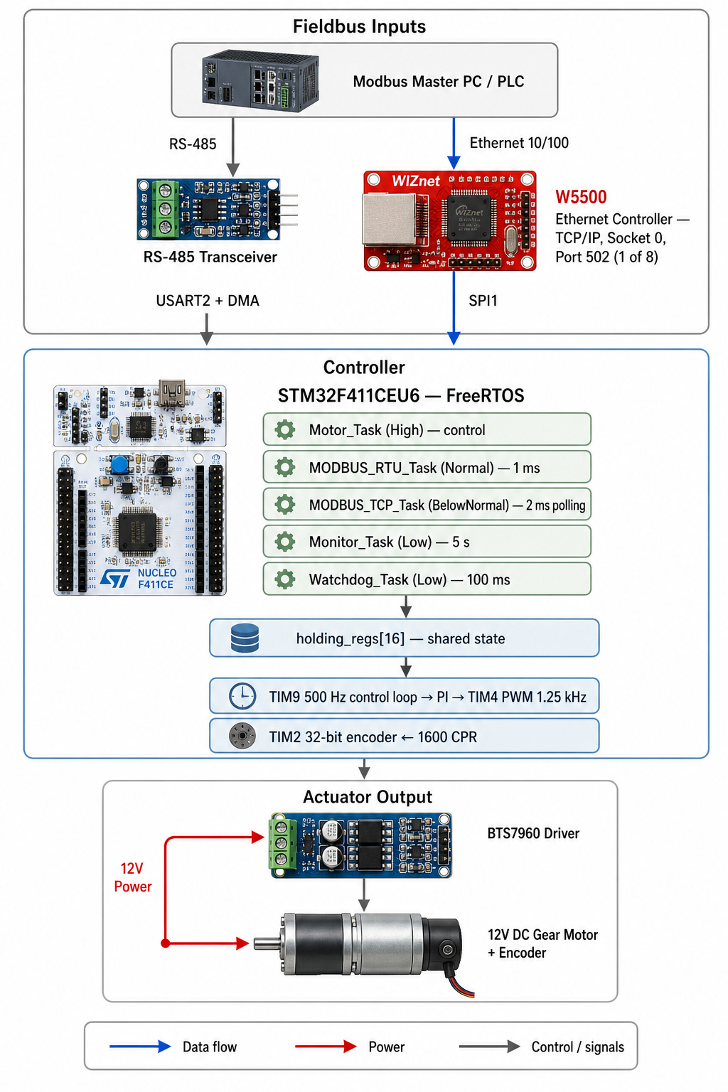
설계의 축은 두 통신 경로가 holding_regs[16] 배열 하나로 합류한다는 것입니다. 프로토콜 계층만 둘로 갈리고, 제어 계층은 단일합니다.
MCU 자원 배분
| 자원 | 용도 |
|---|---|
| SPI1 (PA8=CS, PB15=RST) | W5500 이더넷 |
| USART2 + DMA | Modbus RTU / RS485 |
| USART1 | 디버그 모니터 (DMA 미사용) |
| TIM2 (32bit) | 엔코더 CH1+CH2, 1600 CPR |
| TIM4 CH1/CH2 | PWM 1.25 kHz, PB0 = 드라이버 enable |
| TIM9 | 제어 루프 500 Hz |
| TIM10 | FreeRTOS RunTimeStats |
레지스터 맵
| 주소 | 이름 | 방향 |
|---|---|---|
| 0 | TARGET_RPM | 쓰기 |
| 1 | TARGET_POSITION (도) | 쓰기 |
| 2 | MODE (속도 / 위치) | 쓰기 |
| 3 | ACTUAL_RPM | 읽기 |
| 4 | ACTUAL_POSITION | 읽기 |
| 5 | PWM_OUTPUT | 읽기 |
기술 배경
Modbus RTU와 Modbus TCP의 프레임 구조
Modbus는 PDU(Protocol Data Unit) 라는 공통 알맹이를 갖고, 전송 매체에 따라 포장만 바꿉니다. PDU는 기능 코드 1바이트 + 데이터로 이루어집니다.
RTU 는 시리얼 회선 위를 달립니다. 회선에는 프레임 경계라는 개념이 없으므로, 앞에 슬레이브 주소 1바이트를 붙이고 뒤에 CRC16 2바이트를 붙입니다. 프레임을 끊는 것은 침묵입니다 — 표준은 3.5문자 시간 이상 전송이 없으면 회선을 유휴 상태로 선언하고, 그 뒤 처음 감지된 문자를 새 프레임의 시작으로 봅니다. 전송 오류를 스스로 잡아야 하기 때문에 CRC가 필수입니다.
→ 표준 문서: Modbus Organization, MODBUS over Serial Line Specification and Implementation Guide V1.02 → 참고: https://www.modbus.org/introduction-to-modbus
TCP 는 사정이 다릅니다. 앞에 MBAP 헤더 7바이트(트랜잭션 ID 2 + 프로토콜 ID 2 + 길이 2 + 유닛 ID 1)를 붙이고, CRC는 아예 없습니다. 이더넷 FCS와 TCP 체크섬이 이미 무결성을 보장하기 때문에 같은 일을 두 번 하지 않는 것입니다.
이 차이가 이 프로젝트의 구조를 설명합니다. 포장만 다르고 알맹이는 같으므로, 기능 코드 처리와 레지스터 접근 로직을 두 경로가 그대로 공유할 수 있습니다. 지원 기능은 양쪽 모두 F03(홀딩 레지스터 읽기), F06(단일 쓰기), F10(다중 쓰기) 입니다.
PI 폐루프와 위치 모드 프로파일
속도 모드는 목표 RPM과 실측 RPM의 오차를 좁혀 PWM 듀티를 조절합니다. 계수는 Kp 1.8, Ki 1.4, Kd 0.0 으로 선언돼 있지만, 출력 계산식에 미분항이 없습니다.
output = kp * error + ki * integral;즉 이름은 PID 구조체이되 실제로 도는 것은 PI 제어기입니다. kd 와 prev_error 필드는 확장 여지로 남아 있을 뿐 계산에 관여하지 않습니다. 기어모터처럼 기계 시정수가 큰 계에서는 PI만으로 정상 상태 오차를 없앨 수 있으므로 실용상 문제는 없습니다.
눈여겨볼 것은 적분 와인드업 방지입니다. 적분값을 출력 상한 / Ki 로 클램프해 두었습니다.
integral_limit = out_max / ki;이렇게 하면 적분항 단독으로는 출력 상한을 넘길 수 없습니다. 모터가 포화 상태로 오래 눌려 있어도 적분값이 무한정 쌓이지 않으므로, 목표가 바뀌었을 때 반대로 밀어내는 지연이 생기지 않습니다. 최종 출력도 ±MAX_DUTY(799) 로 다시 클램프합니다.
위치 모드는 별도의 비례 제어를 씁니다.
speed_cmd = KP_POSITION * error; // 0.035, ±3600 RPM 으로 포화오차에 비례해 목표 속도를 만들고 최대 RPM으로 잘라내는 구조입니다. 결과적으로 목표에서 멀면 최대 속도로 달리고 가까워질수록 속도가 저절로 줄어드는 감속 프로파일이 나옵니다. 오차가 10 counts 안에 들어오면 정지합니다. 위치 루프에는 적분항이 없습니다.
쿼드러처 엔코더 디코딩
엔코더는 90도 위상차를 둔 A·B 두 채널을 냅니다. 채널당 400펄스지만, 두 채널의 상승·하강 에지를 모두 세면 4체배가 되어 회전당 1600 counts 가 나옵니다. STM32의 타이머는 이 디코딩을 하드웨어로 처리하므로 CPU 개입이 없습니다. 여기서는 32비트 타이머인 TIM2를 써서 장시간 누적에도 카운터가 넘치지 않게 했습니다.
기술 특징
- 제어 루프를 태스크에서 분리 — TIM9가 500Hz로 엔코더 샘플링과 제어 갱신을 수행하고 태스크에는 알림만 보냅니다. 통신 부하가 늘어도 제어 주기가 흔들리지 않습니다.
- 우선순위가 설계 의도를 드러냅니다 — Motor(High) > RTU(Normal) > TCP(BelowNormal) > Monitor·Watchdog(Low). 제어가 최우선이고, 통신은 그 뒤입니다.
- RTU 경로에 DMA 적용 — USART2 송수신을
HAL_UART_Receive_DMA/HAL_UART_Transmit_DMA로 처리해 CPU 개입을 줄였습니다. - 적분 와인드업 방지 — 적분값을
출력 상한 / Ki로 클램프해 적분항 단독으로 출력 상한을 넘지 못하게 했습니다. 포화가 길어져도 목표 변경 시 반응이 늦지 않습니다. - 안전장치 — 독립 워치독(IWDG)이 펌웨어 정지 시 시스템을 리셋하고, FreeRTOS 스택 오버플로 검출이 켜져 있어 문제가 생긴 태스크를 UART로 보고합니다.
W5500이 맡는 구간
이 프로젝트에서 W5500은 SPI1에 물린 이더넷 종단 장치입니다. 칩 선택은 PA8, 리셋은 PB15이며, 리셋 시퀀스는 LOW 2ms 후 HIGH 2ms로 데이터시트가 요구하는 500µs 이상을 충분히 만족합니다. 네트워크 설정은 고정 IP 192.168.1.50/24, MAC은 00:08:DC:11:22:33 — 앞 세 바이트 00:08:DC 는 WIZnet의 등록 OUI 입니다.
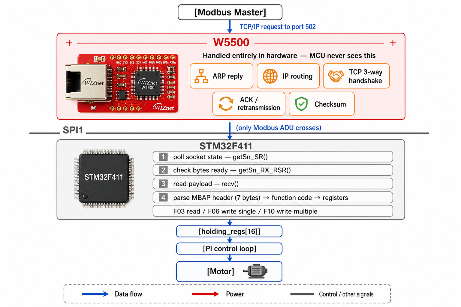
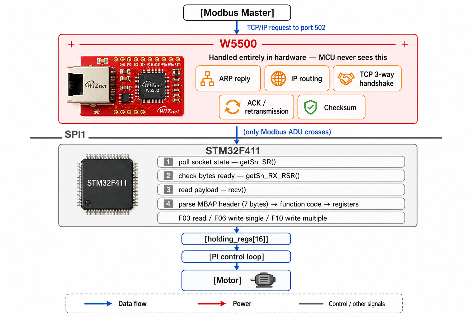
마스터가 포트 502 로 요청을 보내면 이렇게 흘러갑니다.
- W5500이 이더넷 프레임을 받습니다. ARP 응답, IP 라우팅, TCP 3-way 핸드셰이크, ACK, 재전송, 체크섬 계산까지 전부 칩 내부에서 끝납니다.
- MCU는 소켓 상태만 봅니다.
getSn_SR()로 상태를 읽어SOCK_CLOSED면 소켓을 열고,SOCK_INIT이면 리슨하고,SOCK_CLOSE_WAIT이면 연결을 끊습니다. 2ms 주기 폴링입니다. - 연결이 성립되면 데이터만 꺼냅니다.
getSn_RX_RSR()로 수신 바이트가 있는지 확인하고recv()를 호출하면, Modbus ADU만 MCU 버퍼로 넘어옵니다. - MCU가 하는 일은 여기부터입니다. MBAP 헤더 7바이트를 파싱하고, 기능 코드로 분기하고,
holding_regs[]를 읽거나 쓰고, 응답을 만들어send()로 넘깁니다. 범위를 벗어난 주소는 예외 코드 0x02로 돌려줍니다.
펌웨어에 TCP 스택 코드가 단 한 줄도 없습니다.
비유하자면 W5500은 국제 우편물 분류 창구입니다. 봉투에 붙은 주소, 통관, 재발송, 파손 확인은 창구가 전부 처리하고, MCU에게는 뜯어놓은 편지 본문만 건넵니다. MCU는 봉투를 본 적이 없습니다.
이 칩이 없었다면 STM32F411에는 이더넷 MAC 자체가 없으므로 외부 PHY와 소프트웨어 TCP/IP 스택을 얹어야 했을 것이고, 그만큼 플래시·RAM·CPU를 나눠 써야 했을 것입니다. 측정된 CPU 부하 7% 는 그 부담이 칩으로 넘어간 결과입니다.
WIZnet Makers의 유사 사례
같은 조합이 이미 여러 번 검증됐습니다.
Multi-Channel Industrial Weight Measurement with Modbus TCP — STM32F4 + FreeRTOS + W5500 + Modbus TCP로 MCU 계열, RTOS, 이더넷 컨트롤러가 모두 같습니다. 차이는 방향입니다. 이쪽은 다채널 중량 데이터를 올려보내는 계측이고, 본 프로젝트는 명령을 받아 움직이는 액추에이터입니다. → 프로젝트 링크: https://maker.wiznet.io/Benjamin/projects/stmf407vet6-cs5530-w5500-12/
STM32+W5500 for Modbus RTU and Modbus TCP conversion — RTU와 TCP 두 프로토콜을 하나의 STM32+W5500에서 다룬다는 점이 같습니다. 다만 이쪽은 프레임을 변환해 통과시키는 게이트웨이이고, 본 프로젝트는 두 프로토콜이 같은 레지스터 맵에 도달하는 종단 장치입니다. → 프로젝트 링크: https://maker.wiznet.io/chen/projects/stm32-w5500-for-modbus-rtu-and-modbus-tcp-conversion/
Implement MODBUS TCP Server with STM32 Cortex-M4 MCU — Cortex-M4에서 W5500을 TCP/IP 오프로드 엔진으로 삼아 포트 502 서버를 올린다는 골격이 동일합니다. 차이는 초점입니다. 이쪽은 서버 구현 자체가 주제이고, 본 프로젝트에서 서버는 제어 루프의 입출력 창구입니다. → 프로젝트 링크: https://maker.wiznet.io/bruno/projects/implement-modbus-tcp-server-with-stm32-cortex-m4-mcu/
세 사례 모두 STM32와 W5500으로 Modbus를 다루지만, 폐루프 제어와 결합한 것은 본 프로젝트뿐입니다. 통신이 단순 데이터 전달을 넘어 제어 목표값을 실시간으로 바꾸는 자리에 있다는 점이 차별점입니다.
| 항목 | 본 프로젝트 | Benjamin | chen | bruno |
|---|---|---|---|---|
| MCU | STM32F411 | STM32F407 | STM32 | Cortex-M4 |
| RTOS | FreeRTOS | FreeRTOS | 미상 | 미상 |
| 프로토콜 | RTU + TCP | TCP | RTU + TCP | TCP |
| 역할 | 제어 종단 | 계측 종단 | 게이트웨이 | 서버 구현 |
| 폐루프 제어 | 있음 | 없음 | 없음 | 없음 |
공통 설계 철학은 하나입니다. 네트워크는 칩에 맡기고 MCU는 자기 일을 한다. 본 프로젝트는 그 "자기 일"이 실시간 제어라는 점에서 부하 여유가 가장 절실했고, 실제로 그 여유를 확보했습니다.
테스트와 검증
이 프로젝트가 다른 자작 사례와 갈리는 지점은 주장을 파형으로 증명했다는 것입니다.
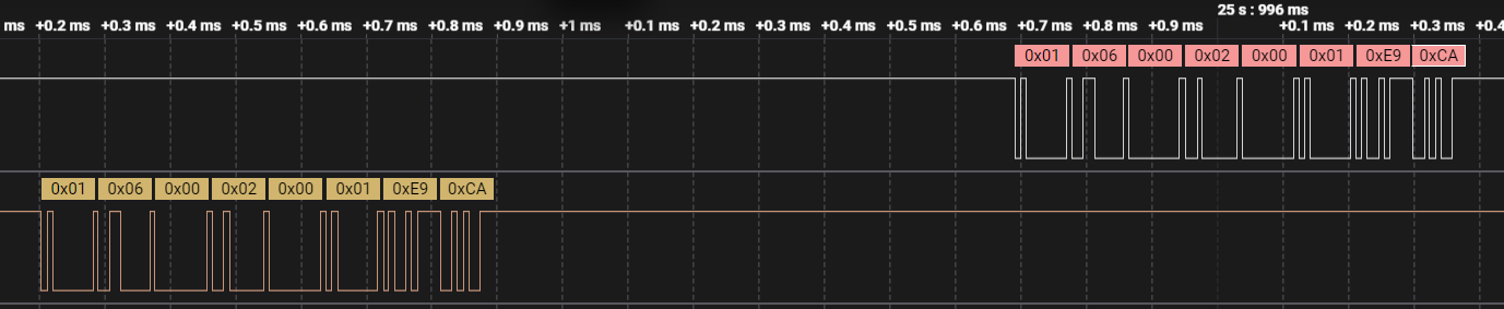
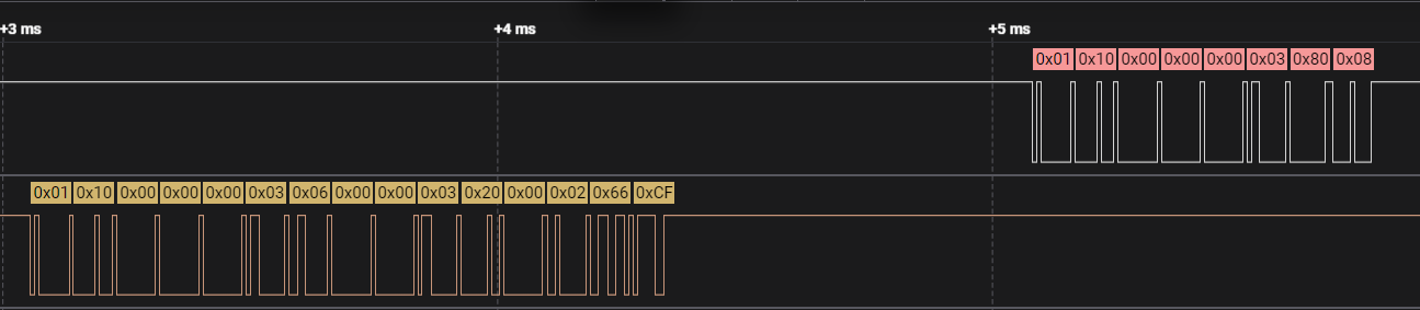
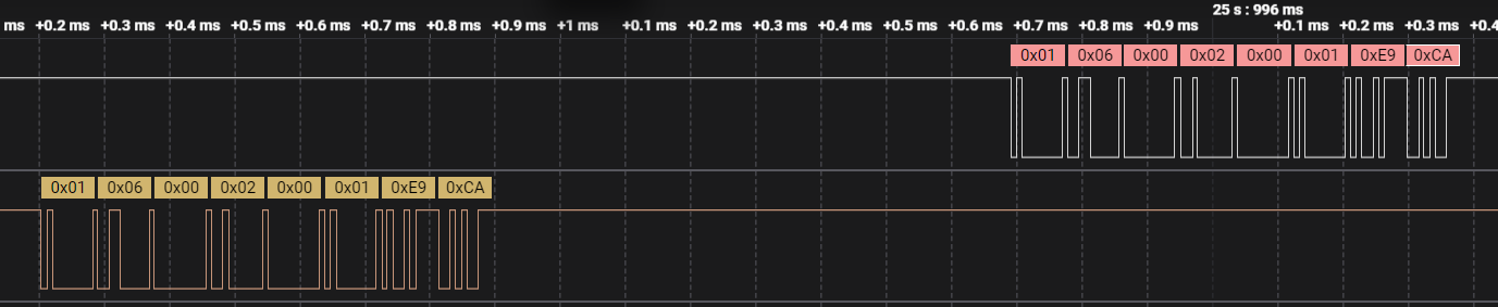
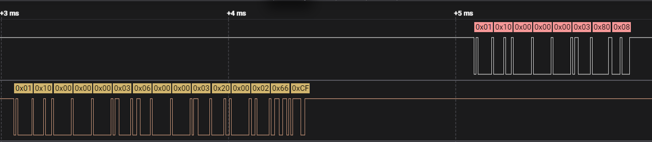
Modbus 프레임 검증 — 로직 애널라이저로 RS485 회선을 직접 잡아 F03·F06·F10 각각의 송신·수신 프레임을 캡처했습니다. 구현이 규격대로 동작하는지 눈으로 확인할 수 있습니다.
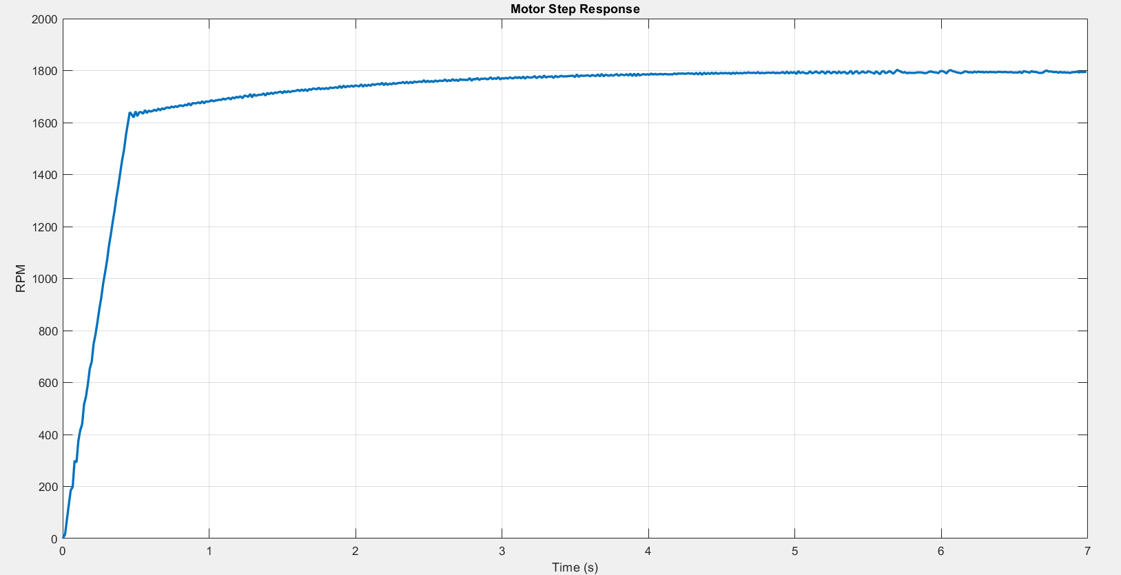
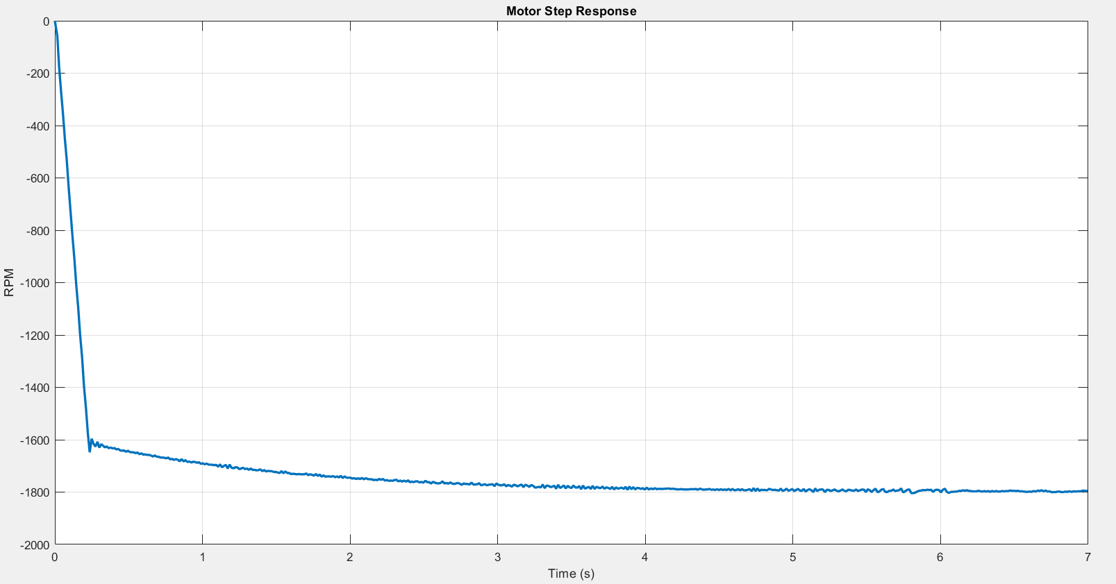
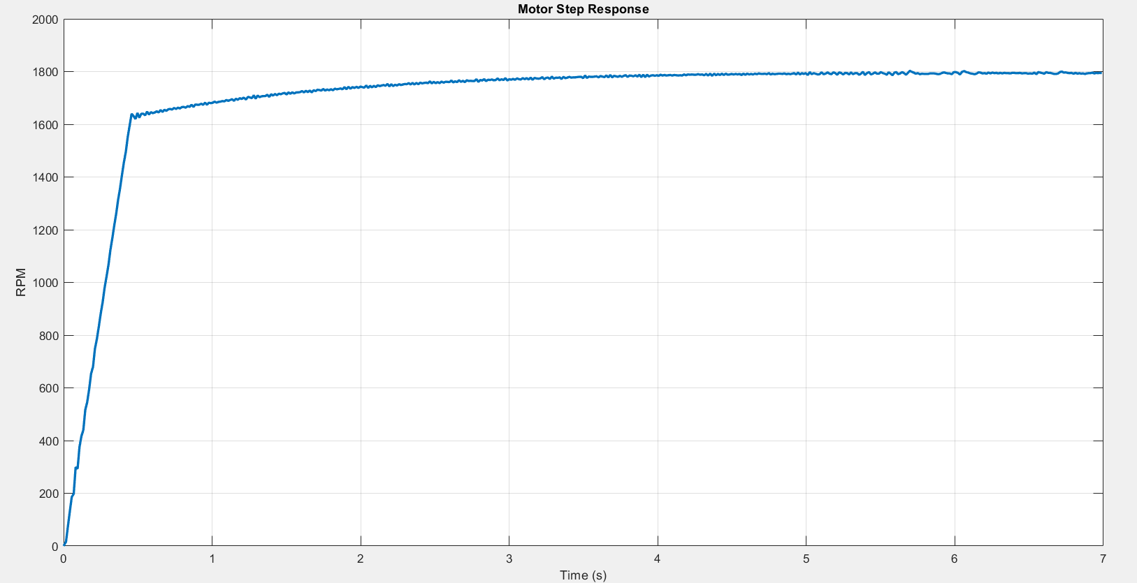
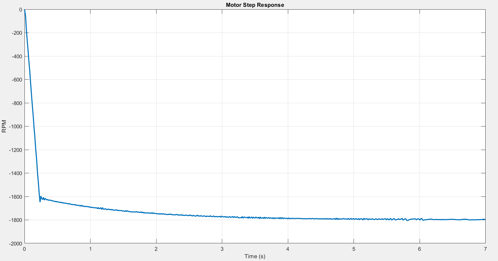
속도 스텝 응답 — 목표 RPM을 계단 형태로 바꾸며 시험했습니다. 낮은 오버슈트와 안정적인 정착을 보이며, 정회전과 역회전 양쪽에서 확인했습니다.
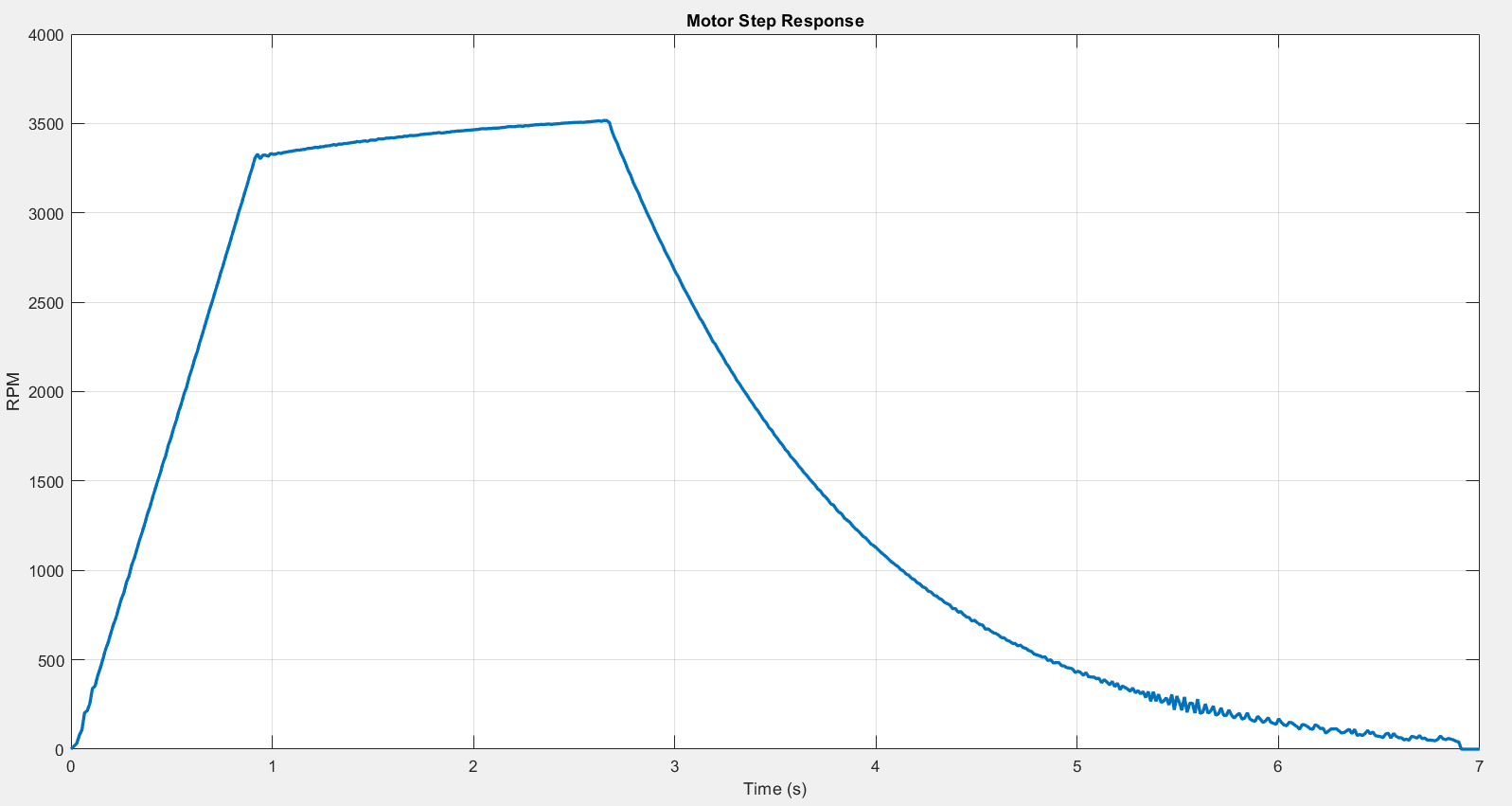
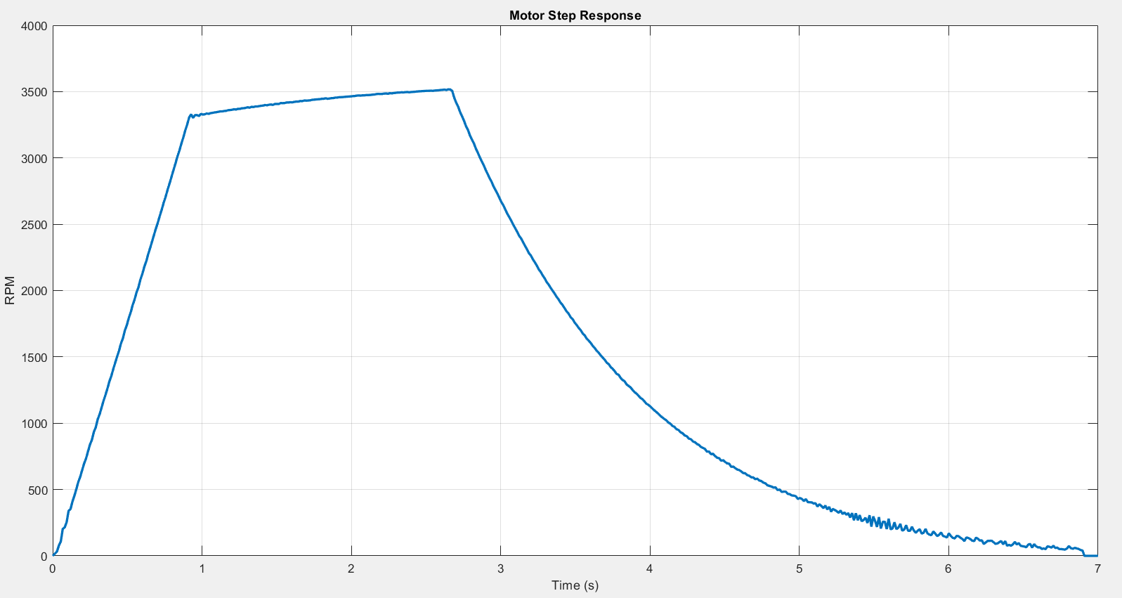
위치 모드 — 여러 목표 각도에 대해 허용 오차 안에서 부드럽게 정지하는 것을 확인했습니다. 목표에 가까워질수록 속도가 줄어드는 감속 구간이 그래프에 그대로 나타납니다.
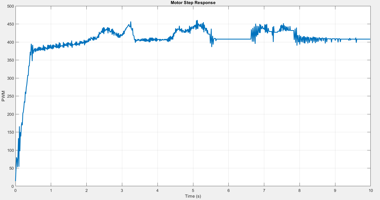
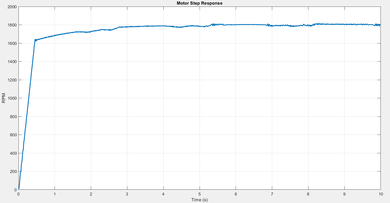
부하 외란 시험 — 모터 축에 기계적 부하를 걸어본 시험이 가장 인상적입니다. RPM은 유지되고 PWM 출력만 올라가며 보상하는 모습이 그대로 나타납니다. 폐루프가 실제로 닫혀 있다는 증거입니다.
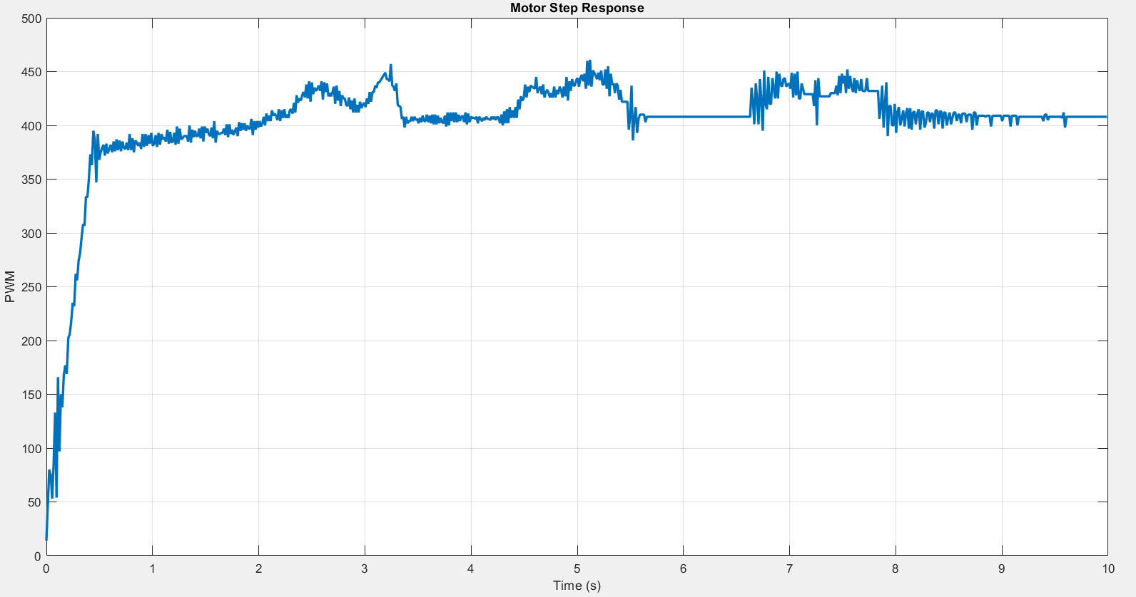
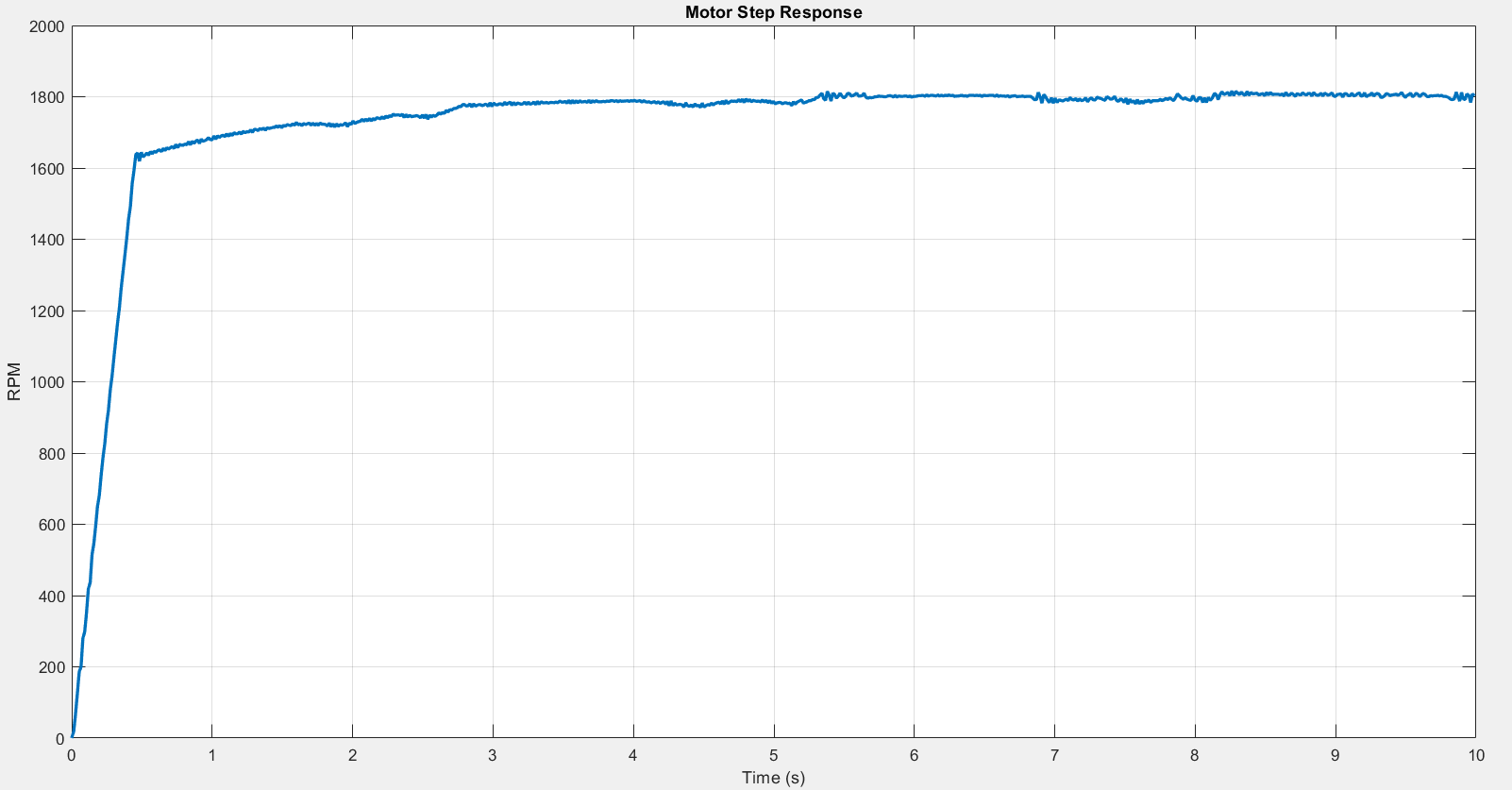
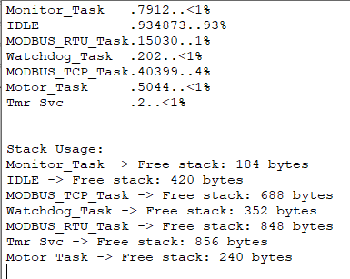
자원 사용량 — FreeRTOS RunTimeStats로 측정한 결과 CPU 약 7%, 유휴 약 93% 이며 모든 태스크 스택이 안전 범위에 있습니다. 이 수치는 500Hz 제어 루프, 1ms RTU 주기, 2ms TCP 폴링이 동시에 도는 상태에서 나온 값입니다.
비즈니스 가치
외부 관점 — 어디에 쓸 수 있는가
- 설비 전환기의 이중 투자 회피 — RS485 라인과 이더넷 라인이 공존하는 공장에서 컨트롤러를 두 벌 만들 필요가 없습니다. 재고와 펌웨어 관리 대상이 절반이 됩니다.
- 기존 SCADA에 무수정 편입 — 표준 Modbus 레지스터를 쓰므로 상위 시스템이 이 장치를 특별 취급하지 않아도 됩니다.
- 소형 다축 확장 — CPU 여유 93%는 같은 MCU에 축을 더 붙이거나 로깅·웹 UI를 얹을 수 있다는 뜻입니다. 오픈소스 하드웨어가 산업 시장으로 들어가는 흐름이 계속되는 한, 이런 소형 다목적 컨트롤러 수요는 일시적 유행이 아니라 구조적으로 늘어나는 쪽입니다.
내부 관점 — WIZnet에 주는 시사점
이 사례는 산업 프로토콜 계층에서 W5500의 위치를 명확히 보여줍니다. Modbus TCP는 애플리케이션 계층이고, 그 아래 전송 계층 전부를 칩이 가져갑니다. 응용이 무엇이든 이 경계는 바뀌지 않습니다.
더 중요한 것은 플랫폼 경쟁의 구도입니다. Arduino Opta가 STM32H747로 오고, Raspberry Pi가 CM5로 오고, ST가 자체 생태계를 넓힙니다. 어느 플랫폼이 산업 시장을 가져가든, MAC이 없는 MCU에 이더넷을 붙이는 문제는 그대로 남습니다. 곡괭이를 파는 자리가 여기입니다. 네트워크 계층은 결국 하드웨어 TCP/IP로 수렴합니다.
한계 및 개선 방향
훌륭한 구현이지만, 실제 산업 현장으로 옮길 때 다듬을 지점이 있습니다. 아래는 결함 지적이 아니라 다음 단계 제안입니다.
- TCP 스트림 재조립 — 현재
ModbusTCP_Process()는 길이가 12바이트 미만인 경우만 걸러내고, 한 번의recv()가 완전한 ADU 하나라고 전제합니다. TCP는 프레임 경계를 보장하지 않으므로 요청이 분할되거나 병합되면 어긋날 수 있습니다. MBAP 헤더의 길이 필드를 기준으로 재조립하는 것이 정공법입니다. - 동시 접속 확장 — 지금은 소켓 0 하나만 사용해 마스터 한 대만 붙을 수 있습니다. W5500은 독립 하드웨어 소켓 8개와 32KB 내부 버퍼를 제공하므로, 소켓별로 세션 상태를 나눠 관리하면 SCADA와 엔지니어링 툴이 동시에 접속할 수 있습니다. → 제품 사양: https://wiznet.io/products/ethernet-chips/w5500
- SPI 버스트 전송 — 현재 등록된 콜백은
reg_wizchip_cs_cbfunc와reg_wizchip_spi_cbfunc둘뿐이고, 후자는 1바이트씩 블로킹 전송합니다. WIZnet ioLibrary가 제공하는 버스트 콜백(reg_wizchip_spiburst_cbfunc)을 추가로 등록하고 DMA를 붙이면 프레임당 호출 오버헤드가 크게 줄어듭니다. RTU 경로는 이미 DMA를 쓰고 있으므로 같은 방식을 TCP 경로에도 적용하면 구조가 대칭이 됩니다. - 인터럽트 기반 수신 — 2ms 폴링 대신 W5500의 INTn 핀을 쓰면 응답 지연의 상한을 낮출 수 있습니다.
- 네트워크 유연성 — 저장소에 DHCP 드라이버가 이미 포함돼 있으나 현재는 고정 IP만 사용합니다. 게이트웨이도
0.0.0.0이라 같은 서브넷 안에서만 통신합니다. DHCP를 활성화하면 현장 배치가 쉬워집니다.
FAQ
Q. 따라 만들려면 난이도가 어느 정도입니까? STM32CubeIDE로 FreeRTOS 프로젝트를 만들어본 경험이 있다면 접근할 만합니다. 가장 손이 많이 가는 부분은 펌웨어가 아니라 엔코더 배선과 PID 계수 조정입니다. W5500 쪽은 WIZnet ioLibrary를 그대로 쓰므로 SPI 콜백 네 개와 CS·RST 핀만 연결하면 됩니다.
Q. RTU와 TCP로 동시에 접속하면 어떻게 됩니까? 두 태스크가 같은 holding_regs[] 를 만지므로 마지막에 쓴 값이 이깁니다. 소스를 확인해 보면 이 배열에 뮤텍스나 임계 구역이 걸려 있지 않습니다. 16비트 단일 레지스터 접근은 원자적이라 값이 깨지지는 않지만, F10으로 여러 레지스터를 한 번에 쓰는 도중 다른 경로가 끼어들면 값의 조합이 어긋날 수 있습니다. 실제 운용에서는 쓰기 권한을 한쪽 인터페이스로 제한하거나 뮤텍스로 묶는 편이 안전합니다.
Q. 마스터를 여러 대 붙이려면 무엇을 바꿔야 합니까? 소켓 배열을 만들고 각 소켓의 상태 머신을 개별로 돌리면 됩니다. W5500이 소켓 8개와 32KB 내부 버퍼를 제공하므로 하드웨어 교체 없이 확장 가능합니다.
Q. MCU를 고를 때 이더넷 MAC 내장 품목을 쓰면 되지 않습니까? 가능하지만 계산이 달라집니다. MAC 내장 MCU도 외부 PHY와 소프트웨어 TCP/IP 스택이 필요하고, 그만큼 플래시·RAM·CPU를 씁니다. 이 프로젝트처럼 제어 루프에 여유를 남겨야 하는 경우에는 하드웨어 TCP/IP 쪽이 유리합니다. 저가 MCU를 그대로 쓸 수 있다는 점도 BOM에서 무시할 수 없습니다.
Summary
This project pairs an STM32F411-based DC motor controller with Modbus RTU (RS-485) and Modbus TCP (Ethernet) at the same time. On the Ethernet side, the W5500 handles the entire TCP/IP stack, so the MCU only parses Modbus frames and runs the control loop. Because both communication paths converge on a single holding-register array, two protocols still need only one set of control logic. Measured CPU load is about 7%.
Overview
Industrial plants have run on RS-485 Modbus RTU for decades. New equipment expects Ethernet, but nobody rips out an existing line overnight. The two worlds coexist for a long time.
This project solves that overlap with one firmware image. The controller supports a speed mode (hold a target RPM) and a position mode (move to a target angle), and it exposes the same registers no matter which interface you connect through. It targets embedded developers meeting fieldbus for the first time on STM32, and small system integrators who need their own controller instead of an off-the-shelf drive.
The author is MohammadKH. Their GitHub history shows web frontend repositories in JavaScript and React through late 2023 and 2024, then a move into embedded work with Home_Automation_ESP32 in March 2025, and finally this STM32 project in April 2026 — web to IoT to industrial control in roughly two years. Source file headers show the actual development ran from December 2025 to February 2026; the finished project was published in one push.
→ Project repository: https://github.com/MohammadR-Kh/Motor-Control-Modbus-RTU-Modbus-TCP
Why Ethernet — the Case for the Move
Modbus TCP is the common implementation for modern installations. Unlike EtherCAT or PROFINET, it requires no fieldbus-specific hardware and runs on ordinary network cards and routers. That means a plain PC can drive it as easily as a PLC, because nearly every programming language ships a TCP/IP library.
That said, we found no law or regulation that mandates this migration. Industry guidance recommends considering Ethernet-based protocols for new installations, but it stops short of a requirement. It is more accurate to keep market direction and regulatory grounding separate.
→ Reference: https://www.rtautomation.com/technologies/modbus/ → Reference: https://www.nanotec.com/us/en/knowledge-base-article/modbus-tcp-motors-controllers
Industry Trend — Open-Source Hardware Is Moving onto the Factory Floor
This project did not land where it did by accident. Arduino partnered with relay manufacturer Finder to release Opta, an industrial micro-PLC. It carries an STM32H747 dual-core MCU, both Modbus TCP and Modbus RTU (RS-485), and IEC-61131-3 support — almost the same feature list this project built by hand. Raspberry Pi shipped an industrial-grade Compute Module 5, and roughly 70–75% of its revenue now comes from industrial customers. STMicroelectronics, the platform vendor here, is expanding its own industrial motor control ecosystem and showed related solutions at PCIM Europe 2026.
The ordering is worth noting. Opta reached the market first, and this personal project reproduced the same combination by hand in 2026. In this case, the companies moved first and the community followed — which is itself evidence that the architecture is a proven direction.
→ Reference: https://www.arduino.cc/pro/hardware-arduino-opta/ → Reference: https://www.developer-tech.com/news/raspberry-pi-launches-industrial-grade-compute-module-5/
Architecture
The organizing idea is that both communication paths converge on one holding_regs[16] array. Only the protocol layer splits in two; the control layer stays single.
MCU Resource Allocation
| Resource | Purpose |
|---|---|
| SPI1 (PA8 = CS, PB15 = RST) | W5500 Ethernet |
| USART2 + DMA | Modbus RTU / RS-485 |
| USART1 | Debug monitor (no DMA) |
| TIM2 (32-bit) | Encoder CH1 + CH2, 1600 CPR |
| TIM4 CH1/CH2 | PWM 1.25 kHz, PB0 = driver enable |
| TIM9 | Control loop 500 Hz |
| TIM10 | FreeRTOS RunTimeStats |
Register Map
| Address | Name | Direction |
|---|---|---|
| 0 | TARGET_RPM | Write |
| 1 | TARGET_POSITION (degrees) | Write |
| 2 | MODE (speed / position) | Write |
| 3 | ACTUAL_RPM | Read |
| 4 | ACTUAL_POSITION | Read |
| 5 | PWM_OUTPUT | Read |
Technology Background
Frame Structure: Modbus RTU vs Modbus TCP
Modbus keeps a common core called the PDU (Protocol Data Unit) and changes only the wrapper depending on the transport. A PDU is one function-code byte plus data.
RTU runs over a serial line. A serial line has no concept of frame boundaries, so RTU prepends a one-byte slave address and appends a two-byte CRC16. Silence marks the boundary: the standard declares the link idle after at least 3.5 character times with no transmission, and treats the next character detected as the start of a new frame. CRC is mandatory because the frame has to catch its own transmission errors.
→ Standard: Modbus Organization, MODBUS over Serial Line Specification and Implementation Guide V1.02 → Reference: https://www.modbus.org/introduction-to-modbus
TCP is a different situation. It prepends a 7-byte MBAP header (transaction ID 2 + protocol ID 2 + length 2 + unit ID 1) and carries no CRC at all. The Ethernet FCS and the TCP checksum already guarantee integrity, so the frame does not repeat that work.
This difference explains the project's structure. Since only the wrapper differs while the core stays the same, both paths reuse the identical function-code handling and register access logic. Both interfaces support F03 (read holding registers), F06 (write single), and F10 (write multiple).
The PI Loop and the Position Profile
Speed mode narrows the error between target RPM and measured RPM to adjust the PWM duty. The gains are declared as Kp 1.8, Ki 1.4, Kd 0.0, but the output equation contains no derivative term:
output = kp * error + ki * integral;So the struct is named PID, yet what actually runs is a PI controller. The kd and prev_error fields sit there as room to grow and take no part in the calculation. For a gear motor with a large mechanical time constant, PI alone removes steady-state error, so this costs nothing in practice.
The detail worth noticing is integral anti-windup. The integral term is clamped to output limit / Ki:
integral_limit = out_max / ki;With that bound, the integral term alone can never exceed the output limit. Even when the motor sits saturated for a long stretch, the accumulator stops growing, so a change of target does not have to unwind a backlog first. The final output is clamped again to ±MAX_DUTY (799).
Position mode uses a separate proportional controller:
speed_cmd = KP_POSITION * error; // 0.035, saturated at ±3600 RPMIt turns error into a target speed and clips it at the maximum RPM. The result is a natural deceleration profile: full speed while far from the target, and speed that falls off on its own as the target approaches. Motion stops once the error is within 10 counts. The position loop has no integral term.
Quadrature Encoder Decoding
The encoder produces channels A and B, 90 degrees apart. Each channel gives 400 pulses, but counting every rising and falling edge on both channels multiplies by four, yielding 1600 counts per revolution. The STM32 timer decodes this in hardware, so the CPU is not involved. The design uses TIM2, a 32-bit timer, so the counter does not overflow during long runs.
Technical Highlights
- The control loop is decoupled from the tasks — TIM9 samples the encoder and updates control at 500 Hz, then merely notifies the task. Control timing does not drift as communication load rises.
- Priorities reveal the design intent — Motor (High) > RTU (Normal) > TCP (BelowNormal) > Monitor and Watchdog (Low). Control comes first; communication comes after.
- DMA on the RTU path — USART2 transfers use
HAL_UART_Receive_DMAandHAL_UART_Transmit_DMAto cut CPU involvement. - Integral anti-windup — the integral is clamped to
output limit / Kiso it alone cannot push past the output ceiling. Long saturation does not delay the response to a new target. - Safety mechanisms — an independent watchdog (IWDG) resets the system if the firmware stalls, and FreeRTOS stack overflow detection is enabled to report the offending task over UART.
Where W5500 Fits
In this project the W5500 is the Ethernet endpoint on SPI1. Chip select is PA8 and reset is PB15; the reset sequence holds LOW for 2 ms then HIGH for 2 ms, comfortably above the 500 µs the datasheet requires. The network is configured statically at 192.168.1.50/24, with MAC 00:08:DC:11:22:33 — the first three bytes, 00:08:DC, are WIZnet's registered OUI.
When a master sends a request to port 502, here is what happens.
- The W5500 receives the Ethernet frame. ARP replies, IP routing, the TCP three-way handshake, ACKs, retransmission, and checksum calculation all finish inside the chip.
- The MCU only watches socket state. It reads status through
getSn_SR(): open a socket onSOCK_CLOSED, listen onSOCK_INIT, disconnect onSOCK_CLOSE_WAIT. It polls every 2 ms. - Once the connection is up, it pulls out data only.
getSn_RX_RSR()reports whether bytes are waiting, and a call torecv()delivers just the Modbus ADU into the MCU buffer. - The MCU's job starts here. It parses the 7-byte MBAP header, branches on the function code, reads or writes
holding_regs[], builds a response, and hands it back throughsend(). Out-of-range addresses return exception code 0x02.
There is not a single line of TCP stack code in the firmware.
Think of the W5500 as an international mail sorting desk. Addressing, customs, redelivery, and damage checks are all handled at the desk, and the MCU receives only the opened letter. It never sees the envelope.
Without this chip, the STM32F411 — which has no Ethernet MAC of its own — would need an external PHY and a software TCP/IP stack, spending flash, RAM, and CPU on all three. The measured 7% CPU load is what it looks like when that burden moves into the chip instead.
Similar Projects on WIZnet Makers
The same combination has been validated several times already.
Multi-Channel Industrial Weight Measurement with Modbus TCP — STM32F4 plus FreeRTOS plus W5500 plus Modbus TCP, matching the MCU family, the RTOS, and the Ethernet controller. The difference is direction: that project is measurement pushing data upward, while this one is an actuator taking commands. → Project link: https://maker.wiznet.io/Benjamin/projects/stmf407vet6-cs5530-w5500-12/
STM32+W5500 for Modbus RTU and Modbus TCP conversion — it also handles both protocols on a single STM32 and W5500. But that project is a gateway that converts and passes frames through, whereas this one is an endpoint where both protocols reach the same register map. → Project link: https://maker.wiznet.io/chen/projects/stm32-w5500-for-modbus-rtu-and-modbus-tcp-conversion/
Implement MODBUS TCP Server with STM32 Cortex-M4 MCU — the skeleton is identical: a Cortex-M4 running a port 502 server with the W5500 as a TCP/IP offload engine. The difference is focus. There, the server implementation is the subject; here, the server is the I/O window of a control loop. → Project link: https://maker.wiznet.io/bruno/projects/implement-modbus-tcp-server-with-stm32-cortex-m4-mcu/
All three handle Modbus on STM32 and W5500, but only this project couples it to a closed control loop. Communication here does more than move data — it changes a control setpoint in real time.
| Item | This project | Benjamin | chen | bruno |
|---|---|---|---|---|
| MCU | STM32F411 | STM32F407 | STM32 | Cortex-M4 |
| RTOS | FreeRTOS | FreeRTOS | Unknown | Unknown |
| Protocols | RTU + TCP | TCP | RTU + TCP | TCP |
| Role | Control endpoint | Measurement endpoint | Gateway | Server implementation |
| Closed-loop control | Yes | No | No | No |
One design philosophy runs through all of them: hand the network to the chip and let the MCU do its own job. This project needed that headroom most, because its own job is real-time control — and it demonstrably got the headroom.
Testing and Verification
What separates this project from most hobby builds is that it proves its claims with captured waveforms.
Modbus frame verification — a logic analyzer was placed directly on the RS-485 line to capture the transmit and receive frames for F03, F06, and F10. You can confirm by eye that the implementation matches the specification.
Speed step response — the target RPM was stepped up and down. The response shows low overshoot and stable settling, confirmed in both directions of rotation.
Position mode — several target angles were tested, each stopping smoothly within tolerance. The deceleration band as the target approaches is visible directly in the plot.
Load disturbance test — the most convincing run applies a mechanical load to the motor shaft. The RPM holds while the PWM output rises to compensate, exactly as shown in the trace. That is evidence the loop is genuinely closed.
Resource usage — FreeRTOS RunTimeStats reports about 7% CPU and 93% idle, with every task stack inside a safe margin. These numbers come from a state where the 500 Hz control loop, the 1 ms RTU cycle, and the 2 ms TCP polling all run at once.
Business Value
External View — Where This Applies
- No double investment during a migration — a plant where RS-485 and Ethernet lines coexist does not need two controller variants. Inventory and firmware maintenance both halve.
- Drops into existing SCADA unchanged — because it uses standard Modbus registers, the supervisory system does not have to treat this device as a special case.
- Compact multi-axis expansion — 93% CPU headroom means the same MCU can take another axis, or add logging and a web UI. As long as open-source hardware keeps moving into industrial markets, demand for small general-purpose controllers like this grows structurally rather than as a passing trend.
Internal View — What This Means for WIZnet
This case shows where the W5500 sits in the industrial protocol stack. Modbus TCP is the application layer, and the chip takes the entire transport layer beneath it. That boundary does not shift with the application.
More importantly, consider the platform competition. Arduino Opta arrives on the STM32H747, Raspberry Pi arrives with CM5, and ST widens its own ecosystem. Whichever platform wins the industrial market, the problem of adding Ethernet to an MCU without a MAC remains. That is where the picks and shovels are sold. The network layer converges on hardwired TCP/IP either way.
Limitations and Future Improvements
This is a solid implementation, but a few points would need attention before a real plant deployment. The list below is a set of next steps, not a fault report.
- TCP stream reassembly —
ModbusTCP_Process()currently rejects only lengths below 12 bytes and assumes onerecv()call equals one complete ADU. TCP does not preserve frame boundaries, so a split or merged request can go wrong. The correct approach is to reassemble using the length field in the MBAP header. - Concurrent connections — only socket 0 is in use, so a single master can connect. The W5500 provides 8 independent hardware sockets and a 32 KB internal buffer, so tracking session state per socket would let SCADA and an engineering tool connect at the same time. → Product specification: https://wiznet.io/products/ethernet-chips/w5500
- SPI burst transfers — only
reg_wizchip_cs_cbfuncandreg_wizchip_spi_cbfuncare registered today, and the latter transfers one byte at a time, blocking. Registering the burst callback (reg_wizchip_spiburst_cbfunc) that WIZnet ioLibrary provides and attaching DMA would cut per-frame call overhead substantially. The RTU path already uses DMA, so applying the same approach to the TCP path makes the structure symmetric. - Interrupt-driven reception — using the W5500's INTn pin instead of 2 ms polling would lower the upper bound on response latency.
- Network flexibility — the repository already includes a DHCP driver, but the build uses a static IP only. The gateway is
0.0.0.0, so communication stays within the same subnet. Enabling DHCP would simplify field deployment.
FAQ
Q. How hard is this to reproduce? If you have built a FreeRTOS project in STM32CubeIDE before, it is within reach. The most demanding part is not the firmware but the encoder wiring and PID tuning. The W5500 side uses WIZnet ioLibrary as-is, so you only wire four SPI callbacks plus the CS and RST pins.
Q. What happens if RTU and TCP connect at the same time? Both tasks touch the same holding_regs[], so the last write wins. Checking the source shows no mutex or critical section guards that array. A single 16-bit register access is atomic, so no value is torn — but if another path interrupts an F10 write spanning several registers, the combination of values can end up inconsistent. In production, restrict write access to one interface or protect the array with a mutex.
Q. What would it take to attach multiple masters? Build a socket array and run each socket's state machine independently. Since the W5500 offers 8 sockets and a 32 KB internal buffer, this scales without any hardware change.
Q. Why not just pick an MCU with a built-in Ethernet MAC? You can, but the arithmetic changes. An MCU with a MAC still needs an external PHY and a software TCP/IP stack, and those consume flash, RAM, and CPU. When you have to leave headroom for a control loop, as this project does, hardwired TCP/IP comes out ahead. Being able to keep a low-cost MCU is not a small line item in the BOM either.