Embedded 101: Chip Pins vs Dev Board Pins — What’s the Difference?
Stop frying your Pico! Learn to read the pinout diagram: power, GPIO, ADC, and debug pins explained for safe, correct wiring every time.
COMPONENTS
PROJECT DESCRIPTION
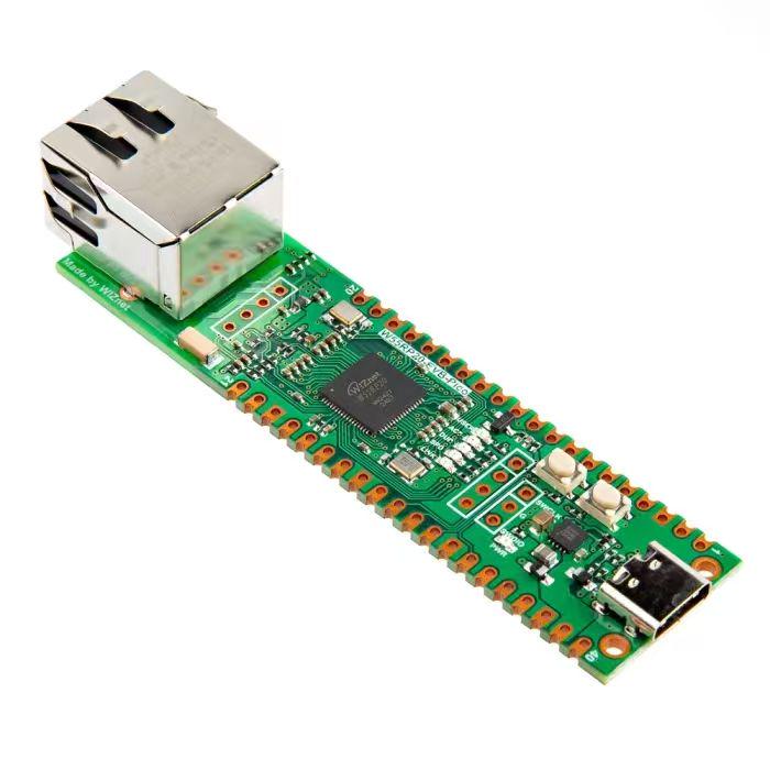
【Preliminary Note】The original hardware example in this article was written based on the RP2040. The actual hardware used in this hands-on demonstration features the W55RP20 as the main controller chip. The circuit logic and UF2 flashing operation principles are universally applicable, with only the main controller model differing. The original chip model mentioned in the circuit descriptions below is provided for reference purposes only.
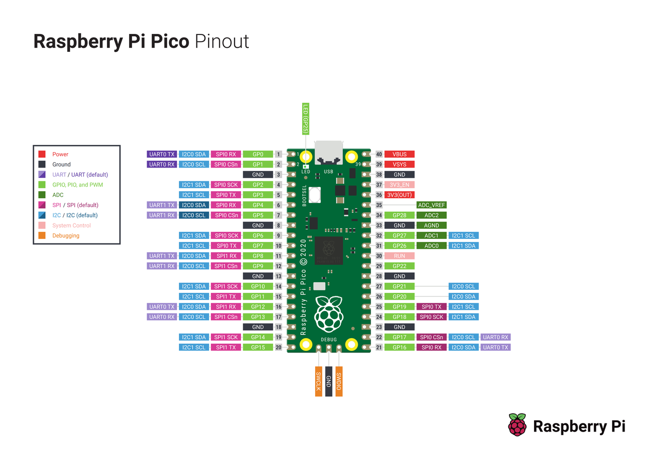
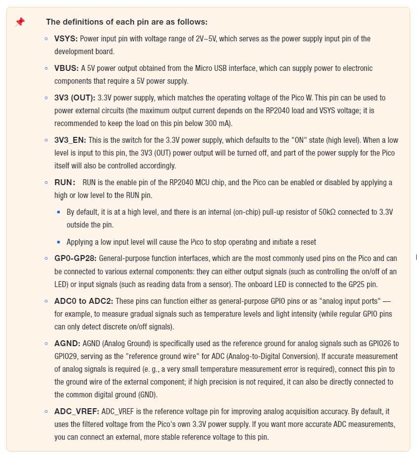
The pinout diagram serves as the "external interface manual" for the Raspberry Pi Pico — when you want to connect external components like LEDs or sensors to the Pico, random pin connections may either result in wrong power supply hookup that burns out the hardware, or use pins that do not support the functions required by the component (for example, selecting a purely digital pin when the sensor requires an analog signal); referring to the pinout clarifies the function of each pin (whether it is a power pin, ground pin, or signal pin) and the supported functions, which not only prevents equipment damage from incorrect connections but also accurately fulfills requirements such as "lighting up the LED and enabling the sensor to transmit data".
Figure 1.3 Pinout Diagram of Raspberry Pi Pico Development Board
You can first refer to the "legend" in the upper left corner (colors correspond to pin types: for example, red stands for power supply and green for GPIO), then locate the pin numbers on the board (such as GP0 and GP25); the text next to each number (such as UART-TX and ADC0) indicates the pin's additional functions. Finally, based on the requirements of the component you need to connect (for instance, find the red 3V3 pin if 3.3V power supply is needed, or find the pin marked with ADC if analog signal input is required), you can identify the appropriate pin by matching the colors in the legend with the function labels beside the pins.